


Marissa Farrell
-
Posts
1,474 -
Joined
-
Last visited
Content Type
Profiles
Forums
Events
Articles
Marionette
Store
Everything posted by Marissa Farrell
-
My best guess is that your 'None' class has its fill attribute set to None and that your columns are being created with those attributes. In the OIP, when you click the 'Get Finishes/Classes', what are the classes listed? If they are set to either 'None' or <Column Class>, in your navigation palette, under the Classes tab, right click on the 'None' class and select 'Edit', what does that window look like? That is how I was able to reproduce what you were seeing.
-
This is being internally tracked and worked on. VB-138950
-

Marionette for beginners
Marissa Farrell replied to MRD Mark Ridgewell's topic in General Discussion
Currently, the only thing in existence that I am aware of is this: http://developer.vectorworks.net/index.php/Marionette_Node_Reference However, I believe the last time it was touched was right after Marionette's initial release in Vectorworks 2016, so the list may be outdated in some places. Since then we've added a few new nodes and removed some nodes that were considered obsolete, but it can be a decent starting place for you. I'm also always available to help you out, so if you're ever stuck, just let me know! -
Pat, Can I ask what you think is difficult about working with existing objects? The only limitation I can think of is that you cannot run your network on things physically selected, I believe almost every other method (if not all other methods) of getting the handles to objects is available within Marionette. In this case, since the objects would be selected based on criteria rather than if they are selected or not, Marionette is an acceptable tool for this. Not that I disagree that those who can script should just write their own, even I prefer scripting over Marionette in some cases.
-
I would use the 'Mix2' node with the List Matching set to 'Cross Reference' CompareLists_MFarrell.vwx
-
Script which adds automatically values along a path
Marissa Farrell replied to rebu1985's topic in Vectorscript
But would it be worth it? -
Version 2.0.2023
332 downloads
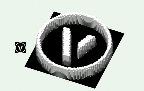
This network will read the data in an image existing in your file, for example, the color of each of the pixels, and create rectangles/extrusions with the same fill color. The extrusions are created at a height correlating to their brightness. The data extracted from the image could be used in many additional ways. Please look at the different version options to locate a file for the Vectorworks version you are running. -
.thumb.JPG.cb6f85903ac487ee2dd3f9ba1e2f0366.JPG)
Version 1.0.0
82 downloads
This circle object will center text on it. Easily modifiable to use your own custom text, currently will place the coordinates of its center. -
Version 1.0.0
61 downloads
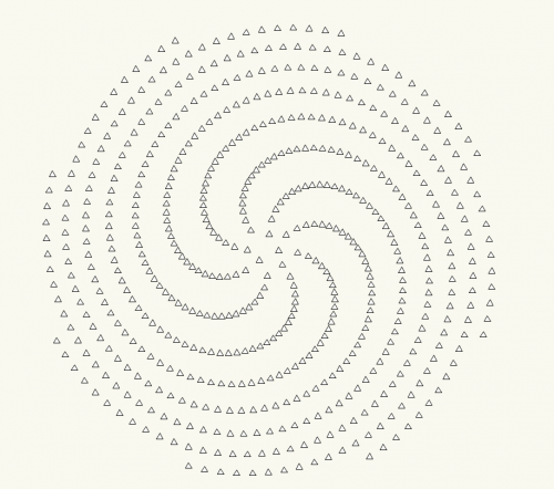
The golden angle node will give you the location of points following the 'Golden Spiral' which presents itself everywhere in nature. -
Layer Scale for New Design Layers?
Marissa Farrell replied to Andy Broomell's question in Known Issues
Alan is right, I tracked this all down last year. It will always create a design layer based on the scale of the last one you created, regardless if it's in the same document or a new document, or even if you are switching between multiple documents. There have been various discussions on other possibilities, but there has been no agreement on a different solution, so I don't see that changing any time soon. VB-111353 -
I don't think the preferences change during that process, though, I think they are just ignored. When I insert a beam, those values still persist in both the OIP and the preferences window. I don't think that's it. EDIT: the beams, etc. CAN still use those bounds for their beginning and end points.
-
All I did was change the start and end bounds popups to 'layer elevation' and made sure that the end offset did not match the start offset. When I opened your file, the popup fields were blank, which is probably what was causing the issue, however I can't get anything myself to end up like that. I have noooo idea how you drew your zero length member. I so far have consistently been thwarted by the alert when I try. There's probably something here, we just need to track down how to get me to consistently reproduce it
-
Could anyone with this problem please do the following for me - In a new, blank document, activate the structural member tool and go to its preferences In the 'Geometry' pane, what do the defaults for 'Elevation' say? After that, please try to reproduce your issue, and then again tell me what you see in 'Elevation' I really, reaaaalllyyyyy want to track this down.
-
Kevin, With your file, I am also getting the alert, however you can get it out of that state by changing your elevation values in the preferences in the Geometry pane, so it's not REALLY unusable and probably still WAD because of the ability to modify your preferences back into a usable state. I'm not sure that we would want to force different height references on a user, the error message will inform the user that they are trying to place something of zero height which would prompt them to check those values. I can also say that it will go into that state if you try to insert it onto a sheet layer with referenced elevations because sheet layers have no 3D references. I however still cannot get it into that state on my own. There appears to have been an issue reported and resolved about users not being alerted when they attempted to create a zero length/height member, the error alert is new is SP3, but it wasn't due to any circumstances that you guys have mentioned about just getting that error when placing a member, it was more due to people not realizing that they couldn't draw a member of zero length. I so far still cannot log this as a bug since it is behaving how I would expect it to considering the circumstances. If we can find a reproducible case where I can get it into the zero length/height state while using the tool correctly, then I can report it, but so far that isn't the case.
-
I tested specifically on the release build of SP3, which is 356720. I also tested in the Spanish version, which should have been the best indicator since I've never used the tool in that build before. I'm honestly baffled.
-
I tried on Mac 10.10 as well as 10.12 as well as Windows 10. The ONLY time I got that error was when I was attempting to insert the column onto a sheet layer (which I did by mistake, and which of course would not work)
-
Try as I might, I still cannot reproduce.
-
I still haven't encountered anything, but if you can track down specific steps and situations, I will continue to try to replicate.
-
Could either of you provide a movie of what you're doing so I can try to replicate this in house? I've tried all sorts of things and still haven't encountered an issue like you describe.
-
I can't reproduce on 10.10 even with your added notes, I'll try to get someone with El Capitan to check it out later.
-
I'm not seeing this. What version are you using, and which platform are you on?
-
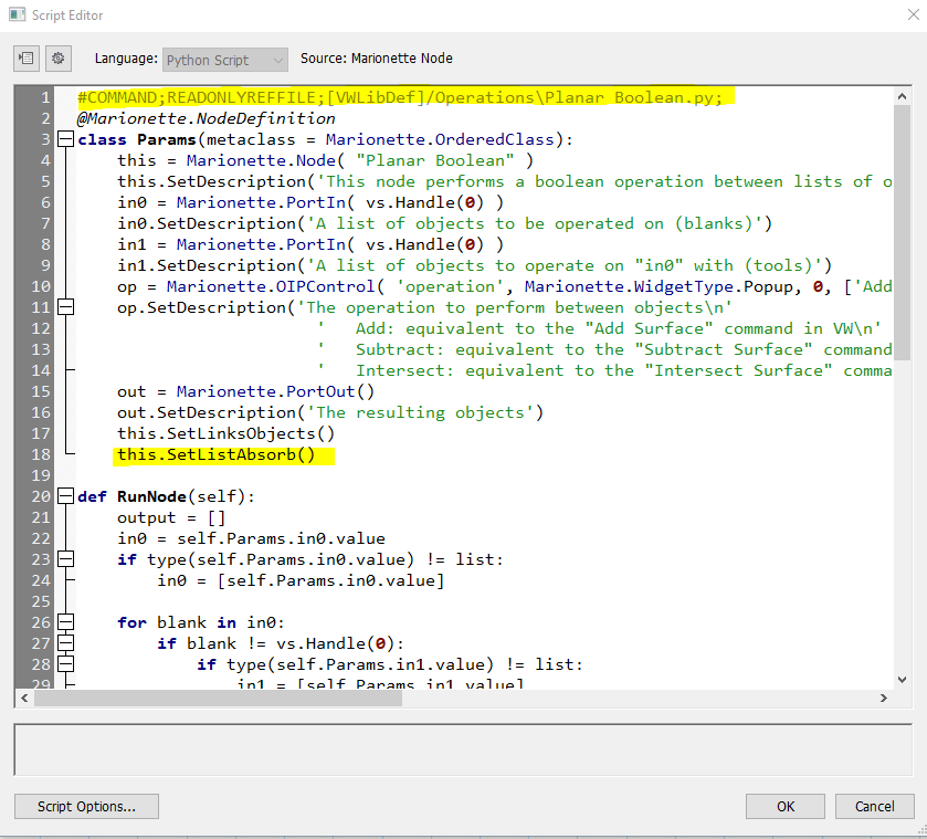
So the problem here is the 'Planar Boolean' node. This node will create every possible combination of the inputs, which is why all of your shapes are adding together. The easiest way to handle this right now would be to enter the script of that node and remove the line 'this.SetListAbsorb()' (you will also need to remove the top line that shows where the referenced python file is). There are a few other ways to handle this, but this would be the most straightforward at this time. I've attached an image. Remove the highlighted text from the script and you should be good to go. We are working on another way to handle cases like this.
-
Here's a very simple example using an existing rectangle and drawing an oval on top of it with the same dimensions using both the name node and the control geometry method. I'm also attaching one of my favorite examples which allows you to reshape a curve and split it into pieces while placing objects along the path using the path as control geometry. You can apply a similar method to create adjustable 'extrude along path' objects (such as for crown molding or baseboards). I'll try to find my existing example of this sometime today. name vs control geometry.vwx MarionetteDivideCurve_MFarrell.vwx
-
This can be avoided if you wrap your network and then select both the object you want for your control geometry AND the wrapper, then right click on the wrapper (with both still selected) and Convert to Marionette Object.
-
Pat, I think those only exist on the 2D chamfer tool. I didn't see this option on the 3D one.

