
Andy Broomell
-
Posts
3,173 -
Joined
-
Last visited
Content Type
Profiles
Forums
Events
Articles
Marionette
Store
Everything posted by Andy Broomell
-

Visibility Tool - Option to Ignore "None" Class
Andy Broomell replied to Andy Broomell's question in Wishlist - Feature and Content Requests
Bump. -
Select a random assortment of objects?
Andy Broomell replied to Andy Broomell's topic in General Discussion
You ask all the good questions! I think avoiding the bias towards one symbol, as you describe, should be avoided if possible. And I hadn't even thought about selecting vs deselecting. If pop-ups are possible, I think input from the user might be the best approach, and would allow for the greatest flexibility. Here's one way I can envision it via deselecting: Select 100 symbols, all Symbol A. Run script. A pop-up asks what percentage to deselect. Type in 33%. I'm left with 66 symbols which I change to Symbol B. Run script again, still with those 66 symbols selected. Type in 50%. I'm left with 33 symbols which I change to Symbol C. This allows you to get roughly even numbers of each symbol (doesn't need to be exactly equal of course). Another variation via selecting: Have 100 instances of Symbol A but none are selected. Run script. A pop-up asks what percentage to select. Type in 33%. 33 symbols are selected which I change to Symbol B. Edit<Invert Selection to switch selection to the remaining 67. Group those 67 then enter the group. Make sure nothing is selected. Run script again. Type in 50%. Change the 34 that become selected to Symbol C. Exit group and ungroup. I'm not sure which approach is more advantageous, aside from the first one being simpler since it doesn't require grouping. I'm sure a wiser mind than mine can think of an even better method -
Basic Tool Pallet and Tool Set Bar always resizing
Andy Broomell replied to mlance's question in Known Issues
Are these custom workspaces that were migrated from previous versions? Today a friend told me how every time she opens Vectorworks her palettes are undocked, resized, and generally buggy. She has to turn each one off via Windows<Palettes, then turn them back on, redock, and resize. (She showed me, and it's definitely buggy.) Obviously this shouldn't be happening, but also her workspace originated in V2011 or older... I'm guessing that might be a factor? I suggested to her it may be time to rebuild her custom workspace from scratch. -
Separation Lines in ClipCube
Andy Broomell replied to Andy Broomell's question in Wishlist - Feature and Content Requests
Bump. I saw both of these issues brought up elsewhere in topics these week. -
Circle tabletop... Oval rug... (apparently it affects Oval Extrudes too)

-
Hmm, I can't seem to get this to deselect objects on layers that aren't Editable; it only deselects the objects on the Active layer. But I might be doing something wrong? (The goal is to be able to leave Layer Options on Show/Snap Others). Thanks!
-
Now that you mention it, I did notice one time recently that the script operates on objects which are "selected" on other layers even when the Layer Options are set to "Show Others" and "Show/Snap" others. In these two cases, selected objects on other layers don't display their highlighting, so it's really easy to accidentally rotate something unintentionally. "Snow/Snap/Others" works as one would expect. Here's a video illustrating what I mean: RotateRandomly.mov (note I'm using a key command for the rotate randomly script... which I've made Cmd+Opt+Shift+?) Is there a way to change "visible selected objects" to "visible, selected, editable objects"? If not, how do you make the ForEachObject criteria be Active layer only?
-
Image Prop & Plant Object Shadows
Andy Broomell replied to willofmaine's topic in General Discussion
In the Resource Manager you'll find a texture for each type of plant. Right click each texture to Edit it, and you'll see that the Reflectivity is probably set to Glow. This means that the texture is self-illuminating and therefore shadows don't show up. Simply turn the Reflectivity to None and you should be good to go. -
This has long frustrated me. Pretty much every file of mine has at least one Light named "x".
-
Tutorial: Elevations and Sections from 3D for Film & TV
Andy Broomell replied to EAlexander's topic in Entertainment
As far as I'm aware the DPI doesn't affect vector geometry, right? I believe Evan's post was primarily dealing with creating vector elevations rather than renderings. But I agree that if you're dealing with anything raster it's important to pay attention to this. -
Tutorial: Elevations and Sections from 3D for Film & TV
Andy Broomell replied to EAlexander's topic in Entertainment
Same here, Evan - I've had your website bookmarked in the 'aspirational' category for a while now Thank you for sharing your tutorial video above. Well-explained, and I think the techniques it outlines are ones that all draftspersons should know. While I use individual aspects of that workflow here and there, for the most part I agree with Kevin & Grant and have embraced the live-viewport-looking-at-the-3D-model approach when it comes to drafting: ^^These pretty much encapsulate my thoughts. I take viewports directly from the 3D geometry whenever I can (with some exceptions outlined later). Reasons include: Revisions. There are always revisions. Always. Just hit update; it's built in to the workflow. I can also go from initial rough drafting to final detailed drafting pretty seamlessly. Less room for error. If any piece of information exists in two unconnected spots I'm bound to forget about it at some point and make an error. I try to never have unconnected duplicate information if I can help it. Speed. This also ties in to the two previous points. I can alter one element in a 3D model, and 10 different viewports can receive that updated information with little effort on my part. And if it takes a moment to update I can go grab a cup of tea :-) Foreground/Background render. Depending on the design I sometimes utilize the ability to add shading to elevations like Kevin and Grant have mentioned, which is built into the viewport method. You can even pull full textures to create a paint/finish elevations. The notion about the computer getting bogged down with live viewports is interesting to me. Updating a Hidden Line viewport can certainly take a beat, but isn't it the same calculation as if you use Convert to Lines? Of course one thing to note is that a Section Viewport has its own "3D Conversion Resolution" setting, while Convert to Lines utilizes the quality setting from Vectorworks Preferences [I tend to keep both at High]. If these are not the same, it's certainly possible that the viewport method may seem slower... But otherwise the calculation speed is the same in either approach, right? And the frequency would be the same, since you only update a viewport if geometry changes, and likewise only go through the manual conversion process again if the geometry changes. So it seems to me like the computer processing aspect would be equal between the two approaches, but I may very well be missing something . Primarily with live viewports, but then the next question is 'where' the viewports are looking, which depends on the circumstances of the design. A few possibilities: Viewports are looking directly at the Design Layer(s) where the design was built and resides. Pretty straightforward... but doesn't work perfectly with all types of designs. This is most suitable for interior designs, box sets, tv shows with lots of walls, etc. But it's not great for, let's say, a musical with lots of individual scenic units, in which case I might do the next following: Each unit within the set is a Symbol that resides initially on one Design Layer within the overall design, and then additionally on a separate Design Layer used only for drafting purposes. On this separate layer it's easy to make viewports of all the different orthographic views you need because you don't have to worry about any of the other scenic elements occluding it. You also don't care about where the unit is on stage, since you only move the one symbol around on your master design layer, but just leave the other symbol at 0,0 on your 'draft' layer. You'll probably find a version of this approach in Grant's files since I think I learned it from him :-) Some combination of both. Depending on the design it might be hard to separate walls into discrete units/symbols as method 2 would require, so the walls might be best drafted via method 1, pulling straight from the master design layer. But then other elements in the same set I'll draft with method 2 where I'll place a Symbol instance on a separate design layer for the conveniences it allows. I flip back and forth between both methods often. A viewport might also look at a 'drafting' design layer where I've drawn out some schematic purely in 2D (or sometimes derived 2D geometry from the 3D model exactly as outlined in the tutorial video above). Conversely, there are a few reasons I can think of to use the "Convert to Lines" method over the "Live Viewport" method. The obvious disadvantage to the Viewport method is that you can't select any of the geometry directly, which can sometimes be problematic: You can't always get the desired granular control over visual attributes when using live viewports. Depending on the design and how picky you want to be about having proper, lineweight-y drafting (which I fully support), it's sometimes necessary to convert to pure 2D so you can do what you need to. Yes, with viewports you can overlay thicker lines in Annotations, and you can change the lineweights of the 3D objects to influence the lineweights in the viewport, but this isn't always enough. A client or vendor may need 2D-only viewport-less vector geometry. I've worked with scene shops who (for various reasons) need to be able to select any and all elements directly, such as lines, section profiles, etc., which you can't do in a viewport. [They may also need my geometry to exist on Design Layers so that they can work on top of it, overlaying their own technical drawings, for example.] In these cases I lay out my sheets entirely on Design Layers, side-by-side (see image below). This is the true old-fashioned way in VW and involves publishing Saved Views. It still works thankfully, though there are other caveats I won't get into. The nature of the object being drafted doesn't lend itself well to 3D, in which case I'll go as far as I can in 3D, do the Convert to Lines process, then continue working in 2D. Here's a quick screenshot of an example where some of the above factors were in play, so everything is laid out on a Design Layer: In fact I really enjoyed laying it out this way because when it came to dimensioning and annotating I could freely pan around and jump between any view seamlessly. No clicking in and out of Annotations constantly. I could drag a drop a note from one view onto another, and it was lovely. But it's becoming more and more rare that I employ this approach. In general I think it's best to be familiar with all possible workflows so you can choose what works best for the particular circumstances of a project, which as we know in the entertainment industry can vary wildly and quickly. Whenever the choice comes down to my own personal preference, the advantages of speed and consistency make live viewports the winner.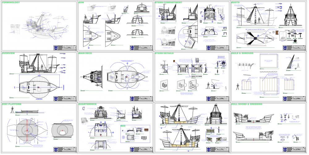
-
Select a random assortment of objects?
Andy Broomell replied to Andy Broomell's topic in General Discussion
BTW- the script wouldn't necessarily have to do any of the actual replacing of symbols. If it just selects the random assortment, I'd still manually do the Replace Symbol command which is fine. Actually, that could make the script useful in other scenarios as well, such as giving different colors or textures to a random selection of objects. Perfection, symmetry, and identicalness are all so easy to achieve in CAD programs. Variation, imperfection, and randomness are a bit more difficult, but can help add realism to renderings. Anything to help automate that is very useful. For example, I use the "Rotate Each Object Randomly" script you wrote all the time -
Select a random assortment of objects?
Andy Broomell replied to Andy Broomell's topic in General Discussion
Just to drive you a little bit more crazy In all honesty, thank you a ton for even being willing to take on these little challenges! No rush on this one; it's a task I do at least once or twice a week, so it will always be useful. I wish I knew the slightest but of scripting otherwise I'd try myself. It's on the list of things to learn! I'm not sure what's meant by "empty" symbol, but it sounds like that's along the right track? A bit over my head I've attached a file with a chunk of seating on the left that's my "starting point" and the same chunk on the right that would be the hypothetical result. Audiences.vwx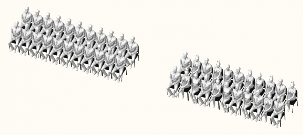
-
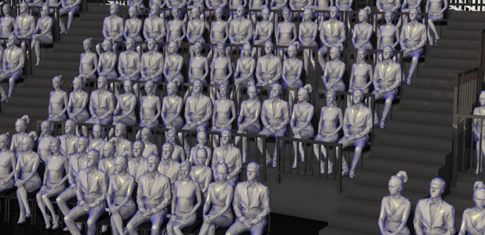
Say for example I have an audience layout that consists of 300 chair symbols (laid out manually, not with the seating layout tool). Inside the 3D component of the chair symbol I have a 3D figure sitting on the chair, since I'll be doing renderings in this document. It looks weird to have an army of 300 identical people in an audience, so I'd like to mix it up between three different chair symbols, each having the same chair but a different 3D figure. All I need to do is utilize the "Replace Symbol" function, but my current workflow involves first having to manually select 100 of the chairs via individual clicking. Then after Replacing Symbol I have to select another hundred. This is very slow. Is there any way, perhaps with a script, to select a third or a half of the objects on the screen randomly? @Pat Stanford Rough idea of result
-
could any one help me in creating leather Texture?
Andy Broomell replied to Rishie's topic in Rendering
Do you have an image of what you're trying to achieve? A piece of furniture perhaps? -
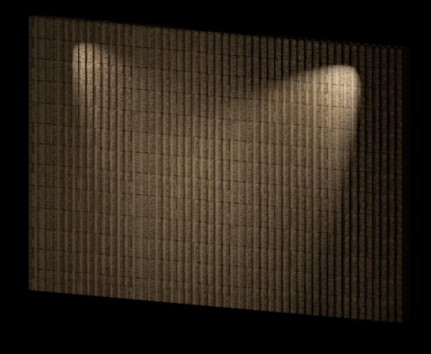
Like this? (I'm not sure that Parallax Mapping existed in VW2015, so the texture might work differently than in 2018). FlutedBlock_v2015.vwx FlutedBlock_v2018.vwx
-
I believe in that example the symbol would be Blue, which indicates Convert to Group. But same concept. Red and Blue symbols are very similar. Blue Converts to Group upon insertion and Red converts to Plug-In Object upon insertion. So let's say for example you use the "Table and Chairs" tool and have set it up with a configuration you want to quickly use again in the future. Save it as a Symbol but check the "Convert to Plug-In Object" checkbox. This will make a Red symbol in the RM. Then whenever you drop this Symbol into your file, or other files, it'll create a "Table and Chairs" with those settings instead of whatever the default settings might have been for that tool. So as Zoomer states, Red Symbols are sort of a way to have Plug-In styles without actually having Plug-In styles. It's more of a Plug-In preset, I suppose. EDIT: To answer the original question, I've never really intentionally utilized them, though they may be useful in some contexts.
-
Agreed! I had the exact same thought when looking at Bruce's thread today
-
Beautiful - Thank you @markdd!!
-
I actually recently wanted to create a symbol count worksheet in 2018, and it seemed to be exponentially more difficult than it was in 2017. Could someone explain the most efficient steps to take in 2018 to get the exact same result as the steps I outlined above for 2017? (Not importing a worksheet but creating one).
-
To full scale or not to full scale?
Andy Broomell replied to MartinFahrer's topic in General Discussion
I should note that there is one client I work with which still requires I use this workflow. I need to submit files which have 2D-only views laid out on Design Layers in the "old style" so that the shop doesn't have to deal with Viewports. This allows them to easily select any individual object (as opposed to linework being tied to 3D geometry via a viewport). Of course I still build 3D models then use "Convert Copy to Lines" all the time. Although it's not a ideal workflow for me, it's definitely the best thing for that particular company and I'm happy Vectorworks has retained this previous workflow. -
Limit to the number of uplights that can be turned on?
Andy Broomell replied to Tony_PSAV_PM's question in Troubleshooting
Or better yet... if you have a Light selected it should automatically be considered one of the 8. -
Limit to the number of uplights that can be turned on?
Andy Broomell replied to Tony_PSAV_PM's question in Troubleshooting
You're completely right. I shouldn't post so late at night, haha. But what I think I meant to say is that I wish there were more logic behind which 8 it chooses when you have a lot of lights on. For example, if you could simply send a light to front to make it be one of the 8 that are on, that would be very convenient. I'd love to not have to turn all my lights off and on all the time. -
Limit to the number of uplights that can be turned on?
Andy Broomell replied to Tony_PSAV_PM's question in Troubleshooting
Now if only Vectorworks let you control WHICH 8 lights were displaying, I'd be a happy camper. -
A “by current class” choice in symbols
Andy Broomell replied to Andrew Davies's question in Wishlist - Feature and Content Requests
...the one time I absolutely agree with this sentence 😆