scottmoore
-
Posts
673 -
Joined
-
Last visited
Content Type
Profiles
Forums
Events
Articles
Marionette
Store
Everything posted by scottmoore
-

Saved Views - classes turned off
scottmoore replied to James Dawson Design's topic in General Discussion
For any embedded classes created by symbols and PIOs that you use regularly, I suggest bringing them into your template file and get all of your visibilities set in saved views in advance. This way you can avoid tedious work while designing or drafting. You can always purge later if you desire. -
I have a pair of 35” curved and I love it. I have them set up somewhat asymmetrically. In other words, the bezel is not centered but instead off to my right. My main screen is just off center to my left so that is not uncomfortable at all. Currently I like having information split up on separate screens. That said, a 49” might be quite nice!
-
Video images are via textures. Add an image to the “color shader”. Apparently the plug automatically adds a glow attribute to any texture that’s used for video, but I always do that myself so I can adjust the overall brightness. I typically start at 125% and then look at results. as far as mapping is concerned, the plug in will default to scaling the image to the overall width, you can adjust scaling and position from there. Keep in mind, it will NOT asymmetrically scale. In your case, you have a wide format image, wider than 16:9 for instance. Ideally you would want either an image that is proportionally correct for your output screen ratio, just like you will have for actual event content. Alternately, you need a screen image that can scale up and not lose any important visual content. in your case, a really quick fix would be to import that image into your drawing, then create a square the same width of the image, center it on your image and move it to the back. The square should be made the same color as the existing background. (In the color attribute pallets use “custom color” and you will find an eye dropper that can sample the color you need for fill). Take a screen shot of the square. Now replace the color shader of your existing screen graphic and your black background will fill the top and bottom of the screen. Sounds like a lot to do, but should only take a minute.
-
Thanks for the plug Grant! During the pandemic I started a new library of more detailed symbols since many users are rendering in other applications that are much quicker at processing higher polygon counts. Then the pandemic ended and I have been slammed, but at some point I will have them available. Here are a couple of images of a vintage style drum kit. These are VWX symbols that are textured in VWX and then rendered in Capture. At 4k the renders took less than 5 sec each. These are scaled back to upload.


-
That is the same thing I have been seeing. The process is exacerbated greatly when a user is on a slow internet connection. On a few occasions I have actually seen the temp file that VWX creates (.tmp perhaps? I don't recall), which really should only happen in the background from what I understand. I've stared at my dropbox folder and have seen it pop up for a split second and then disappear. On one occasion it popped up, replacing the .vwxp file and never left. That's how i figured out there was such a thing. Regardless, we seem to be moving along ok at this point. There are a lot of users on this file which also creates a bit of a challenge.
-
Rick, thanks. I can imagine that someone may have neglected to trash their working file after a reset and seeing an issue. That does make sense. What I don’t understand is what causes that in the first place. This particular project has been a bit of a hassle for some reason.
-
Pat, sorry for the confusion. “Working on a project file” meaning that we are using a project file. Everyone is indeed using their working files. I can imagine that someone has used an older working file once the project file was reset which can cause issues, just not sure how this happens in the first place.
-
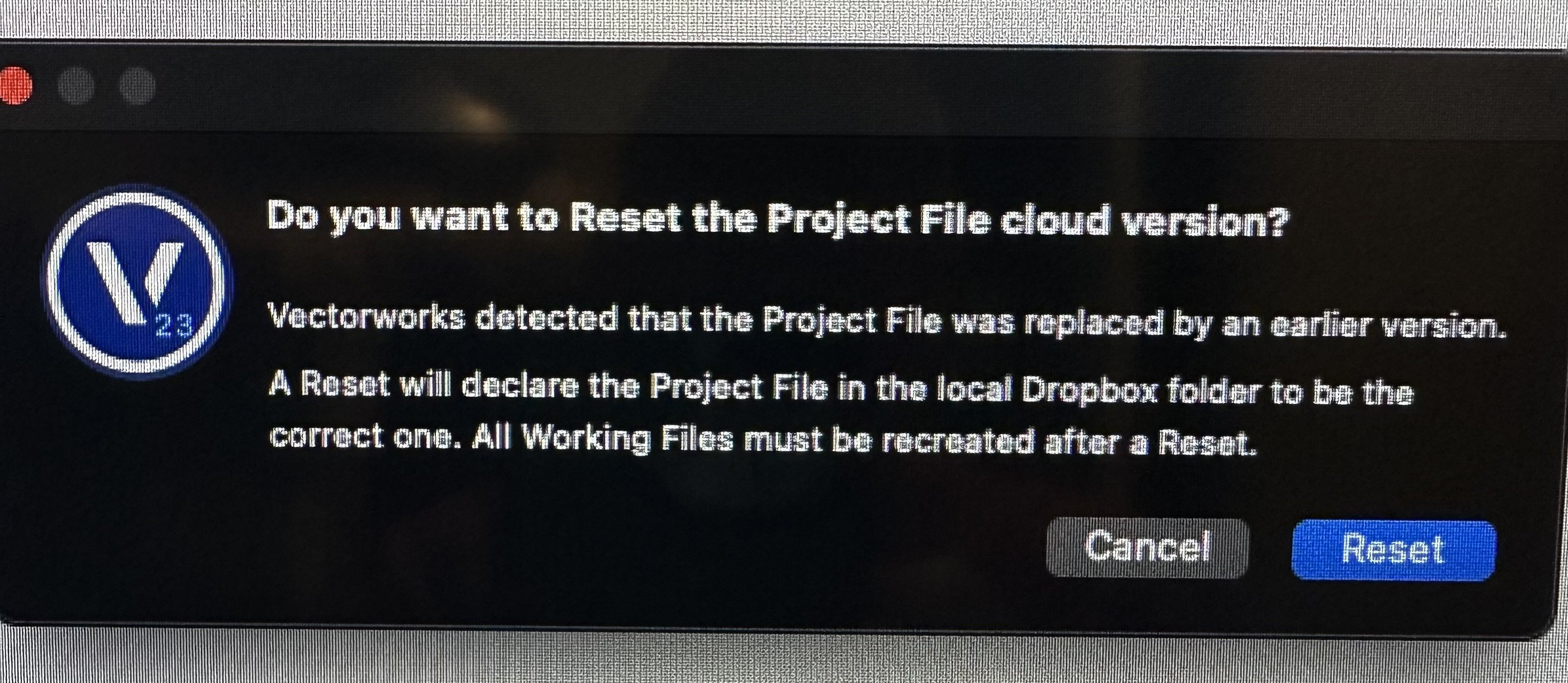
I am working on a project file, shared on Dropbox and we have been getting the “reset the project file” notification. I have reset it, the lead administrator has reset it, and I am still getting this message. Any suggestions? I am guessing it is time to start using the cloud service for hosting.

-
Streamdeck integration.
scottmoore replied to Matster's question in Wishlist - Feature and Content Requests
Sweet -
Arena Model Available
scottmoore replied to scottmoore's topic in 3rd Party Services, Products and Events
Jake, thank you for the kind words. As to the suggestion, I love the idea of a completely parametric arena model, but I have no coding skills whatsoever save for manipulating some existing scripts to do very simple tasks. Maybe Andy Dunning and I can partner on something, but neither of us have any spare time! What I have done in the past for smaller arenas is turn off the 200 level, add a wall around the perimeter 100 level and lower the steel and ceiling. Takes a couple of minutes. -
He’s looking for Ribbon Lifts. I believe formerly Stardrive.
-
Streamdeck integration.
scottmoore replied to Matster's question in Wishlist - Feature and Content Requests
There are a ton of usable images of the Utah Teapot online. Does it have to be SVG on the Windows platform? I’ve used JPG and PNG almost exclusively on mine. (Mac OS) -
Speaker Array - Rigging Frames & Pull-Back Bar
scottmoore replied to Mark Aceto's topic in Entertainment
Agreed -
Speaker Array - Rigging Frames & Pull-Back Bar
scottmoore replied to Mark Aceto's topic in Entertainment
Understood. I am of the opinion that it’s better to rely on the manufacturer’s calculations than hope that the data entered into BraceWorks and the resulting calculation is correct. Any reputable audio vendor using major manufacturers equipment will utilize an application that calculates those weights specific to which hole is selected on the bumper, the particular angles of each cabinet and whether or not there is a tilt back bumper underneath. Most riggers and engineering firms would be more apt to look at these numbers I believe. I am just concerned that we open up a potentially huge can of liability worms when we try to make VWX be the end all be all of production work. I love the idea of it and am seriously impressed with your work and attention to detail (as always), but we all need to be careful. -
Speaker Array - Rigging Frames & Pull-Back Bar
scottmoore replied to Mark Aceto's topic in Entertainment
Great work as always guys. Quick question regarding weight calculations and your processes on projects: do you take the BraceWorks calculated weight and compare that to the manufacturers data provided by your audio vendor? To my way of thinking, one would be better served to input the data from the manufacturer than relying on BraceWorks, especially if the arrays are hanging from dedicated hoists and not attached, either by hoist or dead hung, to a truss structure. Just curious. -
Not entirely sure how to do some of this with a StreamDeck, however, this is a great usage for saved views. When you save a “saved view” it doesn’t have to save the view orientation at all. Of course you can if you want to, but what is really cool is setting up the layers and classes you want visible AND which layers and classes are ACTIVE as well as the layer/class option settings. In your template, you would just go to your saved view “Trussing” and start dropping in truss. Because you saved the proper information, the symbol automatically assigns to the “truss” class on the “rigging” layer. Go to the “hoist” saved view and any hoists inserted will be in the right class and layer. This process ensures all the correct embedded classes are on/off as well. no more “why aren’t my label legends showing up?” Keep going with “flown lighting”, “floor lighting”, “audio”, “video” “staging” etc saved views and your workflow gets streamlined really quickly. Spend an afternoon creating these saved views in your template and you will be amazed at how much quicker you can get things done. Side note: that is why I have the “none class” tool on my StreamDeck. Since various classes have been made active at any time in my workflow, sometimes I just need to go back to the none class to create a symbol. Just a key press now. I get dozens of VWX files from all sorts of people and hardly any of them ever have saved views. How much time do people spend turning things on and off to work on a drawing? Maybe people just leave everything on all the time?
-
I believe so, but that is the part that reverse engineering was not helping me to figure out.
-
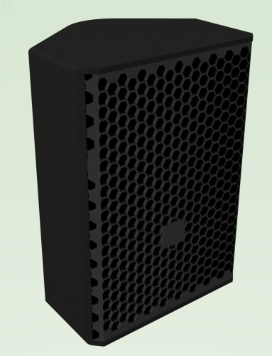
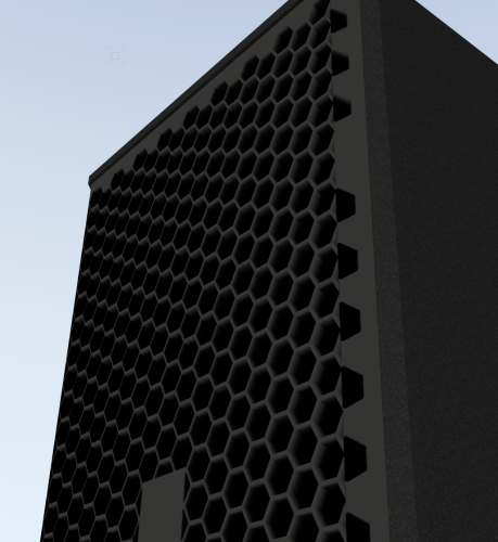
Patrick, Using the bump shader is probably the way to go. I figured that out for a speaker grill I was working on a few months ago as a proof of concept. As with so many things, I don't entirely recall how I did it, and reverse engineering didn't really help with trying to create your grid. It's on the tip of my brian somewhere. The point of the image below is this is a flat surface with a texture with the bump shader enabled. It is not truly a 3 dimensional surface. pretty much what you are looking to do except with hexagons.
-
And I appreciate the plug Peter.
-
MacOS indeed. I’ve been using Chrome but will check and see.
-
My opinion is this is a bug. I am on 2023 and it has not happened in quite a while, but it would happen fairly frequently previously. If I recall, it happened almost every time I published. But it would happen randomly as well. Once that happened, a restart would solve it. It was a huge hassle. By the way, using the space bar to temporarily invoke the “hand” tool is called “boomerang”.
-
@Pat Stanford very informative and timely. A colleague of mine asked about this on Friday and I couldn’t explain it very well. This is precisely what I would have been looking for.
-
The Transformative Power of NURBS Modelling
scottmoore replied to VIRTUALENVIRONS's topic in General Discussion
When I can get things to slow down a bit, I am going to look forward to diving into this! -
@jeff prince I don’t know that a line type will translate to CNC output. Typically line types are not recognized. As to symbols for the clips, that is a great idea, however, that is how I initially started doing these kinds of projects some time ago and it turned out to be far more cumbersome than the trimming. Curvilinear forms are always problematic. Ellipses even more so. I have a couple of hours left on this project and one more to complete in the next week. I’ll get through it, but what should be a fairly simple process just becomes a little annoying.
-
Reviving an old thread. Why can't the trim tool work as expected? I do lots of CAD files that involve channels with widened areas for mounting clips. I create the first wall of a channel with arcs, straight lines or whatever tool is necessary. I use the offset tool to create the opposing wall of the channel. I again use the offset tool again to create a concentric set of geometry for both walls of the channel that will define the extents of the clip mounting location. I use the double line polygon tool in the "create lines" mode to determine the end of the clip mounting locations. Then it is a simple matter to use the trim tool to leave the proper clip mounting location; except it SELDOM works correctly. Here is the first step prior to trimming: After I have used the trim tool: Notice one of the four clip locations (top right) actually worked correctly. One clip is missing one line, one is missing three and one is missing four. Here is what it looks like after I fix it by manually drawing lines: I have sorted out the order of operations to make the fix simple, but when there are hundreds of these clips to draw on any project, this becomes VERY tedious. By the way, this project is very curvilinear in nature, but the same is true when it is simple arcs, circles and, to a lesser extent, straight lines.