All Activity
- Past hour
-
Also - If hardscape 3d display curvature is is changed via the simplification tolerance, a double click of the Hardscape launches the Reshape tool and reveals vertices of the Path (no need to right click>edit path) for edit - not converted to some polygon with many facets. Edits can be made in 3d views as if editing that simple 2d polyline. Changing the Simplification Tolerance in the OIP does not affect the vertex count near bottom of the OIP. eg in my example above, the vertex count is 8 in each iteration of the simplification value. -B
- Today
-
Ok. Then I paste the symbol back in and then save that file to my favourites or wherever. Thank you.
-
In my tests - Adjustments to the 3d simplification tolerance, eg in Hardscape OIP, do not affect the source object geometry. Those original Arcs, Bezier and spline curves in the source polyline are present for edit via right click Edit Path pane. TopPlan always displays the curves as the source obj . Perhaps others can comment on performance and print/save issues of complex files with super low tolerance settings for such DTMs and site mods? I don't have any big, complex files to compare. -B
-

'Proposed Contours' not working as expected in Site Model
Jeff Prince replied to nicovlogg's question in Troubleshooting
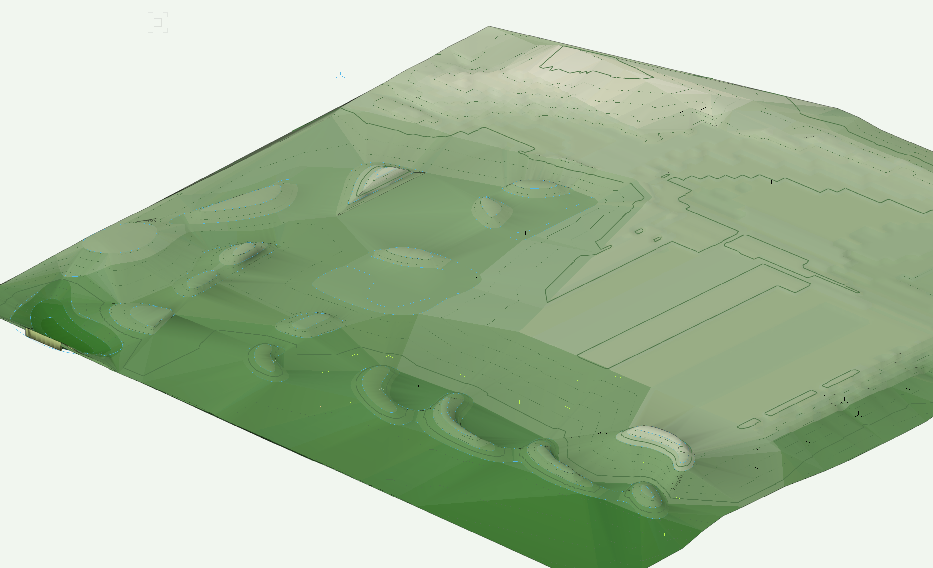
Well, I suppose if you mean all of your existing contours have the same elevation of -5800, then I suppose your are correct 🙂 See this video for an explanation of why your model is misbehaving... flat as a pancake-lr.mp4 You are missing grade limits in that image where your contours look like vertical sided pits. Site modeling is only as good as the data you feed it. It's easy to get lost in all of this, happens to the best of us. Break it down into simple steps and check your work if things go wrong, usually the issue will be evident. -
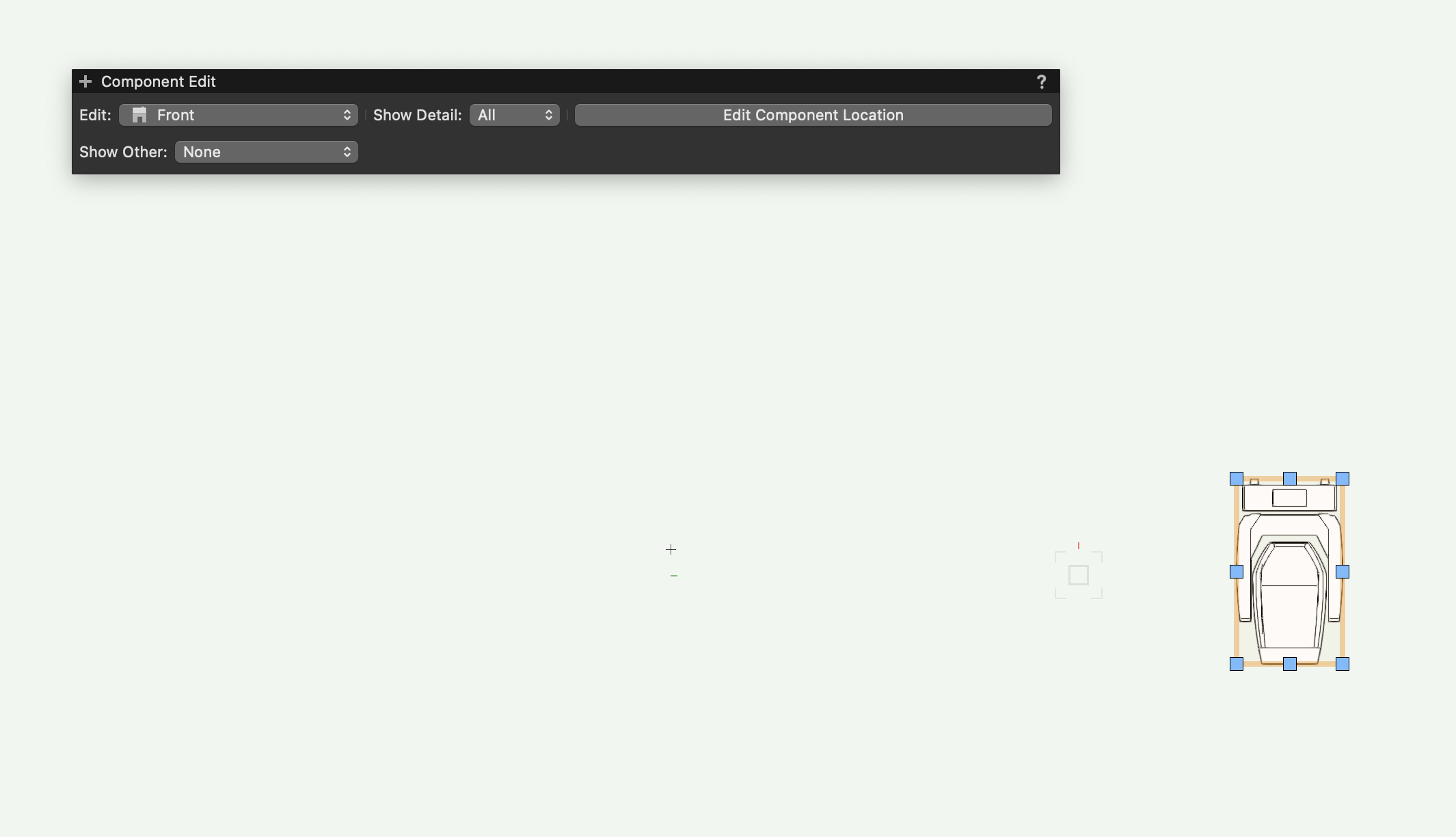
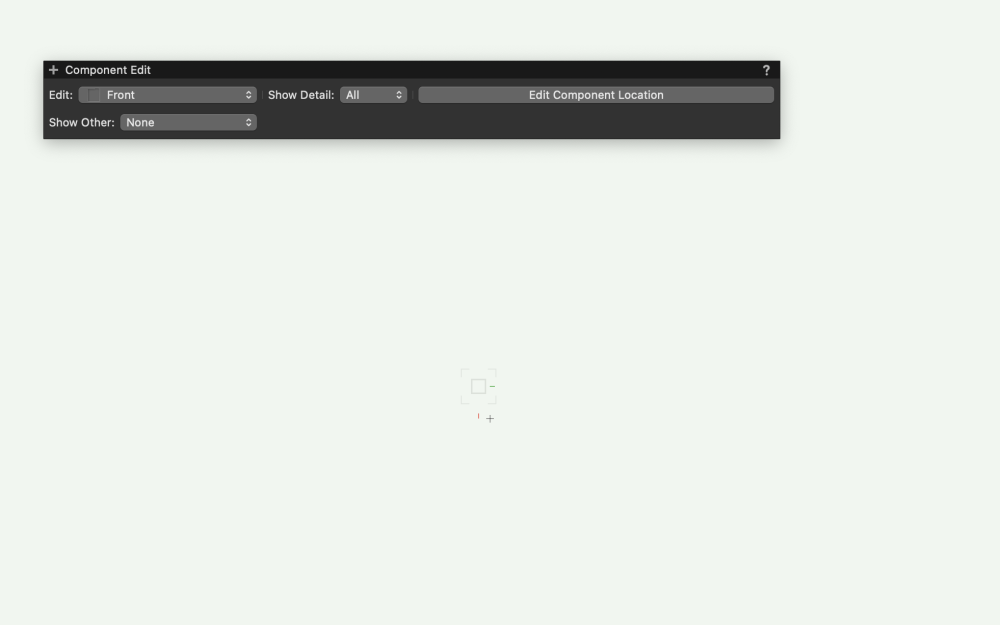
In the Component Edit Palette you need to change the view in the Edit field to Top. Just click on the double arrow where it says Front and you should see an option to change to top.
-
Paul Sadly, tutorials are above my pay grade 🙂 That said, if anyone had a specific problem procuring this, I would be happy to chime in.
-
@JustinVH I'm sorry to come back to you on this, but I get so faar and then it goes sideways. I am clear up to the point when you say ' How do I get back to the 2D side of things? Thank you, Iain

-
Just thinking Kevin, why don't you do a tutorial on this for the Forum, I can't be the only one who would be interested.
-

'Proposed Contours' not working as expected in Site Model
nicovlogg replied to nicovlogg's question in Troubleshooting
Copying the site modifiers from your file and using them on my newly recreated file, I get the following result: Rather than the smooth edges I see on yours Smoothing has been set to 90degrees, so it's something else that I'm missing.
-
Hi Kevin, How are things? I just wanted to give @lkr241 something to work with. The texture was the critical part. The models above involve more than one texture map, but they all come from the NASA website. Thanks for your offer, I can always count on you. I have reacquainted myself with VW texture mapping to a point, I can do the basics, but there is really no point for me to learn more. regards.....Paul
-
Paul in reference to you query about mapping and closing a texture map to an object, like a sphere, I have found you need to do a little math. Meaning, you need to know the exact circumstance of the object, then match that to the width of the image….if that makes sense. If you are having trouble getting it to work perhaps send me a direct message with the object and the image and I can have a go, then explain how it works.
-
 tysonbrooks joined the community
 -
 Hi Jesse, Thanks so much for building this - I'm looking forward to using it. I noticed that this tool doesn't work on referenced Viewports placed in a design layer. Is that something you can confirm? Would you consider expanding the capabilities to include this? Cheers, Nic
 -
'Proposed Contours' not working as expected in Site Model
nicovlogg replied to nicovlogg's question in Troubleshooting
I think we're missing each other - I have an existing site file created using points. According to my understanding, the correct way to edit it post VW2021 is to use the 'edit proposed contours' command - you can see the suggestion here: https://app-help.vectorworks.net/2021/eng/VW2021_Guide/SiteModel1/Creating_a_contour.htm#XREF_15642_Creating_a_Contour The proposed contours do have elevation - is the missing link the grade modifier? Even adding that, I get an essentially random landscape as a result, as below, that has nothing to do with the new contours I've drawn in.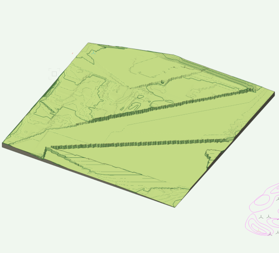
-

Exporting to Old Version without Access to New Version
michaelk replied to EmilyArch's question in Troubleshooting
Rylevang 3B · D 056 · A 7.10 · Oversigt · Skabe v2024 v2021.vwx -
'Proposed Contours' not working as expected in Site Model
Jeff Prince replied to nicovlogg's question in Troubleshooting
You can't get it to work because your existing contours aren't at the correct elevation and you didn't have a grade limit modifier....It really has nothing to do with the method used to add the proposed contours. I don't recall hearing anyone at Vectorworks claiming anything is superior, they seems to be a bit agnostic on methodology. Can you point out where you heard that? I've been beating the drum for years that people should use points instead of contours. Why, because contours are imaginary and points are real. You can make your own imaginary contours from real points. Your model will be more accurate and operate faster as a result. -
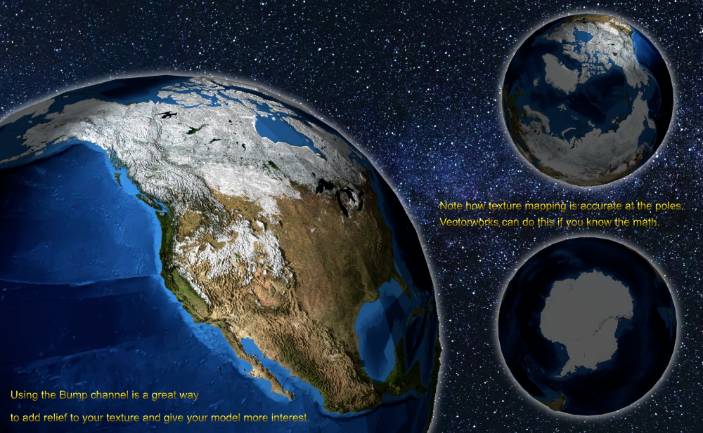
I got these maps off the NASA website several years ago, 2016 or so. They include the Hi clouds, etc. You might think the first one was done with the AI Visualizer, but just C4D. They are/were Lo res or Hi res. No reason why they could not be used in VW's. If you notice continental U.S.A. they have light maps of the cities and towns.


-
 AKI NAGAI joined the community
 -
'Proposed Contours' not working as expected in Site Model
nicovlogg replied to nicovlogg's question in Troubleshooting
Thank you @Jeff Prince, this is exactly what I'm looking for! I understand your process and stumbled onto something similar, but I should note that in the Vectorworks guide they do not suggest using site modifiers and suggest editing the proposed contours, so I followed that process. Is there a reason why I can't get it to work that way or a specific reason why that process is suggested by them as being superior?- 8 replies
-
- 1
-

-
- site model
- proposed
- (and 3 more)
-
Oh Man, thank you for posting. This is going to be a game changer. Thanks @Jesse Cogswell for building this!
-
How do you close a spherical map in VW's? Scaling did not seem to work?
-
Resolution of geoimage keeps dropping with DTM update
Jeff Prince replied to Christopher Rowe's topic in Site Design
You can employ a trick here to avoid the refreshing of geoimages... Set up a geoimage which matches the rectangular extents of your site model. Ungroup it. Build a texture using this image and use the X dimension of the rectangular extents for the texture size. Apply that to the site model using the texture tab in the OIP. This will prevent geoimage refreshes and other crazy behavior. This method also provides a pathway which allows you to edit the geoimage to improve the quality in a photo editor. -
'Proposed Contours' not working as expected in Site Model
Jeff Prince replied to nicovlogg's question in Troubleshooting
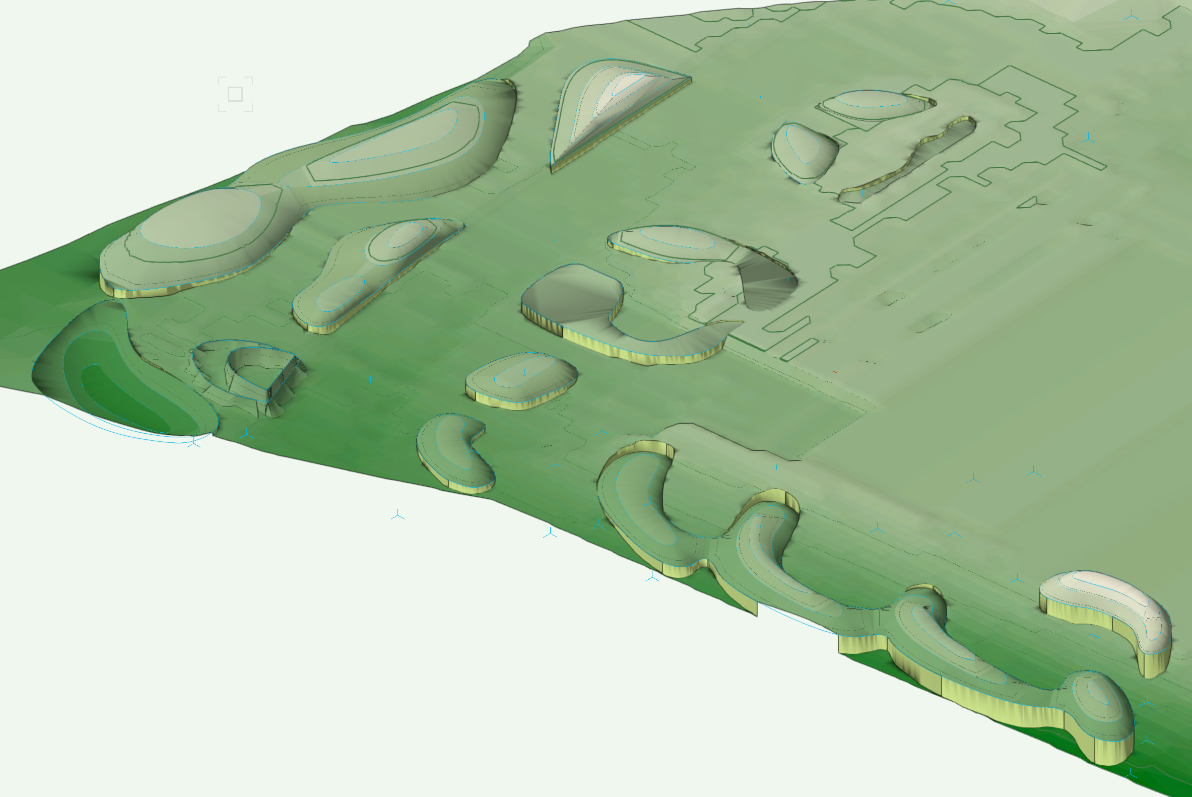
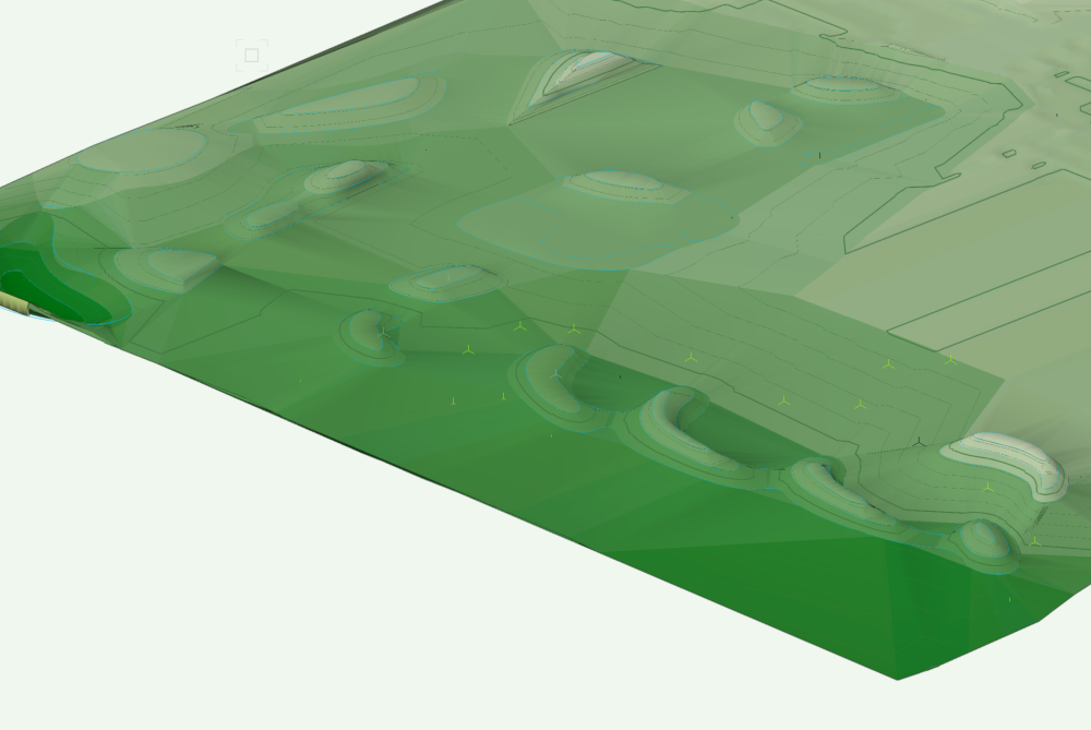
#1 - You don't need to use existing contours for your existing conditions when you have been supplied points. Just grab the points and make and existing site model from them. Next, draw a grade limit around your proposed contours to define the extents you will allow Vectorworks to resolve the grade. Add your 3D Polys representing your proposed contours to the Site-DTM-Modifier class. Set your model to Display proposed in 3D and 2D. Update the site model. You should then see something like this which features burns and swales fitted to your proposed contours. The file you posted shows something similar at the far right, but your existing contours lost their z elevation. This happened sometime around your example named "PROPOSED SITE (CONTOUR EDITED)". Another reason not to use/generate contours when you have points, you can make mistakes without realizing it. Flip your file up into Front View and you will see what I'm talking about... you contours are suddenly flat. Attached is a fixed version of the file for reference. Site Modelling-fixed.vwx
-
 Hmm okay - As I think about it that makes sense - I will have to experiment how to better organize this file then and maintain the Stories in our drawing so that our coordination file back to Revit via IFC works Appreciate you confirming that it is expected and Im not losing my mind entirely
 -
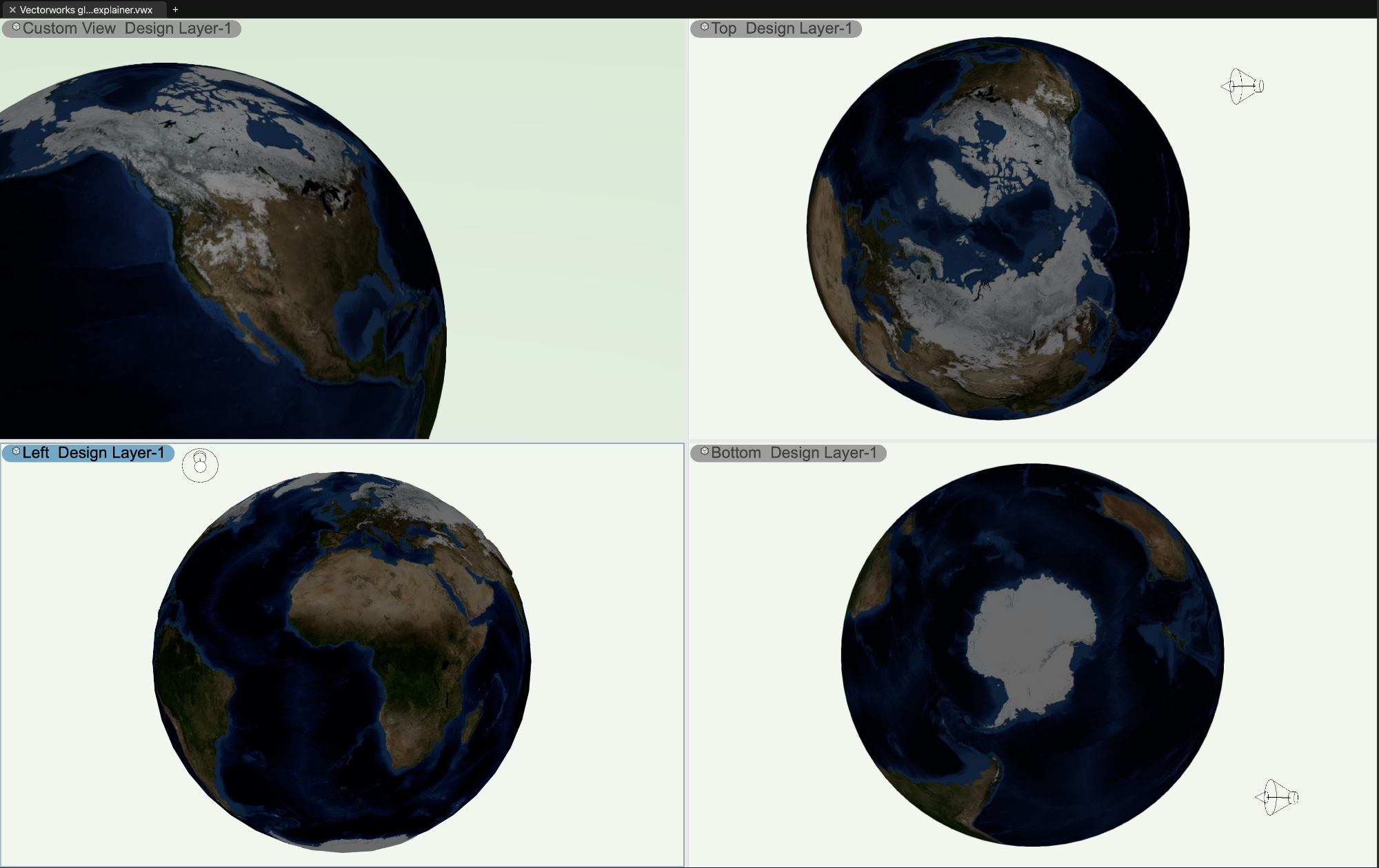
I've always been partial to globes with a bit of raised relief myself... Just make a Vectorworks sphere. Then, make a texture from an image. The best results use an image made from equirectangular projection. Finally, texture the sphere using spherical mapping. The trick to accurately scaling and placing the texture involves Pi and the length of a 90 degree arc based on your model size. The previous examples here by @Kevin K and @VIRTUALENVIRONS may be salvageable in that regard, I don't know where they got their textures. And yes, I did do it in Vectorworks...

-
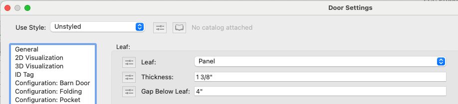
Thank you. @M5d and @Tom W.. Interestingly. VW2024 now includes an option for gap below leaf, which did not exist in VW2023. For whatever reason, I can manage Windoor for windows, but I absolutely can't deal with Windoor for doors. Something about that tool is profoundly counterintuitive at times.
-
Thank you very much, I look forward to your feedback. I will try jdlang19's suggestion and report back.