Search the Community
Showing results for tags 'styles'.
Found 14 results
-
 Detail callout markers (DCMs) have three basic parts - The bit I've made red above, which I'll call the "crop box". The line colour, type, thickness and fill of this are controlled per instance, by changing the object's attributes in the attributes panel. If the DCM is given a certain class, then the attributes of this "crop box" can be set to be by class. The shape of this crop box is essentially drawn per instance. - The bit I've made green which VW calls the "leader (and shoulder?)". The attributes of this line can be controlled per instance using the DCM's OIP, or they can be controlled by a DCM style. - The bit I've made black I'll call the "marker" and the layout and appearance of this can be controlled by style What I'd like: 1) The attributes, and basic shape of the "crop box" should be included in the things that can be controlled by style. Why would I want to control the leader & shoulder by style, but not the crop box? It doesn't make sense. At the moment, to get a reasonably consistent appearance for all of these objects I have to do it using a special class. 2) If "rounded rectangle" is to be one of the shapes we can use for the crop box, then the radius of the corner fillets needs to be independent of the scale of the viewport I'm using it on. That is, whatever value I give for the fillet radius needs to produce the same result whether I'm using it on a 1:100 or 1:2 scale sheet layer viewport. I see no reason why it is useful to have it relative to the scale of the viewport. 3) If "rounded rectangle" is to be one of the shapes we can use, and especially if it's not included in the things we can control by style, then there needs to be an easy way of retrospectively changing the radius of those corner fillets. At the moment it's unintuitive and convoluted, and involves changing each vertex individually using the "change vertex mode" of the reshape tool.
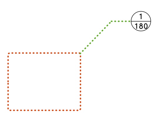
- 4 replies
-
- 14
-

-
- detail callout
- style
- (and 1 more)
-

Repetitive Unit Tool - Styles
rudybeuc@gmail.com posted a question in Wishlist - Feature and Content Requests
Styles for the repetitive unit tool. That way I could build up a library for detailing purposes. Thanks, Rudy Beuc.thumb.png.e97bef5e54ee86a107ec75f72db60dfa.png)
-
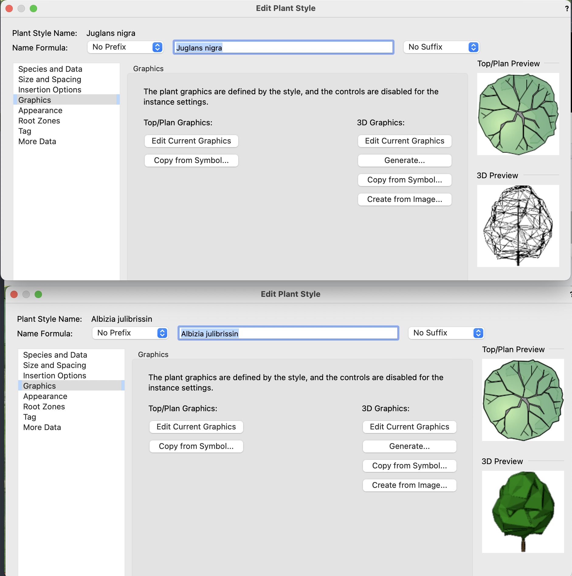
Hi, I was wondering if anyone could tell me what's going on. I'm using the plant tool, adding some new plants as I go.. and having no trouble using "Generate" in the Edit Plant Style > Graphics > 3D Graphics to create some models for the trees. ..until suddenly they no longer appear as normal shaded models, but instead only as wireframe. All the options (volume, shell etc are affected). I have no idea why. I didn't change any graphics/render settings. Now every time I go to set that, they only show as wireframes. I can view the previous ones I did as shaded models, but if I go to edit them they will only give me wireframe, so I have to cancel to back out. I can't see any 'setting' that makes them appear differently, and I tried closing and restarting to no avail. Has anyone had this before?

-
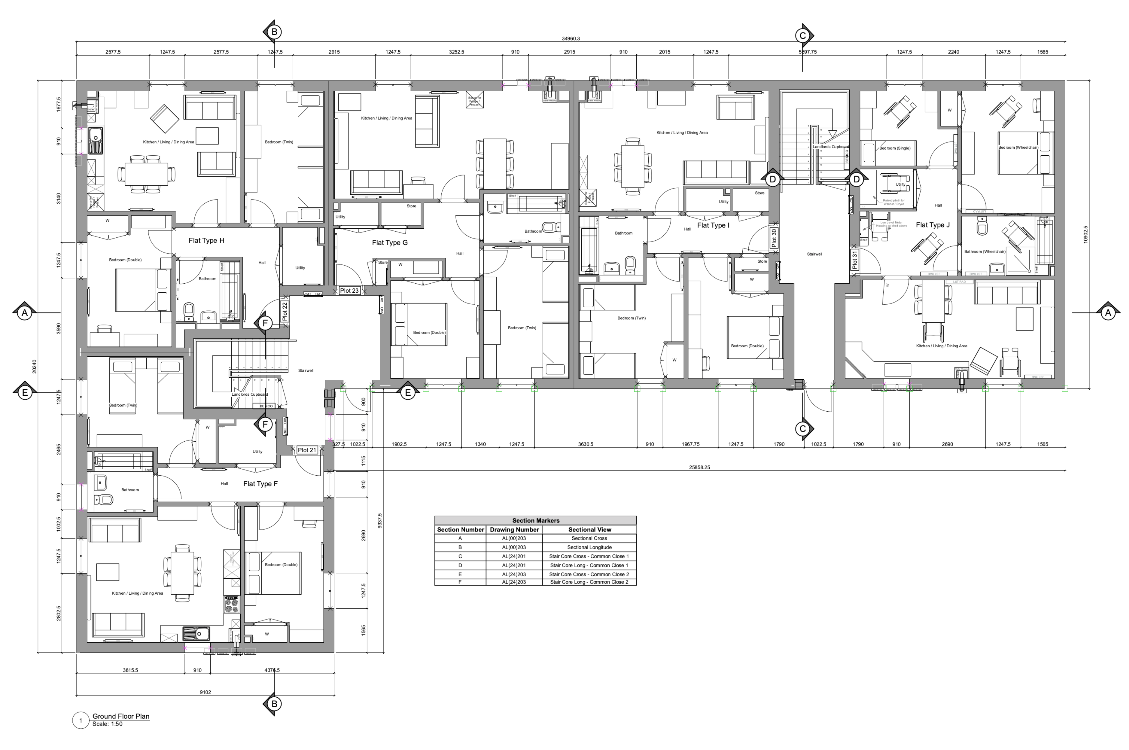
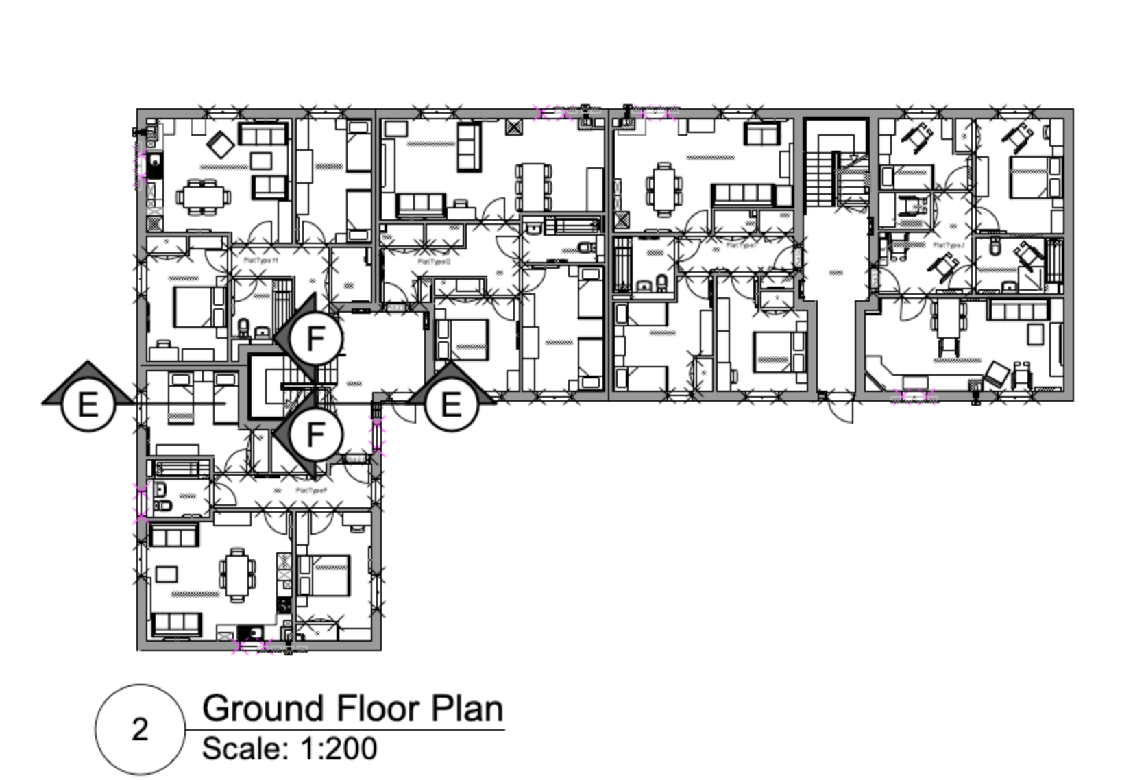
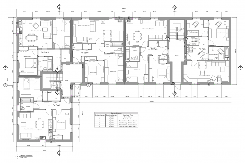
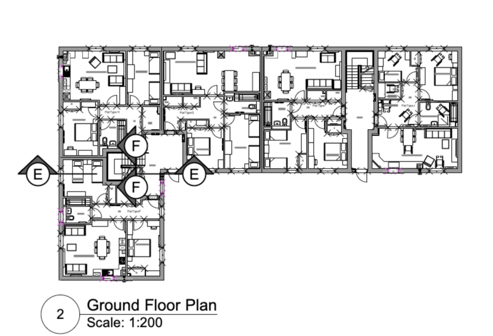
Hoping someone can help with this and we're not missing something obvious. When using coordinated section markers on a plan viewport (1:50) we also show these on the section sheet layer adjacent to the associated section viewport in a contextual plan viewport at a smaller scale (e.g. 1:200) - to allow those reading the drawing to easily identify where a section is taken if reading the section drawing in isolation. Our issue is that the scale of the section markers on the 1:200 scale context viewport appears to be a universal setting across all instances of the marker that are associated with that particular section viewport, meaning they show as either impractically large on the context plan (as shown below) or too small on the main plan if scaled to suit the context plan. Trying to scale markers/symbols etc. in the Advanced Properties for the viewport doesn't appear to affect them and if we change the scale factor for the marker in the annotation layer of one viewport it affects the markers in all other viewports. Is there a way to individually scale these markers for legibility? We are currently working off VW 2022 SP1.1 - While we are aware that SP2.1 is the latest version, there is a known issue with wall hole components of symbols attached to walls that is yet to be fixed.
-
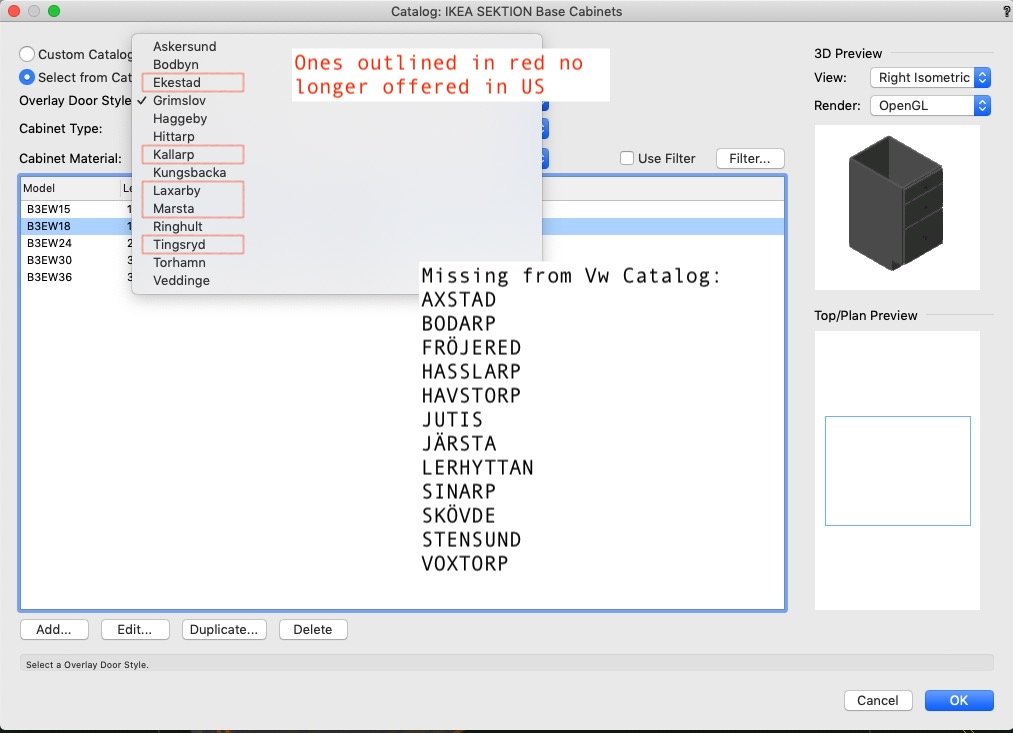
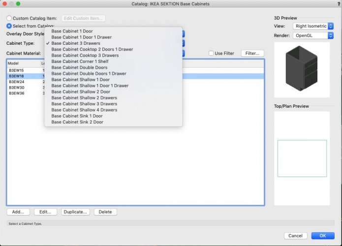
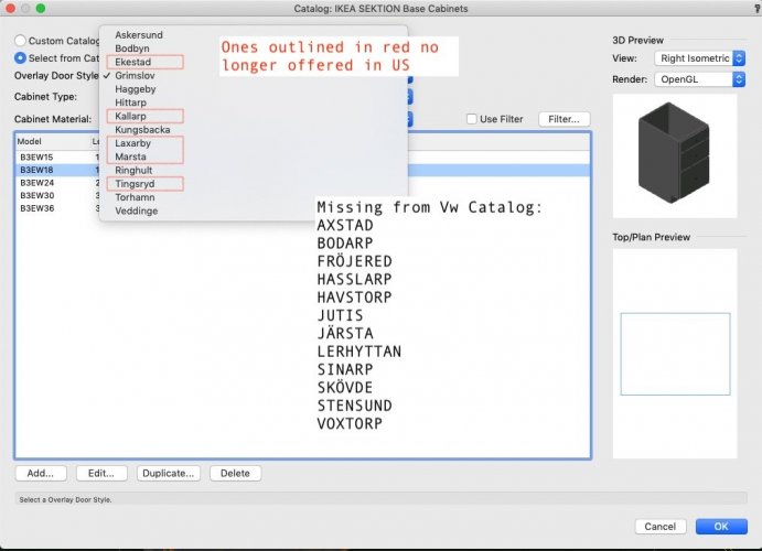
 The VW-provided IKEA U.S. SEKTION Cabinet Styles for Base, Wall, and Utility cabinets (provided in the Premium Library file /Objects - Architecture/Kitchen Typical Layouts.vwx) should be updated to include the entire current 2021-2022 IKEA SEKTION product line. For example, Base Cabinets with 4 drawers (B4E) and 6 drawers (B6E) are not available in the Vw Library (see attached image). I can duplicate the Vw Catalog entry to create my own 4 drawer cabinet, but the drawer heights are drawn as all equal height, not with a deeper bottom drawer. Additionally, the door styles should be updated to reflect the 2021-2022 current IKEA U.S. product line, multiple styles are missing from the catalog and there are door styles included in the Vw catalog which are no longer offered in the U.S. (perhaps in other markets).
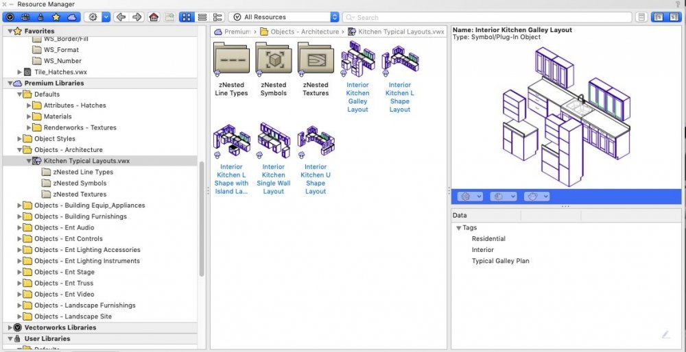
- 1 reply
-
- 4
-
-
- cabinet styles
- ikea
- (and 3 more)
-
We have hundreds of WinDoor symbols [Don't even ask!!!] - well, I say "symbols", but they have been saved as PIOs. What I want to do is create a symbol with a WinDoor Style and save it to the Resource Manager... Fine. I can do that, but when I use it it comes in as a symbol and to make any changes (outside of the Style) we have to explode it. Once exploded, it does however still have the correct Style attached. If I change the symbols to PIOs, everything looks great - when I place it, it is nicely exploded and I can change the form, willy nilly. BUT HOLD ON... it has lost the Style that I assigned to it and it has become its own WinDoor Style! Is anyone using WinDoor Styles effectively? Surely placing a symbol doesn't involve having to explode it and if it is a PIO instead, I would have to replace the style of every WinDoor element that I place so that it is linked to a "Parent". Please identify my stupidity! What am I missing???
-
I am resubmitting this. Now that we have wall styles and door and window styles - we need Viewport Styles. The would work in the same way - where certain attributes are controlled by style and others by instance. Really I want to set up Plan Style, an RCP Style, a Furniture Plan style, etc. Then later when we realize we need to turn on the sprinkler riser class on the plan - we do not have to go to all 30 plans to make that change - we can make the change to the style and all viewports would update automatically. Or if we need to make a class override on all plans to show...something - do that globally to the style.
-
I am trying to write a marionette script that will place a selected titleblock border style on a selection/all of the sheet layers in a file. Is this possible? Struggling to figure it out. I have already created a script that can create all of the sheet layers I may need for a project automatically, but now I am trying to figure out the next steps to make sheet setup easier and faster. Some of the other help items I need are: A node to adjust the sheet size of selected/all sheet layers...preferably from a dropdown list of available sizes? Eventually...how to place viewports on all of the sheets, given crop objects. I'm currently studying the Automated Layout post by @DomC which is what triggered this whole light bulb in the first place. I am just thinking about all of the other objects I could add to make this more powerful How to manage viewport rotation to adjust to the page? How to place Drawing Labels in the Viewport Annotations of the viewports placed above in specific locations relative to the viewport crop? How to place scale bars in the viewport annotations in specific locations relative to the viewport crop/drawing label? How to place North Arrow symbols in the viewport annotations relative to the drawing label/scale bar and that adjust for the rotation of the viewport? How to Control the Visibilities of the Viewport (both classes and layers) by referencing Saved Views visibility states? There are tremendous opportunities here to automate a very time consuming task when there are 10s of 100s of sheet layers and viewports. Excited and hoping someone is willing to provide some assistance. Thanks.
-

Hardscapes and Landscape Areas - Styles
ericjhberg posted a question in Wishlist - Feature and Content Requests
It would be incredible if Hardscapes and Landscape Areas could be managed by Styles, similar to walls, roofs, slabs, titleblocks, etc. With this functionality, these would be saved as resources similar to Wall Styles, Roof Styles, Slab Styles, etc. and then could be edited in one location to make changes throughout the document. Currently the functionality of Save Hardscape... or Save Landscape Area... does create a resource manager resource, but that has no effect/connection to the instances located in the drawing. Furthermore, it really can't even be edited in the resource manager. Right now, the only way to enact large changes to multiple similar hardscapes is to make the changes to one and then use the match properties to apply it to all others. There are several reasons why this isn't ideal, Very Slow - Matching properties to hundreds of hardscapes or landscape areas can take forever to complete Inaccurate - The match properties workflow is a manual selection workflow and is only as precise as the users selection abilities/criteria It's time to rethink the way the Landmark tools fit within the greater movements of VW tools, I feel like they are out in their own little world and really should be brought into the fold. -
Window Styles behave strange for me in VW 2018 SP0-1 1. Changing Styles Windows in Walls do not update reliably. Sometimes I need to pull them out of the Wall and back in. (Not 100% sure on this, could maybe be a editable Style Setting Component, but for sure I had cases where pulling out/in updated my Window) 2. Duplicating Styles May destroy/corrupt their Preview generation in Style Settings dialog. And therefore RM thumbnail and preview too. 3. a) Corner/Non Corner Windows Window Mode : Fixed Glass (Jamb+Sash+Glass) I use a Sash Depth Offset. As soon as some Windows, using that Style, are set to Corner Mode, this Offset will be ignored, sometimes even set to 0,00 in Style. All Windows will lose Sash Offset, not just Corner Mode Windows. 3. b) Corner Window : Sash Offset is controlled by Corner Settings "Corner Condition > Mode : "Corner Post", only (!), although I don't use that Mode but Flush Glass. This is the only Mode to set an Offset - but determins Sash Offset in general, when Corner Mode active for any of that Style's Windows !
-

"Styles" for arbitrary objects
Christiaan posted a question in Wishlist - Feature and Content Requests
Now that Styles have been rolled out for plug-in objects, I'd like to see Styles for any arbitrary groups of objects. Imagine a Group of objects, but in the OIP you get a check button to change it to a Style and check buttons for choosing which objects are part of the Style and which ones are just part of the instance (or some interface to choose them directly in the window). Or imagine a window object Style that can be converted to a generic Style using a similar process. So for instance you could have a Window Style but then add your own freeform modelled window sill to it. It wouldn't act like a Group (which can't be inserted into a Wall) but rather act like a plug-in object (which can). -
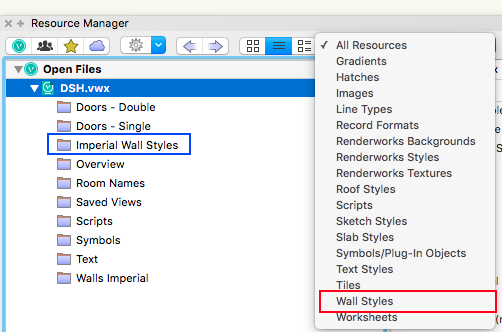
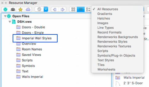
I have copied workspace and a file containing wall scripts that call wall styles to a remote machine. However, on remote machine when I open the copied file the wall scripts will only ever draw one of the styles contained in the copied file. If I compare the 2 Resource palettes the remote machine does not list the Wall Styles. Is there something really dumb I am missing - I thought the Styles would be contained in the copied file. The image on the right taken from local machine shows Wall Styles listed - see red box. But on remote machine listed in blue as per local machine but not under resources drop down menu. Any advice much appreciated. Michael
-
1. Where should i put things like Door/Window Styles in, when there are no Door/Window Style Folder types ? In Slab or Wall Style Folders ? 2. Can I rename "Standard Named" Folders to suit my own Naming Standards, rename these objects and move things around ? (Heliodon Symbols, Saved Views, and such ?) or will I risk things no more being found ? Or is that something that can be (fully solved) and needs to be solved by "Standard Naming" Options ?
-
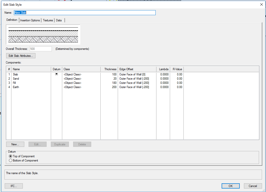
I have set up a slab style as shown in the below image. As you can see in the offsets have set the lower 3 to have a -200 offset so that I can draw conc blocks around perimeter. The style has worked fine for most applications. Have a growing need to the -200 offset to 3/4 sides with no offset to 1/4 side (Basically where the slab is adjacent an existing structure). Is there a trick to get the object to show offsets to selected sides only or is this a case of having to use a work around. Thank in advance.
.png.841ac4a4543f36be69911081589843a4.png)