DuncanR
-
Posts
29 -
Joined
-
Last visited
2 Followers

-
Anyone else having a problem with saving palette positions/sizes in 2024? Despite using 'Save Palette Positions' each time, I have had to resize all palettes on the left and right side whenever I start up VW2024. Also If I accidentally grab and drag the top bar into windowed mode vs full screen it makes the window tiny and again resizes all the palettes (at least only the first time it happens each session). Very frustrating - Is there something I'm missing or is this a bug? I don't remember having the same issue with earlier versions.
-
Data Visualization and Exterior/Interior Wall components (@ Windows)
DuncanR replied to DuncanR's topic in General Discussion
Realise this but i've created the data vis to highlight other information and will be using it on other projects where we have moved on from the inner/outer wall details so easier just to keep it on. -
Data Visualization and Exterior/Interior Wall components (@ Windows)
DuncanR replied to DuncanR's topic in General Discussion
If i do this on top of the Data Visualisation I can get them to show all a solid colour. Not ideal but it will do for now. Thanks Tom. -
Data Visualization and Exterior/Interior Wall components (@ Windows)
DuncanR replied to DuncanR's topic in General Discussion
I'll give this a shot and see if it will work -
Data Visualization and Exterior/Interior Wall components (@ Windows)
DuncanR replied to DuncanR's topic in General Discussion
Hi Matt - This is an existing project that is now nearing completion and we are preparing As Built information. Don't really want to go through all the window styles changing from the Ext/Int wall Detail to Wall closures, especially since there are ongoing issues with the wall closure, e.g. wall closure hidden when a sill is used. -
Data Visualization and Exterior/Interior Wall components (@ Windows)
DuncanR replied to DuncanR's topic in General Discussion
@Matt Panzer @Pat Stanford Any solutions for this come to mind? It is rearing its head again for another project i'm working on but can't for the life of me find a solution -
Help!! Wall closures just not working
DuncanR replied to hugobillington's question in Troubleshooting
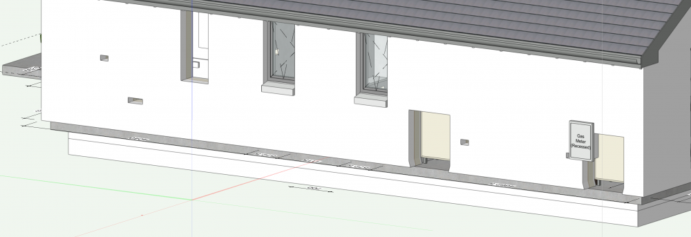
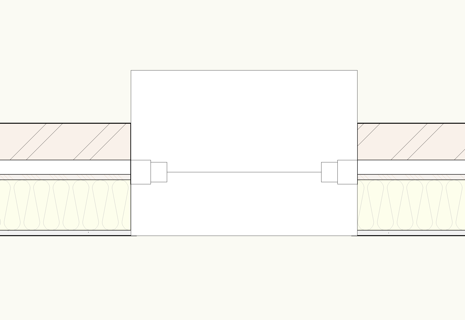
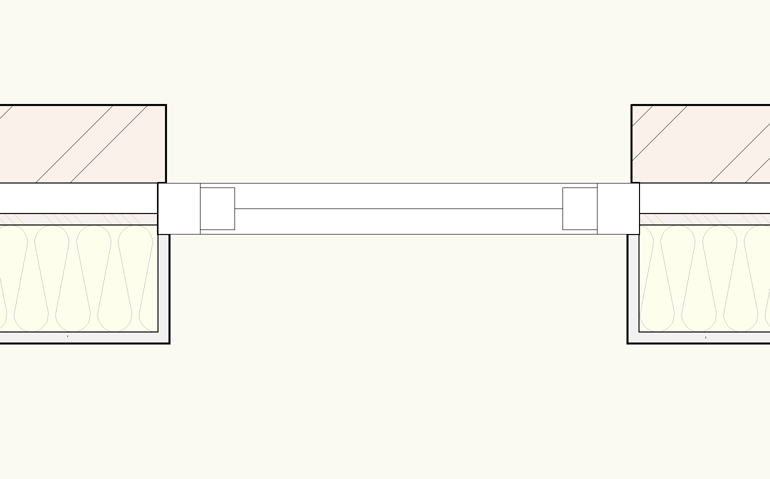
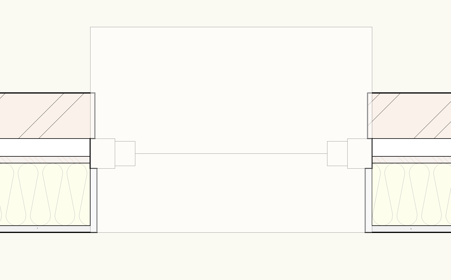
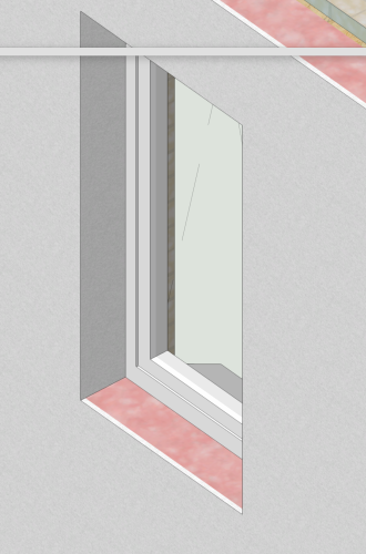
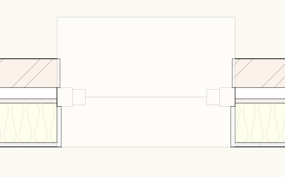
With SP3 released I was hopeful that the wall closure issues might all finally be resolved so we can put them into use. I have to say I have finally managed to get the component wraps at the closure to work for a window in both Top/Plan and 3D. ...until i introduced a sill. As you can see, with the opacity turned down the closure wraps are located behind the sill. I have tried adjusting the cut plane but it appears to have no effect. Neither does amending the draw order. Am i missing something from the multitude of options that can affect the wall closures or the window visibilities or is this the next bug to be solved with this function? I have used stock vectorworks wall style and window style from the library for testing this as a baseline, file attached. Wall Closure Issues.vwx Out of interest it would also be good to know why the sill colour fill projects all the way to the internal face of the wall no matter the sill settings (We'll leave the need to include an internal sill option for another day) Hopefully @JuanP or @Matt Panzer know what's up.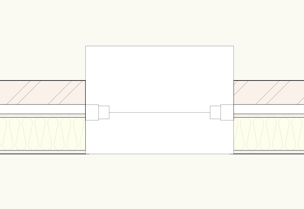

-
Twinmotion: How to redeem the promo code and install the software
DuncanR commented on Neil Barman's article in Installation
We expect to be replacing our office equipment over the next couple of years with the first machine being replaced in the coming months. This may involve changing from Mac to PC. Will there be any issues transferring the license from a Mac to a PC? -
Agreed, however i'm not aware of any way to do this currently. Maybe one of the pros will know @Matt Panzer?
-
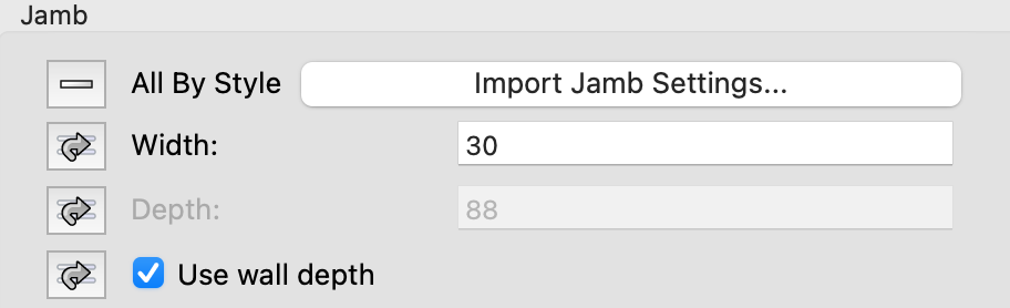
We do this by reporting jamb size for internal doors as we design for timber construction so we have it set to 'use wall depth' anyway You could do the same for external doors but we don't because it looks unrealistic on our GAs. Unsure how you would report the wall thickness if your jamb size differs i'm afraid.
-
Why does the fascia option only work on eaves and not gables?
DuncanR replied to MaltbyDesign's topic in Architecture
You could also do your fascias as an extrude along a path. That way you can have a standard library of profiles for use. We use this approach for almost all fascia/soffit arrangements as the built in tool just doesn't do what we want it to. -
Thanks Matt - Not an ideal solution - almost as well doing just a stand-alone annotation. With the every increasing number of elements that can be set/controlled via styles (data tags etc.) I'd think adding the ability to scale styled markers within the viewport advanced properties is something Vectorworks should look at including in a future release. Even tying them to one of the existing scaling options (markers or symbols) would be a step in the right direction.
-
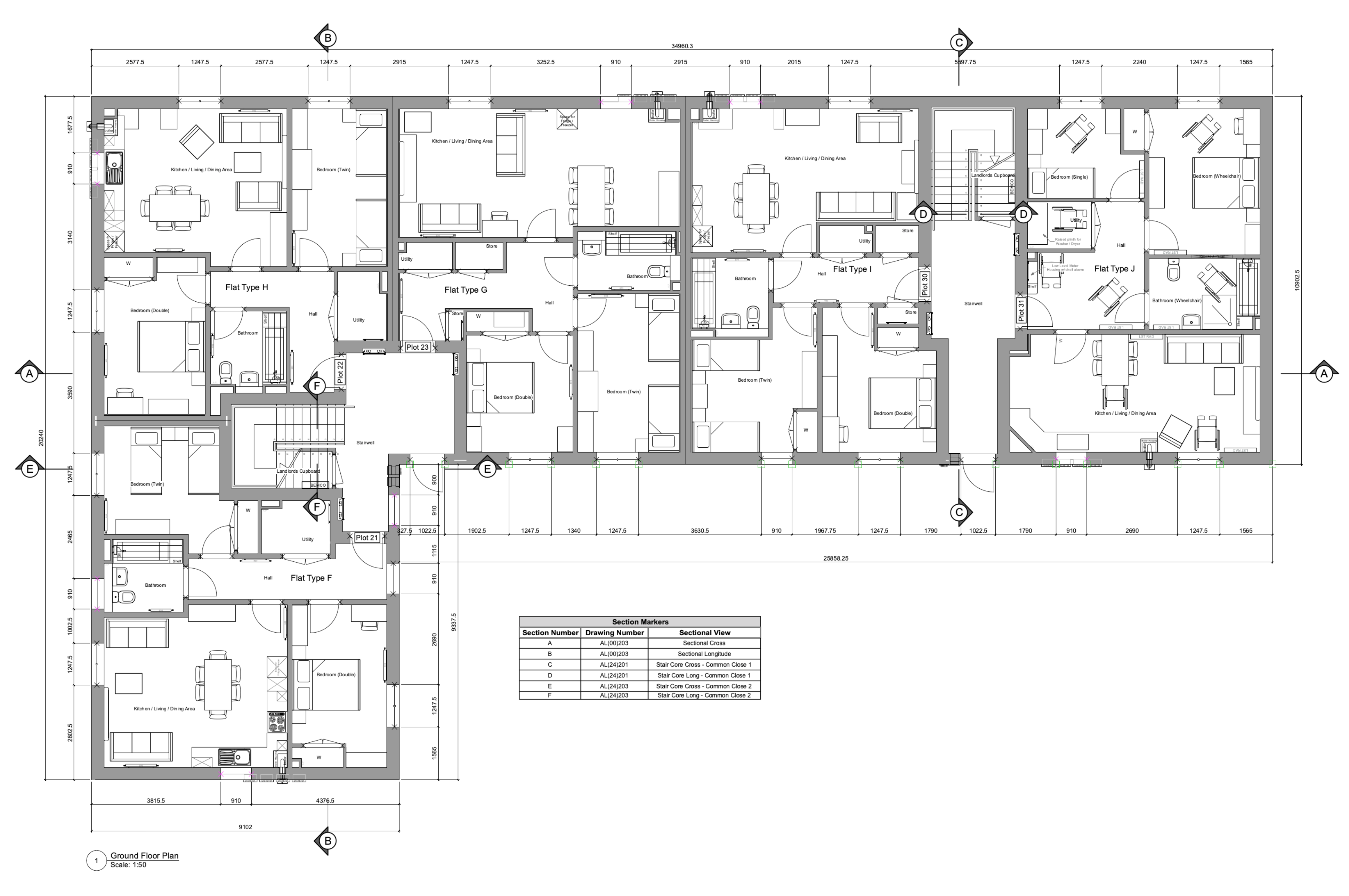
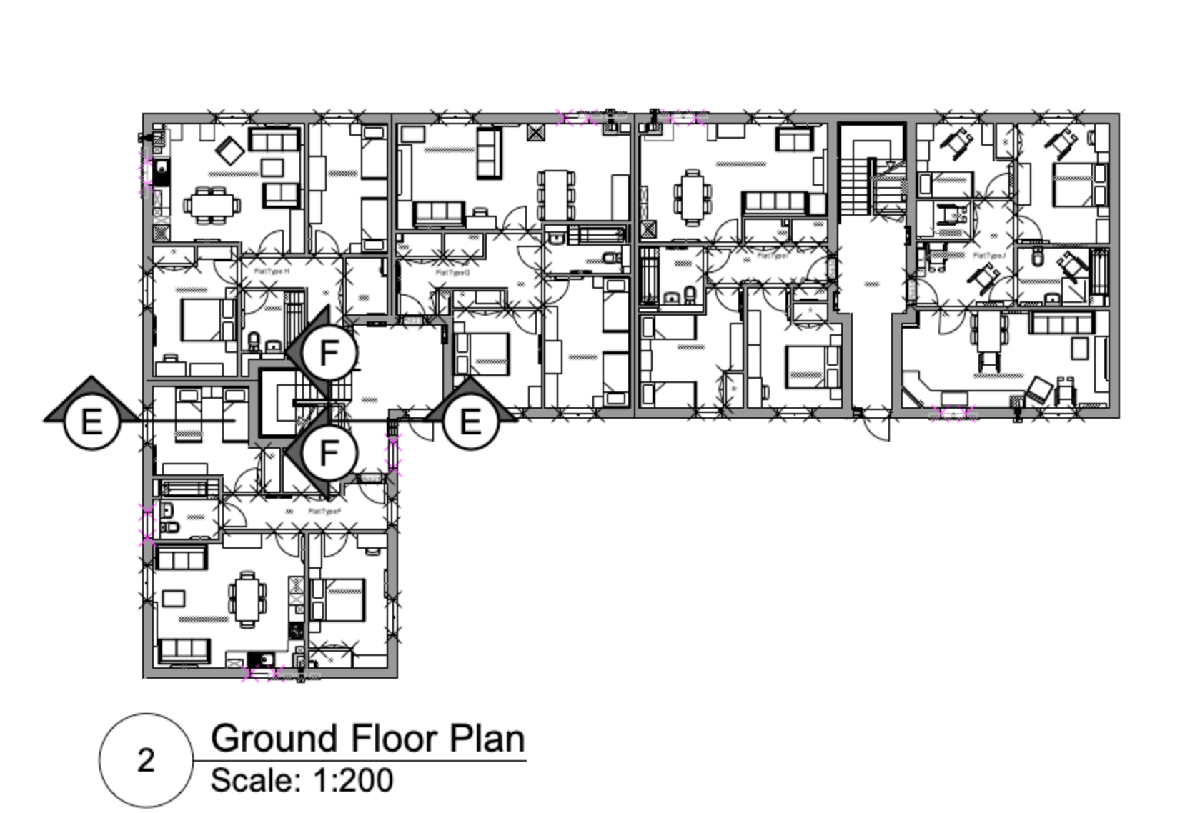
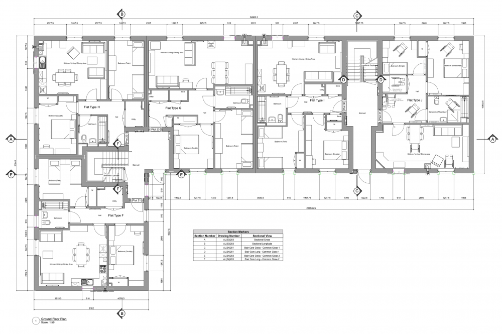
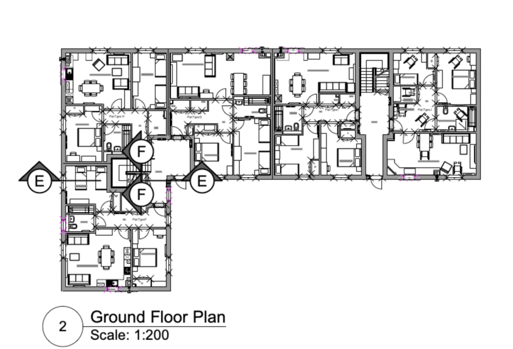
Hoping someone can help with this and we're not missing something obvious. When using coordinated section markers on a plan viewport (1:50) we also show these on the section sheet layer adjacent to the associated section viewport in a contextual plan viewport at a smaller scale (e.g. 1:200) - to allow those reading the drawing to easily identify where a section is taken if reading the section drawing in isolation. Our issue is that the scale of the section markers on the 1:200 scale context viewport appears to be a universal setting across all instances of the marker that are associated with that particular section viewport, meaning they show as either impractically large on the context plan (as shown below) or too small on the main plan if scaled to suit the context plan. Trying to scale markers/symbols etc. in the Advanced Properties for the viewport doesn't appear to affect them and if we change the scale factor for the marker in the annotation layer of one viewport it affects the markers in all other viewports. Is there a way to individually scale these markers for legibility? We are currently working off VW 2022 SP1.1 - While we are aware that SP2.1 is the latest version, there is a known issue with wall hole components of symbols attached to walls that is yet to be fixed.
-
Thanks for confirming Matt. Unfortunately, removing the symbols from the wall isn't an option as this affects every live project that we are working on..that's a LOT of sockets, furniture etc. Following a phone call to SS tech support we have reverted to SP 1.1 until the issue is fixed. Luckily CMD+M with a value of 0 for a single symbol in each wall or opening the roof edit dialog and closing with no action at SP1.1 seems to fix the issue on the 'corrupted' file.
-
Recently updated to SP2 and upon opening a project file to make some changes I've noticed that if i amend a wall, a symbol in a wall or an element connected to a wall (e.g. a roof) all 'symbols in walls' start showing a wall hole around the extents of the 3D symbol objects. Wall breaks are off and there are no wall hole components in any of the symbols. Even checked the new wall closure options to make sure they hadn't been activated as a default but they are also off in both symbol options and wall style settings. Undoing the change to an element reverts all items back to normal. Bug Report submitted but interested to see if anyone else has had this issue with SP2? Attached both the file prior to any changes made with SP2 and after roof edit dialog has been opened and closed with no change so it has affected all walls connected to it. Model Type 2 [Effected].vwx Model Type 2 [Uneffected].vwx