Search the Community
Showing results for tags 'spotlight'.
-
Hi I am trying to render a scene using custom lighting symbols and have the color of the output react to the viewport class color set. I have created some custom fixtures and have a lens in one separate class and the light source in another. When i change the color of the viewport classes to be different than the classes of the main file, only the lens class actually changes color in the render, and not the light sources. The sources are the same color as the main class color, and not the viewport class color. I have the light source in the 3D model set as style solid fill and color to class style. The lens has a texture with color set to "object attribute". Is there a setting somewhere that needs to be changed in order for the viewport class to set the of the light source? Or is there another problem?
-
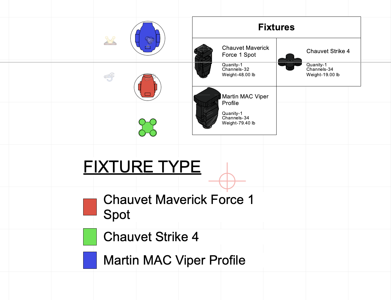
 Got my graphic legend working for doing fixture summaries, and that works great, pulls in Type, dmx channel count, weight etc. is there any way for the graphic of the fixture to render with the color of my data visulization? I usually color code fixtures on plots and would love for the key on the side to match. Currently just renders in the default texture it looks like. pic attached for example.
-
Helo, I did recently as follows: I created a show rig setup in Spotlight. Just fixtures in correct positions, some truss and flybars. Then I exported MVR to my GrandMA3 showfile and merged it into my file. Then I did the patch inside MA3 software, assigned correct GDTF libraries, adjusted Layering and Classing a bit and exported MVR from GMA3. I imported this adjusted MVR file into original *.vwx file. I hoped for updating information in already existing set-up, so already present fixtures get patch information, etc., but there just appeared new set of fixtures upon original ones, they all fell into one layer ignoring sorting made inside GMA and they do not have correct geometry. Is there some major wrongdoing on my side? Thanks.
-
Hi everyone, We are a company who does event plan for different supplier and event planner. We work most of the time with the same AV suppliers and we want to use the inventory and equipment list in our projects. Is there a way to build the equipment inventory of every supplier that we work with, and use them in multiple project we do? I tried some stuff but it seems that i need to rebuild the inventories list on every project to be able to give a source to the symbols or equipment. Hope it's clear enough.. Thanks a lot!
-
 Perhaps there is a way already, and I haven't learnt it yet, but in case this isn't a thing: It would be nifty to have the ability to set a user folder where I can store GDTF fixture files and VW automatically directs to that folder location, instead of importing fixtures each time. AND/OR if the resource manager could link directly to the GDTF Share and you could download the fixtures directly from the resource manager.
 -
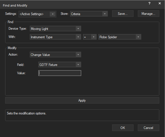
In VW2024 Update 1 it seems like you cannot use Find and Modify to change the value of GDTF Fixture. Is this how it is intended to be or am i doing it wrong? I was hoping the value box would allow me to go through the list of imported GDTF fixtures that are in the document. Attached is a screen shot as an example.
-
Version 3.0.0
1,363 downloads
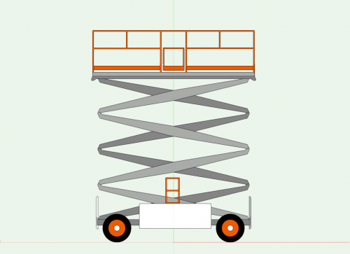
This Marionette object is a Scissor Lift PIO. You can place the Scissor Lift in your drawing and set the height via a Slider in the OIP. (See video.) All the different parts of the Lift are different symbols, and the Marionette script places each symbol at a particular insertion point and rotation based on the value of the Slider. If you wish to share the object, make sure that you share the entire symbol folder that holds all of its accompanying parts. This object was based on a symbol created by @barnes2000. Thanks Scott for letting me play! -
Hello All, Whenever I create seating sections there is no longer a seating count worksheet created. I can manually run a report, but it isn't formatted and doesn't include seating totals. Any ideas? I have searched all over the forum and cant find anything. Thanks, Capp
-
 With more and more fixture manufacturers making GDTF files available, I frequently have to import several of these when making a new drawing. The current workflow requires multiple steps to import through the File > Import menu, which is quite awkward to navigate since it currently contains 30 options. It would save time and be a lot more convenient if I could simply drag-and-drop onto the application window as can be done with PDF's. For extra credit, allow the user to re-order or hide items on the Import submenu so the more commonly used ones are easier to find. For extra extra credit, allow all valid file types to be imported via drag and drop.
 -
 After creating vectorworks schematic views, I have a question. Right now I left the image while uploading it, but the whole object seems to be rotating. I want my fixtures to look like they are in 3D, but I'm wondering how to do that. (In 2D state...)
-
Instrument Summary tool continues to be lagging heavily still on v2022 SP3. It's not tenable to wait upwards of 1-2min for VW to stop beach balling.. Can anyone relate? I'm running right now on a 14" MBP M1 Pro.
-
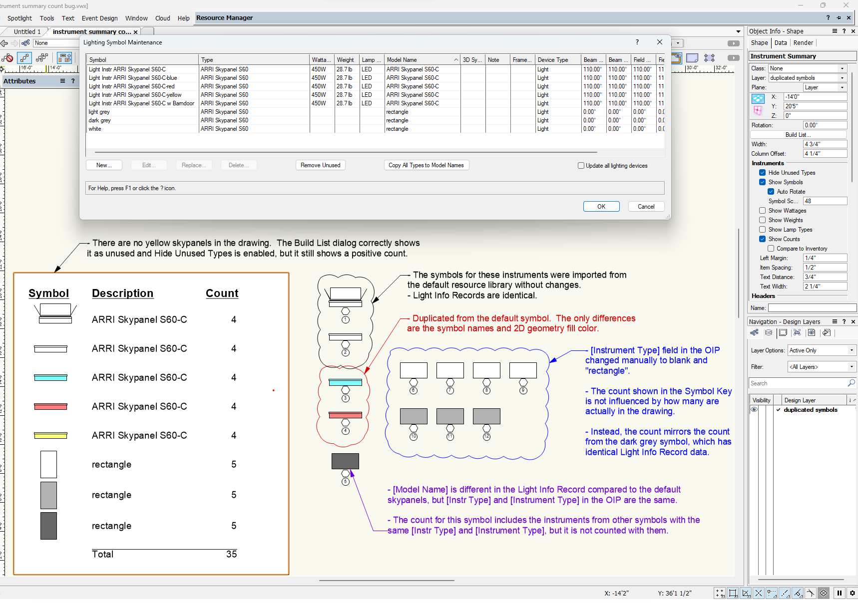
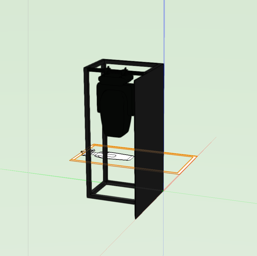
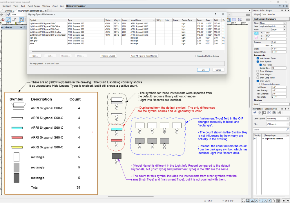
This is an active bug in Spotlight 2023 SP6, but I've seen it for a few years. The attached file and screenshot show what's happening, so I'll try to keep the post itself as short and to the point as I can. Synopsis The Instrument Summary Tool's Show Counts function gives false results when you have multiple lighting device symbols with certain identical data in the Light Info Record (LIR) and OIP. Specifically, the [Inst Type] and [Model Name] fields in the symbol LIR and the [Instrument Type] field in lighting device OIP's are involved. Description As seen in the screenshot, There are 12 instruments in the drawing, but the counts in the Instrument Summary are wrong. The Instrument Summary list is organized by symbol name, with each symbol having a separate line and its own count. The root issue appears to be that symbol name is not the top-most criterion used for counting. This means that instruments generated from different symbols can be counted together on the lines for each separate symbol, multiplying the true number. In the demo drawing, I have four instruments generated from four discrete symbols representing Arri Skypanel S60-C's. The two black and white symbols were imported directly from the resource library, then the red, blue, and yellow versions were created by duplicating the original symbol and changing the 2D geometry color. Because the relevant fields in the LIR's are identical, they all get counted under each symbol. Note in particular that the yellow symbol is not even present in the drawing, but still shows the count for the other four due to the bug. It's worth pointing out that anyone using the two black and white skypanel symbols taken from the VW resource library will encounter this bug without having made any customizations. There are other examples in the resource library of sets of symbols with identical LIR's which will cause this bug out of the box. I created the bottom three rectangle symbols in the Instrument Summary from simple 2D geometry which I turned into a symbol, attached the LIR and copied the [Inst Type] field from the skypanel symbols, then duplicated. I included the Lighting Symbol Maintenance dialog in the screenshot to show the LIR values of the various symbols. The counting bug takes on different behaviors depending on which of the data fields match and which don't, as noted in the screenshot. The bug variations for the rectangle symbol counts come from the [Instrument Type] in the OIPs being different from [Inst Type] in the LIRs, whereas they are the same for the skypanel symbols. For the dark grey rectangle devices, the OIP [Instrument Type] matches the skypanel device OIP's, and for the white and light grey rectangles it is different. Comments FWIW I have encountered this bug numerous times through sharing files and collaborating with other users on film set lighting plots. As a team, we frequently create customized variations of the resource manager lighting device symbols, most commonly to represent instruments which are not in the resource manager, or for different accessory buildouts. It is quite easy to duplicate a symbol, tweak the geometry or colors, then begin using it without updating the LIR fields, but it is rather tedious to make sure each symbol variation has unique data in the relevant places to avoid this bug. In my experience many Spotlight users aren't familiar with the finer points of using the Light Info Record in the first place and don't know how to update it. To my mind, the ideal solution would be to fix the count algorithm so it uses symbol name as the first distinguishing criterion, as that would remove the requirement to give each symbol unique data in the LIR and OIP. Thanks as always for all the work the mods and devs put in to keep VW humming. instrument summary count bug.vwx
-
It would be great to have the ability to change render mode for objects that are using their 3D symbol in the plan view. For example, when drawing lighting trusses that are raked out of level, the 3D symbol is used in plan view, but it is only able to be rendered in wireframe. I would like to be able to render the truss symbol in hidden line while in plan view, as it looks much cleaner. Currently if I change render mode it snaps into top view and the 2D Symbols for all the lighting instruments and lost. Setting background render to hidden line gets closer, but its not the look I'm after.
-
- 2
-

-
- hidden line
- plan view
- (and 2 more)
-
 SPOTLIGHT should have the "convert to wall" option available >>> the polygon and "solid addition" or "solid subtraction" we need to create in the world of Theatre ... but then use it as a wall for scenic and/or venue overlay to a show design. In creating Scenic Items and when drawing out a theatrical/event venue you are making your elements out of available tools. The ability converting them to a "WALL" is something that I would use almost daily... but can't afford the extra $1000 for the Designer workspace for just that ability. (and the Advanced Stair Tool as noted in another thread...) Thank you!
 -
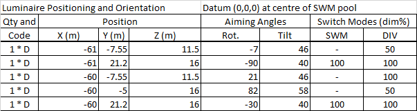
We get data from Calculux, in CSV format: The requirement is to automatically populate a drawing with lights. The 'Qty and Code' field is a reference to a key. For example, in this case 'D' could be any sort of light; a flood, a spotlight, a wash, made by any manufacturer. Assuming it is possible to associate the key to a lighting device in the Resource Manager, is it possible to insert a Lighting Device (as if one were using the Lighting Device Tool) programmatically? I'm looking at the documentation of 'VS:CreateLight' but it's not exactly exhaustive.
-
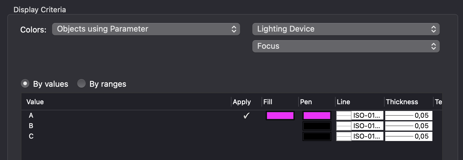
 Hi All, I want to get the older crew of the company to step away from their trusted and reliable 3rd party plug-in set and start using spotlight. The main thing I get back as to why they are reluctant to switch is the fact that they can't easily color code Focus Point sets of fixtures. Case: For a TV broadcast there are multiple people around a table that need to be light. In the rig there are numerous amount of conventional fixtures all with their own dedicated purpose. Example: Focus Point A = Presenter = Red Focus Point B = Table Guest = Blue Focus Point C = Guest 1 = Green Focus Point D = Guest 2 = Cyan Focus Point E = Guest 3 = Orange It's easy to color the whole fixture but that also clutters the drawing as the rigs are very crowded most of the time. The 3rd party plug-In only changes the color of the barn-doors or lens-barrel, talking just conventionals. I don't mind editing large amounts of fixtures with a simple piece of geometry inside, assign to a class. But I can't seem to get that working with Data Visualization. There is a way to edit the color via attributes and the spotlight preferences menu, but that is not the way I believe. I've put that option to Modify lighting device color [v] -> Object attributes -> Modify Only Geometry in the Class: "Focus Point Color" I've just took a standard ETC Lustr2 Zoom 25-50 symbol, drawn a poliline over the barrel outline and assigned it to class: "Focus Point Color" I've tried the object criteria in Data Visualisation but no results Display Criteria are set as follows: Please help!
-
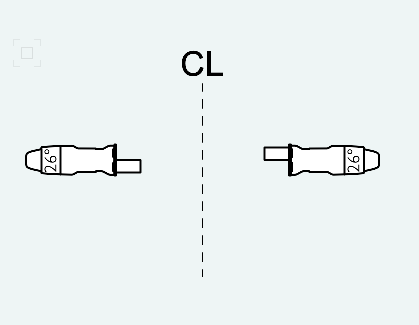
I often mirror boom units from one side to the other and am frustrated by the way that half top-hat accessories mirror across - flipping the accessory vertically (image attached) I currently use two versions of this accessory for SR and SL but am looking for a cleaner solution. Can anyone offer an explanation or a solution to this? Many thanks!
-
When I create a floor with an 3d Polygon applied with a texture the beams of my fixtures are going thru the floor/walls when Iam in shaded mode. In Fast renderworks or quality renderworks the beams will be stopped by the floor/walls. In my textures I have checked cast/recieve shadows. Iam using a JB Lighting fixture in my test drawing but it happens with all fixtures. MacBook Pro 16" M1 macOS Monterey 12.6.3 Vectorworks 2023 SP3 Kind Regards, Erik-Jan Berendsen
-
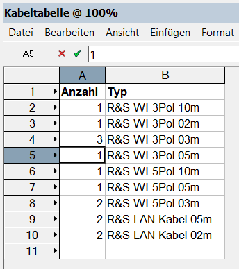
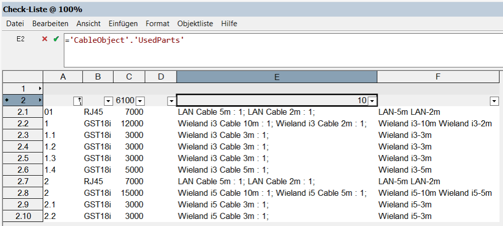
I've created cables with Cable tools and I want to extract the types of the cables, the length and the id to which is assigned. Spotlight can already a list of the cables and the number of these but without the cable id. I can extract the data into a table from CableObject but the list is concatenated. How can i create the first table with the cable ID from the second table? Spotlight can extract already data which is created with the "CablePart". And this is in some away confusing. I'm thinking that i must write a script or create a Marionette. Can you help me or point the right direction? Thank you! Bogdan
-
 I am seeing something weird, and I don't think it's just me or the custom symbols I am using. If I add a TV object using the default Spotlight tool, the TV object is placed with a Z height (even when dropped from plan view). The Z height seems to be improperly looking at the "Height" screen parameter stored in the TV screen data in the symbol. This is something new happening for 2023 after moving resource files over. This is also happening when inserting the stock symbols as well, so I would not think that there has been a change to the tool and what the fields mean/do. Anyone else run in to this? It's minor, just having to correct the Z height, but it's bugging me.
 -
 It would be amazing if the Focus field could drop down and you could choose from Focus points that you have put in your drawing. Please and thank you!
-
 I need to be able to have a Schematic View of a vertical lighting pipe on my design layer next to my original lighting position instance, but if I select Show Beam, it turns it on from both the original instance, and the Schematic View. Can I turn it off in just the Schematic View?
 -
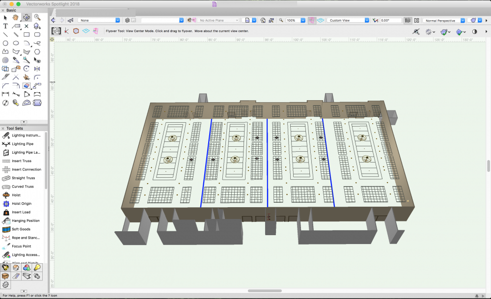
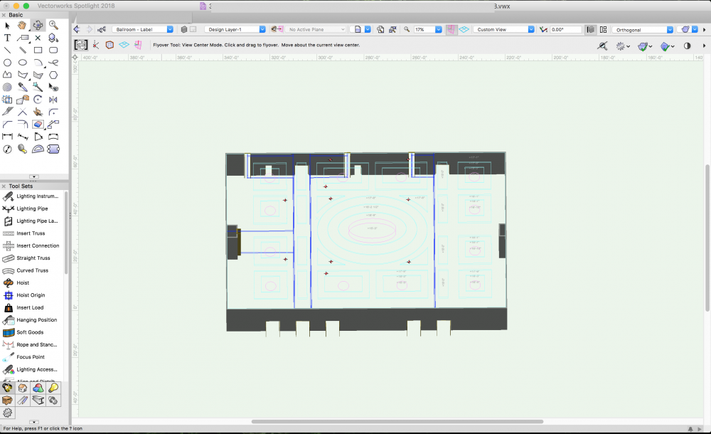
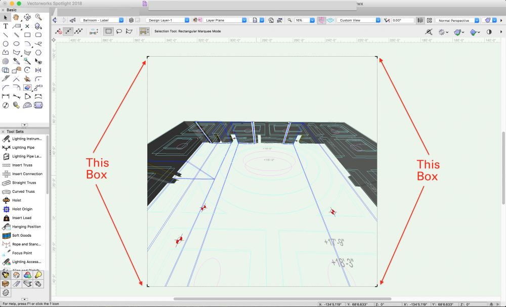
Hi all, Received a file to work on and when going into 3D view I now get this resizable box that only shows the model within said box, it does not appear in any of my other files. The "viewing box", as I am calling it, goes away when I enter Orthogonal view but I need to work in Normal Perspective for this. Attached are pictures of the "viewing box" on the new file in Normal Perspective, No "Viewing Box" on the same file in Orthogonal and a shot of another file that I checked in Normal Perspective that does not have the box. Any hep would be appreciated.. even pointing me in the direction of what this box is called so I can track down some settings would help. Thanks!
-
Why does SL Auto Numbering seem so uh iffy? AutoNumbering seems to fail regularly with multicell fixture numbering. I have attached a video demonstrating both the SL AutoNumber fail as well as the current workaround— Savvy Sequencer, developed by @JBenghiat. Screen Recording 2022-08-31 at 6.54.40 AM.mov
-
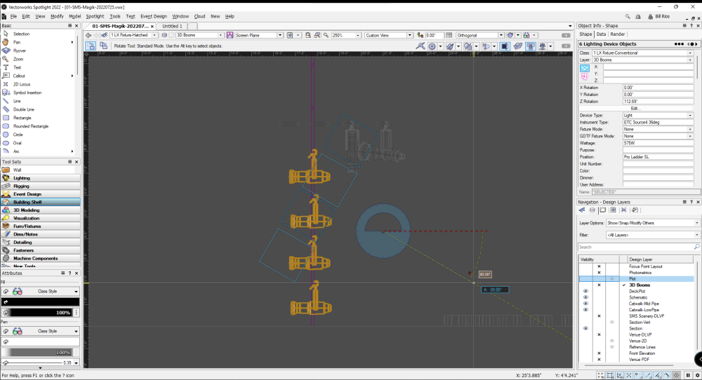
Rotate Lighting Device Mode not activating as expected
Bill_Rios posted a question in Troubleshooting
Having an issue with the Lighting Device Rotate Mode. When selecting only lighting devices on a vertical position, I expect them to rotate from their insertion point/c-clamp. That is not happening. They are rotating off of the center betwen the selected lighting devices. I expect it to behave like this video: I did a test in a blank file with a fixture from VW library and it worked as expected. I imported the geometry and devices into the file i'm working on and the rotate lighting device mode didn't work anymore. I run a custom workspace so I switched to Spotlight Standard and had the same result. There is no mode to switch to in the tool bar. Do I have a setting turned off in this file? Running SP4.