


CipesDesign
-
Posts
5,153 -
Joined
-
Last visited
Content Type
Profiles
Forums
Events
Articles
Marionette
Store
Everything posted by CipesDesign
-
If you are using a Site Model (derived from your Polys), and Site Modifiers are not showing up, make sure that "Show Proposed" (or Existing and Proposed) is selected, both in 2d and 3d. Then make sure to update the Site Model.
-
Can a roof opening be edited or deleted??
CipesDesign replied to Sinead V's topic in General Discussion
Without seeing your file (or a screenshot of the roof plan) it's hard to be sure. But I usually use more than one Roof, or Roof Faces for this type of thing. Another trick is to Ungroup the Roof, which will yield a number of Roof Faces. I find it much easier to edit and play with Roof Faces; you can Add/Clip Surface, etc. and you can duplicate one roof face and then rotate, edit, etc. -
Also, in regard to the original post, a really great (fairly recent) enhancement: hold the "b" key while hovering over the drawing to reveal, pre-select and select hidden/covered objects!
-
SIDEBAR: Some years ago I attended an expensive 3 day training course (at that time only third party providers were doing that). I went in thinking I knew a lot about the software and how to use it. Boy was I surprised. Best money I've ever spent! [Thank you Janis K ;-)]. Just saying...
-
Best Practices for Contour Labeling on a Grading Plan
CipesDesign replied to Alex G.'s topic in Site Design
nca777, keep submitting bugs and enhancement requests. Be persistent, constructive and patient. -
Best Practices for Contour Labeling on a Grading Plan
CipesDesign replied to Alex G.'s topic in Site Design
The plan I attached was a preliminary version, mainly used to demonstrate graphic capabilities (not grading capabilities). I agree that the Site Modeling tools could be more refined. This takes time; software evolution is slow. If you have not done so yet, you might consider filing specific bugs and/or enhancement requests which clearly state flaws and/or possible improvements. -
If you examine a Wall in 3d by Double Clicking, or by selecting the Reshape Tool, you will notice that in it's basic form there are six little nodes (vertices); one at each corner and one each at midspan along the top and bottom of the Wall. These define the Wall. One way to think of these is that they are almost exactly like the "handles" on a 2d rectangle (or polygon); but these are in 3d. If you create a basic Wall, then double click, you will also see that new options become available in the Mode Bar (by the way, all of this stuff is in VW's Help!). The first is Reshape. Try grabbing one of the corner vertices and pull it up or down; watch what happens! The second is "+", you can use it to create a new Vertex by clicking on an existing Vertex and pulling the new Vertex in the desired direction. The third is "-" which is used to delete a vertex (note: some vertices cannot be deleted as they are integral/required for the form of the Object). I recommend that you open a new file and play with these functions. I think you'll quickly get the idea. P
-
Best Practices for Contour Labeling on a Grading Plan
CipesDesign replied to Alex G.'s topic in Site Design
A couple followup comments: 1) You can set the graphic attributes for Proposed and Existing Contours in the Site Model Settings/Graphic Properties. 2) If the current "grading" tools are used as intended, there will be very clear "limits" to the altered (graded) area(s), and Proposed Contours will tie in as expected. 3) It does take a substantial amount of time to master these tools; but it's well worth it in my view. 4) Don't forget to set the Site Model to "Show Existing and Proposed" in 2d; "Show Proposed" in 3d; and don't forget to Update the Site Model with each change. As proof, see attached, which was produced using these exact methods. Site_Model_Example.pdf -
One way is to use a Wall, set to 6ft High and about 2" thick, and textured with Wood Decking (turned vertically it looks just like fence boards). Draw the wall in Top Plan, on the Site Model Layer, then use the Send to Surface command. Once done, you will need to add some top vertices and adjust their elevation accordingly. Post back with further questions if needed.
-
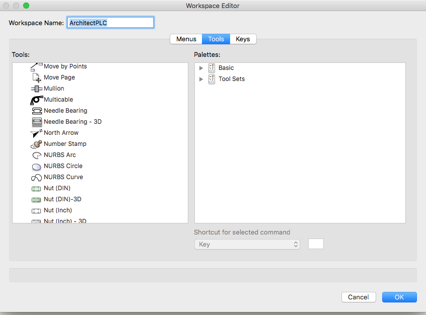
Not crazy at all. I use the Number Stamp on every drawing I do! P
-
It is called the "Number Stamp". You can add it to your Workspace via the Workspace Editor (Menu=Tools>Workspaces>Edit Current Workspace). Click Tools in the center pane, then All Tools in the left. Tools are listed alphabetically. See attached.
-
In my view, Extrude Along Path (EAP) is the way to go.
-
This is difficult task in VW's. Probably more difficult than in real life (with a D9). I would start by creating Pads with Boundaries in the Site Model. Then for modeling and visualization I would overly the whole paved portion with a Texture Bed. The most difficult part is accurately connecting the Pads where they intersect. Pads can now have two slope directions, which helps some. But unfortunately I don't believe we yet have the ability to create curved/cambered surfaces with Site Modifiers. Ultimately you need to think in terms of 3d triangles (which is what the Site Model is made of). You might also use 3d Polys and/or Nurbs Surfaces, and then use those as Modifiers. I would suggest creating this in more than one part, using as few parts as possible to get the desired result. Please post back with further questions and results!
- 2 replies
-
- 1
-

-
- site modifiers
- site mesh
- (and 1 more)
-
Could it be that Insertion Mode is not on??
-
So keep in mind that the surveys many of are working from to create Site Models are already (sometimes heavily) interpolated; that is, the surveyor walked the site and took a series of readings, not necessarily in any particular or strict grid pattern. Those "points" are then used by the survey software to interpolate the contours. So if you are creating a Site Model from contours, it will end up being double interpolated, so to speak.Three comments: a survey is only as good ad the person doing it; and often I ask for the survey "point file" and use those to create a Site Model ( and to check on the accuracy or frequency of the points); also, in every case (so far) the surveys and Site Models are more than accurate enough for what we do, and I don't usually fret about small (less than 1 ft) oddities. A lot of that will be worked out on site by the builder.
-
I would recommend using a discreet Design Layer for each major part of each structure, and I would build (model) it all on one Site Model. For example, House ML; House Roof; Shed ML; Shed Roof. You can set the Z (elevation) to whatever you want in any Design Layer. Not reason two layers can't have the same Z. Using separate layers will be very useful later when you want to create plans, elevation, sections, etc...
-
Make sure that Unified View is ON.
-
Placing a multi-level house on a DTM - best practice?
CipesDesign replied to skavan's topic in Architecture
Hi Gester, Yes, I usually use real world elevations (and in general I feel strongly that things in the virtual world should be as close to anatomically correct as possible). But sometimes you can run into problems if objects are too far away from the VW's origin (most recently I had a file in which Trees/Image Props would disappear in Open GL because the house was at over 2,500 ft above sea level). The reason I like real numbers is that I never make a mistake in the notes, etc., and the surveyor can locate stakes without doing any math. The other option is to use numbers under 100 when you building the Site Model, so 3,223 would become 23, and so on. If you do this you will not have "far from (Z) origin" issues, but you will need to remember the real numbers to convey to the people on site. As a side note, I had never had a problem with the Z origin until very recently, but have had many many problems being too far away from X and/or Y. -
One issue here is that VW's automatically assigns Z value to each subsequent Design Layer based on the delta Z of the previously created layer. I have never found that to be useful, and generally prefer to create all design layers with Z=0, then adjust in the Layer Setup as desired.
-
I would create a "dummy" shape (extrude) drawn (or placed) perpendicular to each wall you wish to trim. Put the shape(s) on their own layer and use that as the Fit to layer.
-
Creative workarounds to sometimes limiting parametric tools?
CipesDesign replied to chase@zebra's topic in Architecture
Unfortunately Wall Features cannot extend to or around corners (which for me makes them practically useless). Foe the situation you illustrate above, you can use a simple Extrude, but of course you will need to pre-cut it around windows and other openings. -
I use human models a lot. I do not recommend the Human Figure tool. It's stinky on many levels. If you want good results and are willing to spend a little money, try these: https://renderpeople.com/?utm_source=google&utm_medium=cpc&utm_term=USA-product&utm_campaign=kauf&gclid=CJa9oZrbydICFYpcfgod7i4BKA I have used them for years with no issues. They also offer a couple feee samples: https://renderpeople.com/free-3d-model/ Disclaimer: I am not associated with that company, I just use their products.
-
In terms of construction, I agree about a single tall wall (and most engineers will insist on that to avoid unwanted hinge joints). I would need to see the design in full to form an opinion. There are instances, like at a stairway, where the taller open space is pretty limited and where it might be okay to use a stacked system. However in terms of VW's, using one taller wall creates problems (challenge to display the wall on various plan levels, and the fact that you can't join walls on different Layers, for example). So I would use two stacked walls, with a portion of a floor in between (you clip out the stairway, or "open" area). Then I would describe the single tall wall in Section, and details if needed.
-
You could use an "opening" set to "clerestory" which will give you a dashed (dotted?) line. I would also make a very clear note in more than one place, and probably create a special framing elevation. Because in standard stacked framing the plates will be discontinuous this will be something your structural engineer will want to look at.
-
You need to cut a hole in wall above. You can use a window, set to "opening".