Matt Panzer
-
Posts
3,328 -
Joined
-
Last visited
Content Type
Profiles
Forums
Events
Articles
Marionette
Store
Everything posted by Matt Panzer
-

Camera Match and size of background Picture
Matt Panzer replied to PESSIN's topic in General Discussion
You're welcome! -
Camera Match and size of background Picture
Matt Panzer replied to PESSIN's topic in General Discussion
You're very welcome for the help, Maria! I'm glad you can now make good use of Camera Match! :-) Regarding the alert message. This is normal and happens when you change the size of the width or height of the photo image in the Camera Match object. When you first set the view and no crop (cut out) is present in the viewport, Camera Match will place one at the same size as the photo image. If you change the photo image, this dialog appears and allows you to keep the original crop or reset it to the new photo size. Clicking the right button will reset it to match the photo size. However, if you placed your own crop (to make the photo smaller, different shape, etc.), then you might want to click the left button to keep the custom crop. -Matt -
Camera Match and size of background Picture
Matt Panzer replied to PESSIN's topic in General Discussion
Maria, I just got a hold of the French version plug-in and it does appear that the two 48" defaults shown on my video turned into 48\q. You could try changing them back to 48", or use 1m as I suggested. Doing this will fix the defaults for new files or files that have never had Camera Match Reference objects placed in them. NOTE: While this should fix the problem, reinstalling Vectorworks or installing an update will reset these defaults. Of course, if you install an update that has these defaults corrected, then you have nothing to worry about. :-) I hope this helps for now! -
Camera Match and size of background Picture
Matt Panzer replied to PESSIN's topic in General Discussion
You're welcome! Actually, I originally thought it may be a template issue, but it would be best to first check the defaults for the Camera Match Reference plug-in object. Since I do not have a French version on hand, I'm attaching a video of how to check and set these defaults. If you're willing to try this, follow the steps in the video and tell me what the default values are for the following parameters: ControlPoint1X: This value should not be zero. If it is, try changing it to something reasonable (eg: 1m) ControlPoint1Y: This value should be zero ControlPoint2X: This value should be zero ControlPoint2Y: This value should not be zero. If it is, try changing it to something reasonable (eg: 1m) If all four of the above defaults were zero and you corrected them, try creating a new document and inserting new Reference objects. If you see the red and green axes in Top/Plan view, then the problem should not happen any longer. However, if the defaults already look correct, then I suspect it's an issue with the template file. ScreenFlow.mp4 -
Camera Match and size of background Picture
Matt Panzer replied to PESSIN's topic in General Discussion
Thanks for the information, Maria. I will get a hold of the french version template files to see if I can recreate the problem. I'll keep you posted... Thanks, Matt -
Camera Match and size of background Picture
Matt Panzer replied to PESSIN's topic in General Discussion
You're welcome for the help, Maria. Thank you for the information on how you recreated the problem in a new file. I have a few questions: Judging from the class names in the document, I assume you're using a localized (non-US) version of Vectorworks? If so, what region and language? Did you create this in a new "blank" file or from a template? If you used a template, can you tell me which template you used? Was it a stock template, or one you cerated? Thanks, Matt -
Camera Match and size of background Picture
Matt Panzer replied to PESSIN's topic in General Discussion
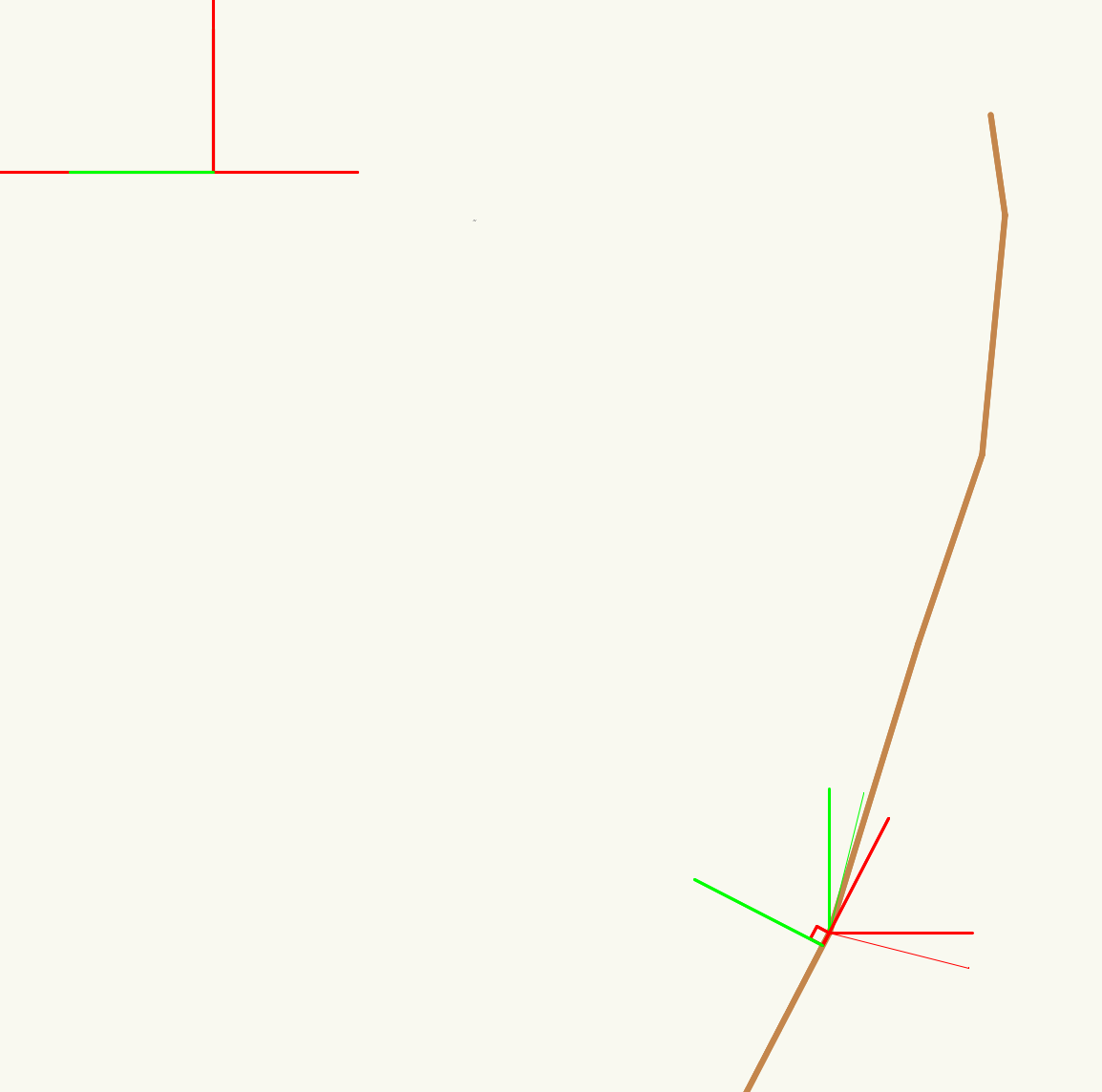
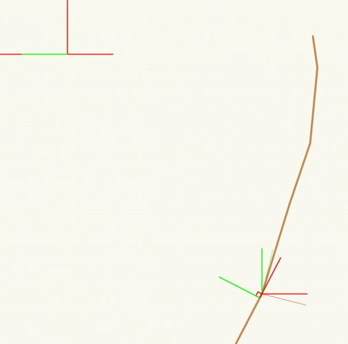
Hi Maria, Ok, thanks. It turns out not to be an issue with the photo image or Camera Match object. I looked closer at your file and wondered why the Reference objects had no left and right vanishing point controls (green and red lines) in Top/Plan view. I tried place a new one and got the same result. Somehow the defaults for the Reference object got changed so that these controls were zero distance from the Camera Match Reference point. Not only did this make it hard to find these objects, it also caused them to lose the left and right vanishing point directions. I fixed this in your file. You will now see these objects easier in Top/Plan and newly placed Reference objects should behave correctly. Here's a screenshot of the reference objects in your original file (they show is 3D loci): Here's one of the corrected file (notice the green and red lines): You should be able to selected and delete the References you no longer need and the Camera Match object should work again. Baumann_PRO_v1_v2018-Fixed.vwx The only thing I cannot explain is how this file got to this state. If you have other files with this issue, send them to me privately and I'll fix them. Best regards, Matt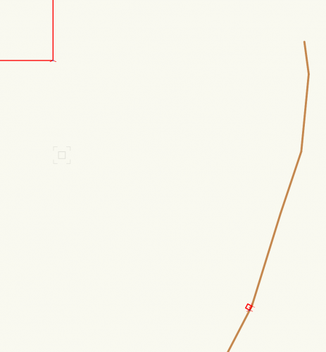
-
Great to hear, Sergio! I’m glad to help! -Matt
-
Camera Match and size of background Picture
Matt Panzer replied to PESSIN's topic in General Discussion
Hi Pessin, I took a look at your file and need to look into it a little further. Could you send me the original photo image file you imported? Also, can you tell me what import options you chose when importing it? Thanks, Matt -
Sergio, Good to hear you managed to get something close to what you were after. Obviously, we cannot expect users to redesign their doors like this just to get a muntin to line up. :-) Another way to deal with this would be to create a symbol of the door object and model the muntin as a separate object. If you'd like to keep it as a Door plug-in object for scheduling, you can use the symbol's geometry within the Door object. This is how I would do this. I'm including a lot of details so this looks more complicated than it is: Place the your door in the wall with the desired settings. For now, leave the transom muntin on. Select the Door and use the "Create Symbol" command in the Modify menu (use the "Leave Instance in Place" option). You should now have a new symbol in the Resource Browser and the door plug-in in the wall should now be an instance of the symbol. If you prefer to have the door in the wall as a Door object (not a symbol), select it and use the command "Convert to Group" under the Modify/Convert menu. FYI: The reason you may want to keep it a Door object would be for scheduling and IDs. The instance in the wall should now be a Door object. This object no longer has any connection to the symbol. Edit the Door object's Settings, go to the Genteel tab, select the "Use Symbol Geometry" checkbox, and select the symbol you created in step #2. Click OK. The Door object is now using the geometry from the symbol. Now we'll need to edit the symbol to suit our needs. In the Resource Manager, right-click on the symbol and choose Edit 3D Component. You can now select and edit the Door object within the symbol. From here, you could turn off the transom muntin in the door and model your own from scratch, or you could start from the muntin the Door already created. Because I'm lazy, I would choose the second option. While still in Edit Symbol mode, select the Door, Copy, Paste in Place, and Ungroup. You should no have a collection of objects selected. From here, I usually Group them to keep them all together. With the group I just created, now "Edit Group", select the muntin object (an extrude), Copy, exit the group, delete the group, Paste In Place and you will have the muntin extrude in place. Edit the Door's settings and turn off the transom muntins. Double-click on the muntin extrude to edit it's source polygon, reshape it as needed to get the vertical bar aligned, then exit the extrude. Exit the Symbol and you're done. I hope this helps more than it confuses. :-)
-
Hi Sergio, This setting is for setting the offset for the Prairie Style muntins only. Unfortunately, there is no setting to offset the Colonial muntins as you describe.
-
VW2017 - Highlighting Issue
Matt Panzer replied to Kevin McAllister's topic in Wishes Granted / Issues Resolved
No need to report it again. I found a few reports already. I agree that this needs to be fixed. I nudged the report to see if it can be dealt with soon. -
VW2017 - Highlighting Issue
Matt Panzer replied to Kevin McAllister's topic in Wishes Granted / Issues Resolved
@Kevin McAllister, Do you have the bug number on this? -
Sou you can select the Camera Match object in the viewport's annotations and see the parameters in the Object Info palette (but cannot edit them)? Does Camera Match work correctly in other files? I tested the cursor issue on OS X 10.11.6 with VW 2017 SP4. If you're on the same version, I'm not sure what the cause would be. Try changing the Navigation Graphics setting (in the Display tab of the Vectorworks Preferences dialog) to see if that helps.
-
How do we change decimal precision display of Slab Drainage slope figures?
Matt Panzer replied to Christiaan's question in Troubleshooting
LOL! No problem. :-) -
How do we change decimal precision display of Slab Drainage slope figures?
Matt Panzer replied to Christiaan's question in Troubleshooting
Enter the Edit Slab Drainage mode for the slab and click on the Slab Drainage Settings button in the mode bar. You will see a Display Precision popup near the bottom of the dialog. -
I thought the volume on all Marshall amps go to 11. Maybe a modeling error? :-) Good to her you fixed the problem! PS: I'm curious which spell did the trick for you.
-
I downloaded the file and here's what I see: 1. I cannot reproduce the cursor disappearing issue. 2. I do not see a Camera Match object in the viewport's annotation space. The mask object requires the Camera Match object in order to understand what background image to use for the masking. Could you have accidentally deleted the Camera Match object?
-
Can you attach a small Vectorworks file for us to look at?
-
Also, if you have rendered viewports in the document with the document preference "Save Viewport Cache" on, try turning it off, save the file, and check the file size. This will require you to re-render the viewports every time you open the file, but it will reduce file size.
-
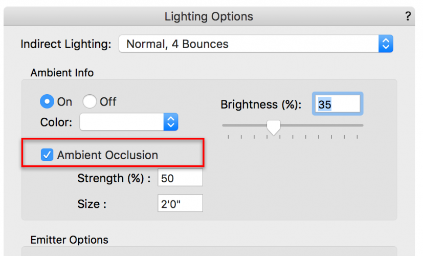
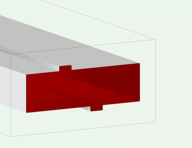
Try going to "Set Lighting Options" in the View menu and turn on Ambient Occlusion: A side effect of this feature is that the clip cube cut fill turns translucent:
-
Thanks for the file, Sky. Vectorworks 2018 fixed many issues similar to this so I’m surprised this is happening in that version. I submitted a bug with the file. One workaround I can think of would be to break the main roof up into separate roof objects by making the gable and Dutch gable with separate roof objects. I realize this is not ideal. Another option would be to create the dormer “manually” by placing separate walls with the window and a roof for the dormer. Then manually cut the hole in the main roof by placing a polygon in Top/Plan View and using the Subtract Surface command.
-
Could you attach a small Vectorworks file showing the issue?
-
Hi Sky, What version of Vectorworks are you using?
-
As Pat mentioned, Hybrid objects cannot be rotated off the ground plane. They can only be rotated around the Z axis. If that's all you need, one of these scripts should do it for you. This script will rotate selected objects about their centers (center of their bounding box): PROCEDURE MAIN; FUNCTION RotateIt(h :HANDLE) :BOOLEAN; VAR x, y, ang :REAL; BEGIN HCenter( h, x, y ); ang := Random * 360; HRotate( h, x, y, ang ); END; BEGIN ForEachObjectInLayer(RotateIt, 2, 0, 4); END; RUN(MAIN); This script will rotate selected symbols and plug-in objects about their insertion point: PROCEDURE MAIN; FUNCTION RotateIt(h :HANDLE) :BOOLEAN; VAR x, y, ang :REAL; BEGIN GetSymLoc( h, x, y ); ang := Random * 360; HRotate( h, x, y, ang ); END; BEGIN ForEachObjectInLayer(RotateIt, 2, 0, 4); END; RUN(MAIN);