Matt Panzer
-
Posts
3,337 -
Joined
-
Last visited
Content Type
Profiles
Forums
Events
Articles
Marionette
Store
Everything posted by Matt Panzer
-
Thank for you reply, Sam. I've always felt slabs had something to do with this problem, but was never able to reproduce it. Now that I know editing slabs seems to trigger it for you, I will concentrate on that to try to reproduce it. Thanks again, Matt
-
Also, Would it be possible to send me another copy of the project file with the wall joins in tact?
-
@Sam stork, Do you recall what types of actions you were doing in the file between submits (eg: editing walls, wall styles, slabs, dimensions, etc)?
-

Best way to cast shadows in section viewports
Matt Panzer replied to Phileas's topic in Architecture
@TomKen, Ah! Thank you! I don't think this was always possible. Great to know it is now! 🙂 -
Best way to cast shadows in section viewports
Matt Panzer replied to Phileas's topic in Architecture
Yes. This is what I've typically done as well for elevation views. Also, simple directional lights can be controlled per viewport via the Visualization palette, so no need for classing. Heliodons, however, cannot be controlled in this way. -
No problem! Yeah. The higher smoothing is far easier than the alternative. 🙂
-
You might get cleaner results by editing your line render settings for the viewport and raising the Smoothing Angle. I often set it somewhere between 30º and 70º. If you have not tried this, I'd try it first. I'm afraid the only other workaround would be to try to place planar objects (for the "Front" graphics) in the 3D component of the symbol and use classing to turn the visibilities of them and the 3D geometry as needed. This would basically mimic the VW 2019 behavior, but with a lot of additional work. I would not recommend this approach.
-
PDF changing the insulation tool pattern to zig-zags (not loops)
Matt Panzer replied to turnerhoskins's question in Troubleshooting
Have you tried a Resolution higher than 300? The lower it is, the more faceting you'll get. While 300 dpi should be plenty, I'm just curious if a higher setting makes a difference. Also, what scale is the viewport? -
This can be done in Vectorworks 2019: https://www.vectorworks.net/training/2019/getting-started-guides/bim-architectural/2d-components-for-hybrid-objects
-
Best way to cast shadows in section viewports
Matt Panzer replied to Phileas's topic in Architecture
Use OpenGL for the background Render Mode and Hidden Line for the Foreground in one viewport. Make sure to turn off "Show Edges" in the OpenGL Background Render settings so they don't muddy Hidden Line linework. Also, to get lighter shadows, experiment with the Emitter Brightness and the Ambient Brightness settings (in the Lighting Options dialog) to get the amount of lightness and contrast in the models and shadows. -
PDF changing the insulation tool pattern to zig-zags (not loops)
Matt Panzer replied to turnerhoskins's question in Troubleshooting
What's Resolution setting do you have in the Export PDF dialog? Have you tried different settings there? That setting can definitely effect the output as shown in your screenshot. -
Here's an excellent webinar from from Luis Ruiz (one of our architectural product specialists). I only took a quick skim through this but it looks like it covers practically everything very well: https://www.vectorworks.net/inspiration/industry-webinars/the-art-and-function-of-3d-modeling This looks very good as well. It's organized into chapters so you can easily navigate to the parts you're interested in. BTW: There are three chapters on ramps and ledges: https://www.vectorworks.net/training/2017/getting-started-guides/freeform-modeling
-
Thanks Benson! Yup. This question does come up once in a (long) while. Of course, more complex shapes can be created with newer 3D modeling tools, but sweeps are great for these simple regular shapes and make changing the geometry very easy.
-
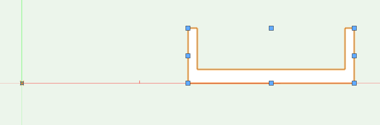
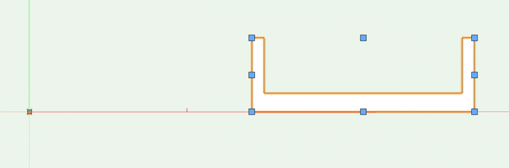
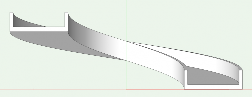
You could try using a sweep. In a front view, create the profile shape and place a locus to define the center of the sweep. Select them both, use the Sweep command (in the Model menu). Make sure to give the sweep a pitch. The pitch is the change in height of the sweep when swept 360º. If you sweep 180º, the ramp will go up half the pitch. The profile and locus before creating the sweep: The sweep with a 180º sweep angle and 24' pitch:
-
Placing models with CameraMatch in distorted photos
Matt Panzer replied to erminio's question in Troubleshooting
You're welcome! Yes. Not fun. That sounds like what I used to do before developing Camera Match. 😉 Good to hear you were able to get something you can use. -
Placing models with CameraMatch in distorted photos
Matt Panzer replied to erminio's question in Troubleshooting
Hi @erminio, Lens barrel distortion can be corrected in image editors. There's an inexpensive application called PTLens designed just for this and has a huge database of camera and lenses with correction information. If you open an image taken by a camera and lens from its database, it will auto-correct it for you. I haven't used it in a few years, but it worked wonderfully when I did. It was well worth the price for me (I think it was 25 USD). As for matching images that have been stitched together: All bets are off. The problem with this is that each image has its own set of vanishing points. Maybe you can get something close enough through trial and error, but I make no promises. The preview object's perspective strays from the control lines when the vanishing points are positioned in an impossible (unrealistic) configuration. The pure math behind it all cannot calculate the view because the object could never be viewed with the three vanishing points in those locations. Usually it's the most parallel pair of control lines causing this problem. In your case, this would be the blue (vertical) control lines. Moving the top end of them slightly to the left or right might help correct the issue. Keep in mind: The closer to parallel a pair of control lines are, the bigger the change when changing the angle of them. -
Change the planar (2D) objects within the symbol definition to "Screen Plane". Objects on other planes are considered as part of the 3D component.
-
Glad to help! 🙂 The "printed" size of the markers should be the same across viewports regardless of the viewport's scale. IOW, a marker seen in a 1:50 scale viewport should be the same size (as seen on the sheet layer) as the same section line marker in a viewport of another scale.
-
It's "just the way it is" - at least for now. It's the nature of the current hidden line render technology. As I mentioned previously, we'd like to have something similar to the technology we created for the "Generate 2D from 3D Component" command (in the edit mode of symbols).
-
My only guess would be that it has many more facets due to the curved profile. honestly, I don't know. Just a theory. Yes. This is why I suggested an Extrude Along Path. they render more predictable. However, it looks like you managed to get fewer facets in hidden line render with sweeps. Just less predictable. Are you saying this is how I fix it? If so, can you please give more details as I could not find that command. Thanks No. This will not fix it. The command I'm referring to is within the Edit mode of a 2D component of a symbol. The command creates a "special" hidden line" conversion that produces curved 2D lines (in the symbol's 2D component) from curved 3D geometry. It generally works very well, but can have difficulty with some geometry.
-
Right. There will always be faceting because the hidden line renderer ultimately results in line segments. Sweeps are faceted geometry to begin with but Extrude Along Path objects are not. I believe the unpredictable behavior your getting with a sweep is due to how the hidden line render interprets the huge number of facets your sweeps already have into its own rendered facets.Ultimately, we want to have the Hidden Line renderer provide curved lifework for this. We can do this within symbols (in VW 2019) when using the "Generate 2D from 3D Component" command. The reason we don't use this technology elsewhere yet is because it's slow and sometimes produces errors when interpreting curves.
-
You could try using an Extrude Along Path. They create true curved geometry that should render more predictably according to the 3D conversion Resolution settings.
-
Door & Window Styles in Symbols not Retained in VW 2019
Matt Panzer replied to willofmaine's question in Troubleshooting
It could very well be there in a way that my search didn't find it. I though it'd be better to be safe then sorry, so I enter one. -
Door & Window Styles in Symbols not Retained in VW 2019
Matt Panzer replied to willofmaine's question in Troubleshooting
I have not personally heard of this one! I was easily able to reproduce this using your steps. A quick search in our bug list did not turn up anything that looked similar so I went ahead and submitted one to make sure. I'll make sure it gets in the right hands. Bug filed: VB-159027 Plug-in Style: Styled instance in symbol becomes Unstyled -
Set your viewport to Top/Plan view and you should have it. The layer stacking only works in that case.