VIRTUALENVIRONS
-
Posts
828 -
Joined
-
Last visited
Content Type
Profiles
Forums
Events
Articles
Marionette
Store
Everything posted by VIRTUALENVIRONS
-
There could be a few reasons. Off the top of my head, I would go to the 3D Power Pack module and select rebuild curves. Rebuild will smooth out the curve. Add points if necessary.
-

Upgrading - There is NEVER a good time for this.
VIRTUALENVIRONS replied to digitalcarbon's topic in General Discussion
I had a problem in 2022 where it hung up or crashed in a similar fashion. I did a reinstall and the problem persisted. Then I did an uninstall first and then a reinstall, good to go. I appears the problem lies in a Preference file somewhere. It has not happened since, and It may have been handled by an upgrade. But, the point I am trying to make is that if you have done a re-install only, the problem will persist because the offending Preference file still remains somewhere. -
Extrude along path not working 'as expected'
VIRTUALENVIRONS replied to hollister design Studio's topic in General Discussion
Lots of info here. Although extrude along a path with most users begins with a poly line or just a open polygon and planer profile, the moment you hit "OK", it becomes a NURBS curve. If you edit the path, you will see it has become a NURBS curve, curiously not the profile unless you started with a NURBS profile. Everything in Vectorworks is NURBS based as I understand it. Extrude along a path is just loft with one rail, only much better. I only use loft with one rail when accuracy is not required. It has been my experience that simply beginning with a NURBS curve eliminates a lot of unforeseen problems if the path is tricky. The problem is how VW's decides to change your curve into a NURBS curve. For example, if your path Is a polygon, after you do the EAP, go to edit path and then look at "rebuild nurbs" in the 3D power pack mamu. You will only have a few points. It may be sufficient, but it may not. -
"Always room to grow" very true words, and another one that I hope to aspire to it, "never too old". kind regards....Virtual
-
Hi Jeff, Not really interested in a job. The part about "well retired." I am 70 years old next year. Retired for 17 years. I did find it odd that VW would contract me after all these years for help on 3D modelling? Just curious, did anyone from Vectorworks contact you on this issue? Seems to me you would be a prime candidate to write advanced 3D NURBS tutorials.
-
Yes, just a beginner. When it comes to NURBS modelling, everyone including me is a beginner. I see you are a trainer. Do you have a website?
-
I have several Youtube channels. One has well over a million views and 4000 subscribers, but I do not monetize in any way. I am long and well retired. I have a permanent NFR of 2022, but use 2018 most of the time. Most of the time being maybe a few days a month. For the last eight years or so I have been going back and forth with Vectorworks on the issue of explaining NURBS modelling. Finally last year, VW's contracted me to write two tutorials on how to build fairly complex objects, so they could get users interested in NURBS modelling. But, in the end, they decided not to use them. They have and will use them for promotional purposes, plus for their own tech people I am assuming. But, they are quite happy for me to post free NURBS tutorials and I may. What I am trying to do is gauge interest in NURBS modelling, so If I see a door open, I post something. I apologize if this is offending you in some way. My history with Vectorworks -1986 - became Minicad's first 3D beta tester. There was a 3D component to the first Minicad. ~1995 contracted by Vectorworks to write paper chapter on 3D animation in Vectorworks -Wrote tutorials on how to transfer 3D files to CINEMA 4D before "Send to" button using dxf. -Worked with Nemetschek Germany to implement "Send to" button. -Wrote tutorials for "send to" button. -Last year, wrote tutorials for Vectorworks on NURBS modelling.
-
Hi Jeff, I did understand that, but when you brought up "have you considered purchasing the model", it opened the door to other alternatives. It seemed that way anyway.
-
My apologies, I got caught up in the Bomber design. I should have posted this short tutorial. I did this for a colleague several months ago. I believe it shows how to build what you want with minimal requirements.
-
Although subdivision is interesting as a Vectorworks visualization tool, I am assuming you don't need the Raider for a landscape design. I am thinking you are exporting to another program. If not, I stand corrected. If you are exporting, then you need to break down your parts so they can be textured, or animated etc. If this is the case, 3D modelling is going to be much easier. The Bomber below was modelled in Vectorworks and sent to C4D.
-
How do I create a shape from a series of cross sections?
VIRTUALENVIRONS replied to Bruce Kieffer's topic in Solids Modeling
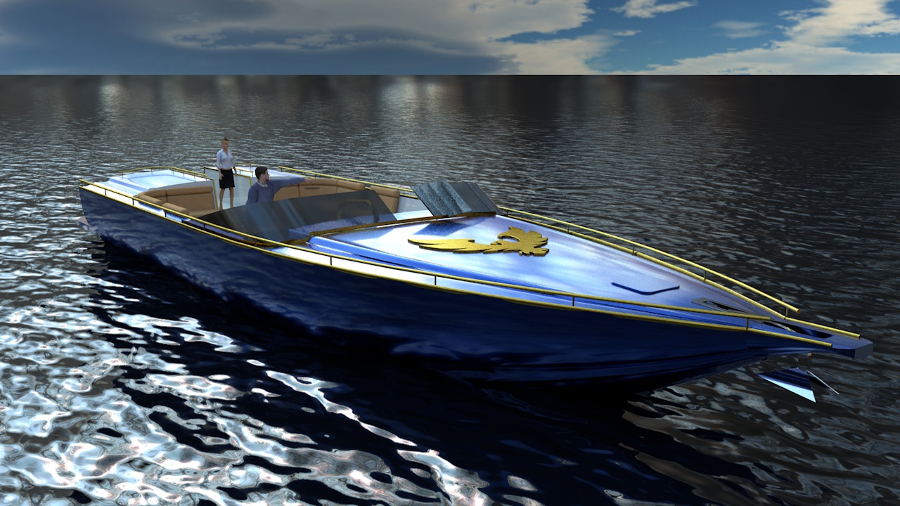
Hello all, Coming to this post late, but it is an area I work in. The boat below was built in Vectorworks 2015 many years ago and rendered animated in CINEMA 4D. NURBS are not well documented and can be misleading. Extrude along a path and the 3D locus point are your friends in this area. Have you created what you need? -
Your original method would/could work, but you not snapping to points that are on the same plane. They may appear to be, but are not. There are many ways around this, but one from what you have described is to: First - Select the "3D locus" and put one wherever you want the edges of your garden bed to be. Essentially doing what you first did, but just put in the 3D points. Second - Then use Ccustom Selection>Type is 3D Locus" to select them all. Third - In the Object info box, set their "Z" to the same elevation. Fourth - Then pick off those points with your 3D polygon tool.
-
This might be something better remedied at the point of creation. Can you provide a little more info on how and what you are creating?
-
I believe the reason is (and I could be wrong) is that this function will not work any other way. "Extrude Along a Path" is just "Loft with one rail", but is editable. In order for this function to work it likely has to converts the 2D path to NURBS. Otherwise this function might not exist.....and it's a good function. A work around for this is, keep a copy of your original path (polygon) in memory or in another layer. Modify the path in that layer. When you do an "Edit path", delete the existing path and paste the new path in. More tedious, but it works.
-
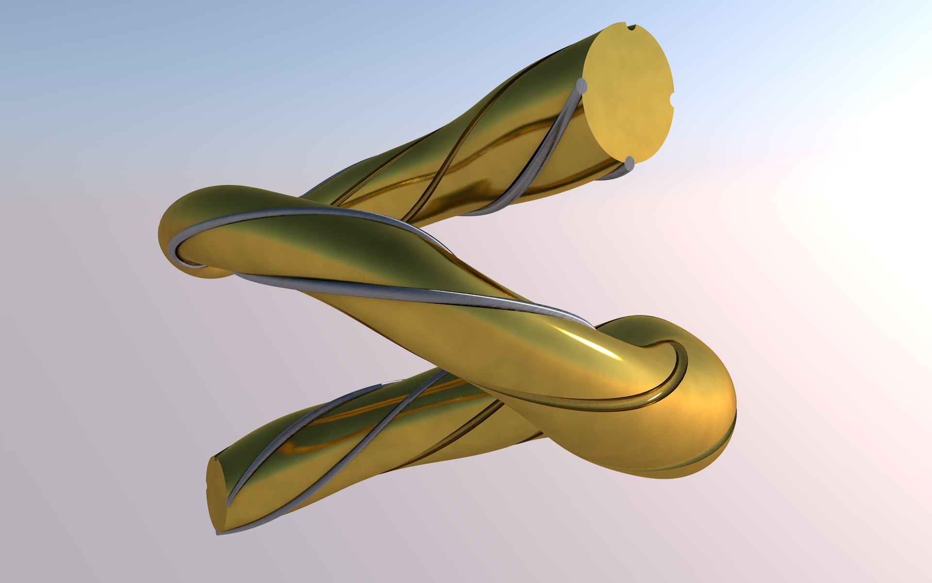
Hi Piotr, I have been doing 3D printing recently to help a friend. I am not sure what he uses to print with, etc. We use either Step or STL. For homes or "vector linear" models, Step works very well. STL files for more free form models. We are not having many problems, but I think this is because I never use the automated tools for building models, (walls and roof, etc). These are great tools for creating design dwgs, but for 3D printing, I think it is best to keep the models as close to the native format as possible. The only problem we run into sometimes is surface normals get flipped, but I am assuming your software can handle that. Enclosed are two images, Step for the lighthouse and STL for the gingerbread man. The Lighthouse was made using the standard 3D tools and the Ginger Bread man with NURBS tools. The STEP files had problems handling the white frosting. NOTE: it is possible these issues could be limitations of the printing software. There is a learning curve.


-
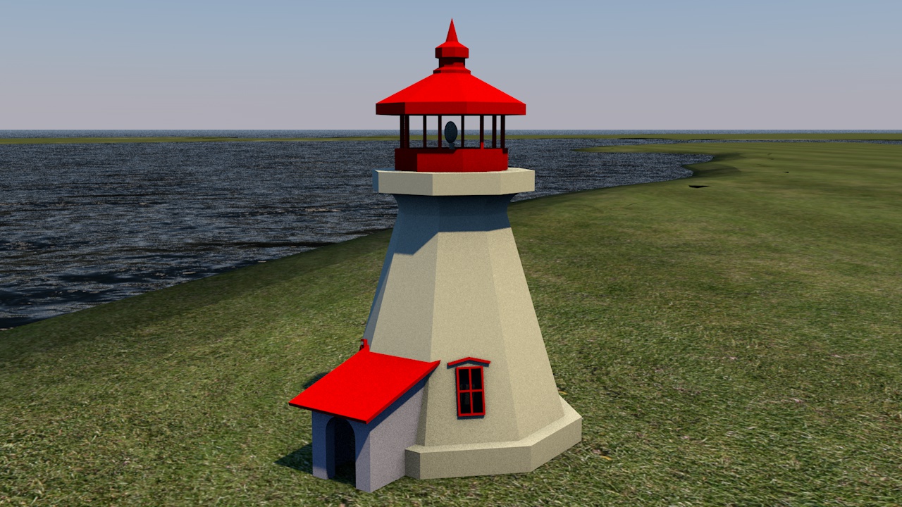
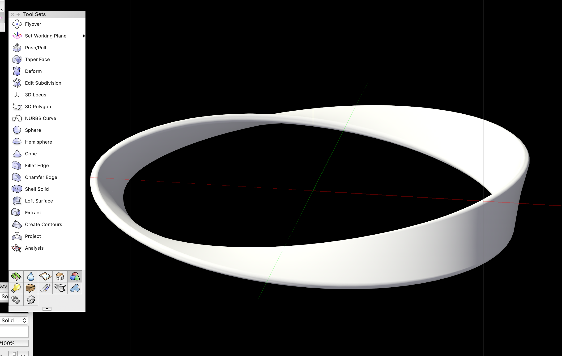
Hi Line Weight. I took. look at what a Mobius curve is. Learn something new everyday. I modelled his up. Is this what you are looking for?


-
For those following this thread. Landscape design came into play in this thread. Below is a video that shows how Vectorworks was used to recreate a 105 year old Battle Field from WW1. That battle field is approximately five square miles and includes about 120 miles of trenching, both Allied and German. The various military pieces were all modelled in VW.
-
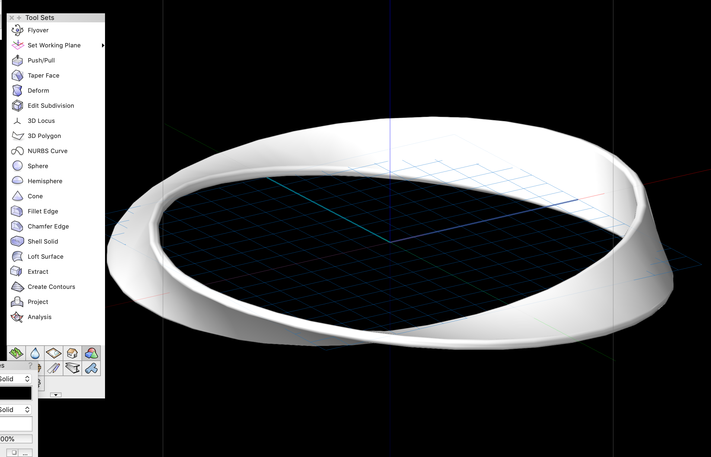
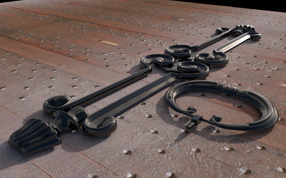
Hello "Line Weight". I am new to this forum, never sure who I am responding to. I have never tried a Mobius strip. First time I have ever heard of it. I would hope that I could make it, if not "kudos' to those who can. It appears it would be similar in making the image below. Like the Mobius strip, it has no engineering value, but it was a test for a project. I no longer work, I am 69 years old and use VW at the most a few weeks a year. I also use CINEMA 4D when I am working. I use the two as one application. The image below was modelled in VW and rendered in C4D. regards....Virtual

-
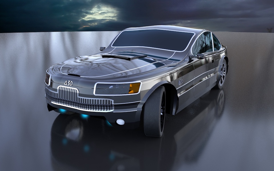
Hi Jeff, I am not a Landscape designer. I did not really think the fellow who posted the initial question was either. So, I will defer to your take on this as you are a Landscape Architect. My background is engineering. I am long retired, but keep my hand in the game. I am a Vectorworks 3D and 3D NURBS specialist. I wrote advanced tutorials for Vectorworks last year, but after being reviewed by the various factions, they decided to use them for promotional purposes only, You may have seen the Chair Video. You can find the tutorials on the link to my Youtube Channel. It will take you to a video, but you can find my channel from there. There is a downloadable file that comes with each tutorial. The two tutorials in question are "Chair" and Bike Pulley Wheel", Below are some other models I have done in Vectorworks. There is a link to 20 minute video at the bottom that shows the car being modelled start to finish in Vectorworks, then rendered in CINEMA 4D. In regards to C4D, I worked with Nemetschek Germany to implement the "Send to" function. kind regards...Virtual Link to Car tutorial


-
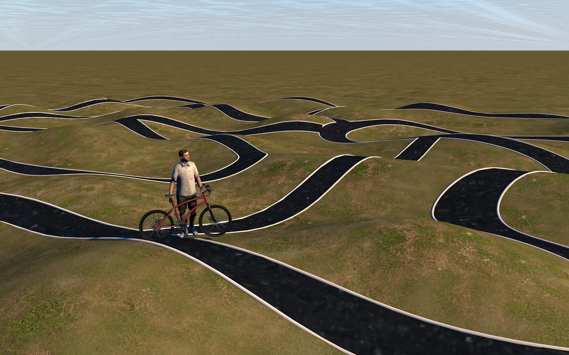
Your initial post showed two variations of a bike path. This one is much easier than the second. See Below After you decide what method to generate the topology you have shown, simply create your path directly above it and use the "Project Tool". After that you can Extract Curves to create borders, lights, railings or whatever. See final image below.

-
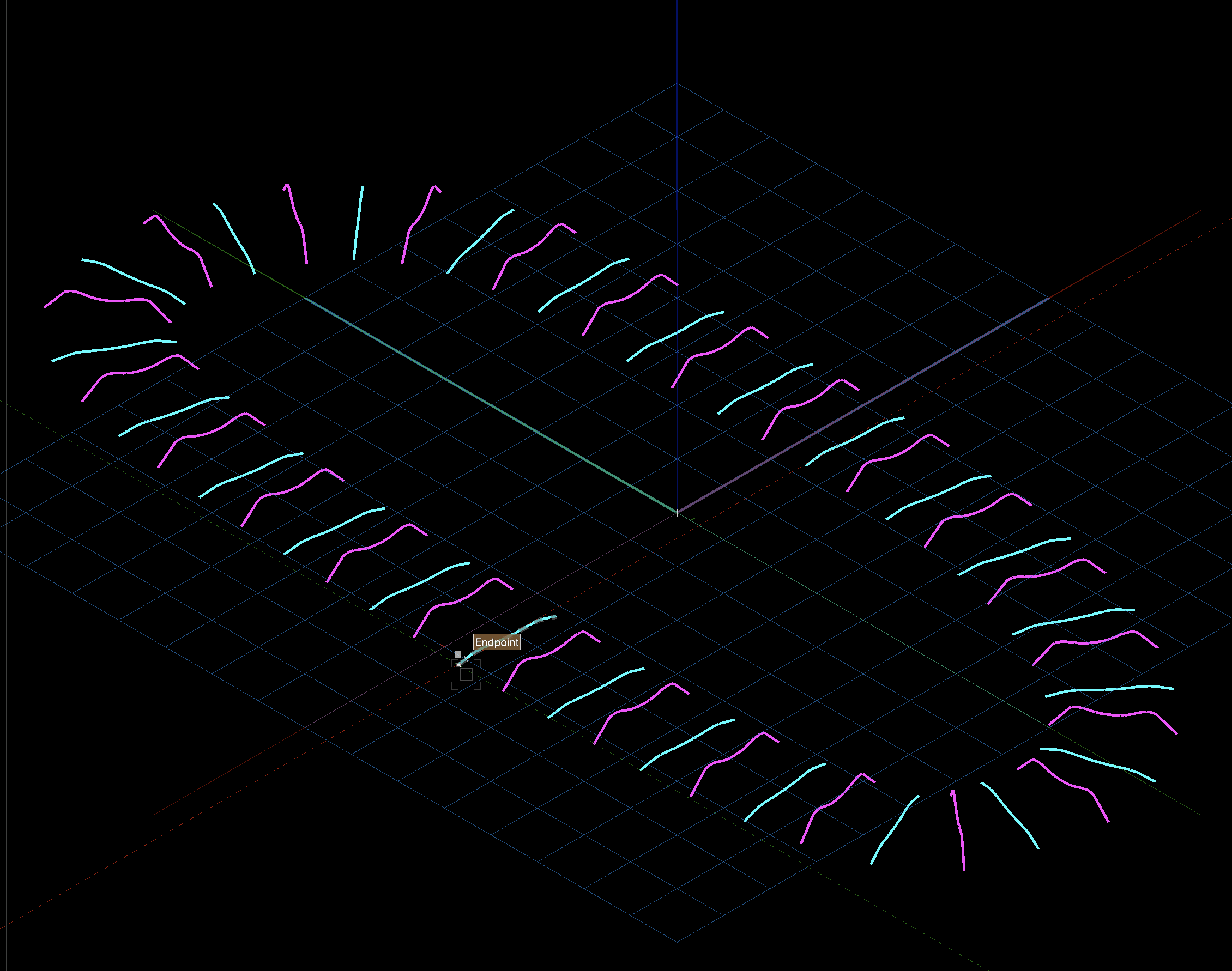
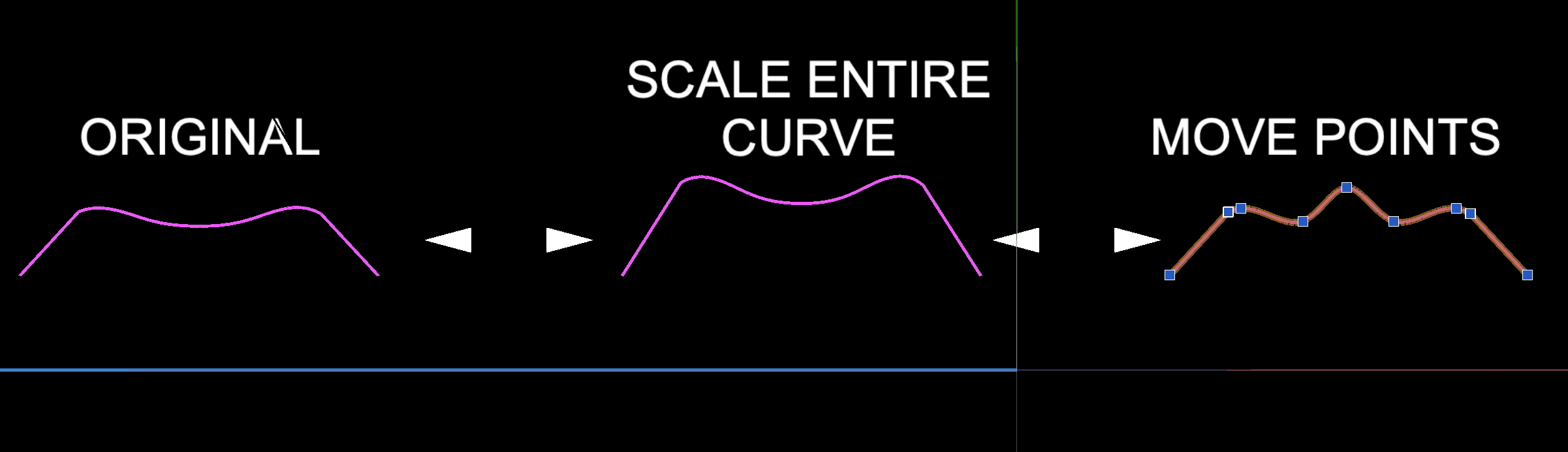
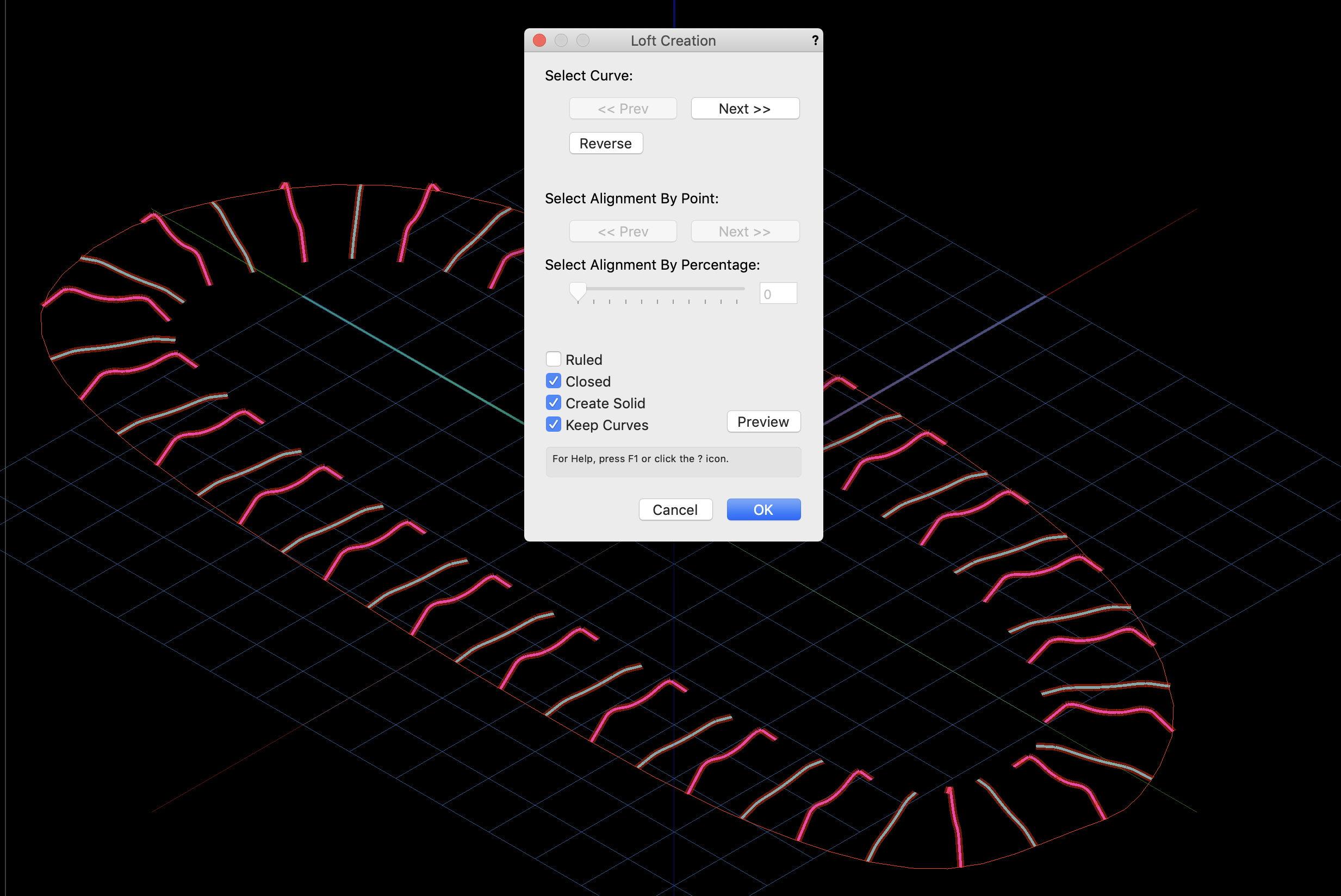
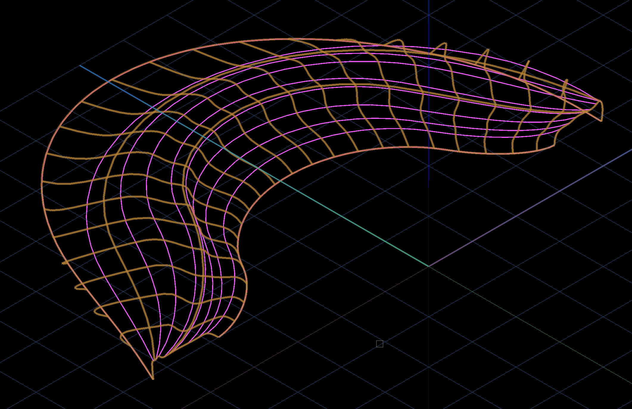
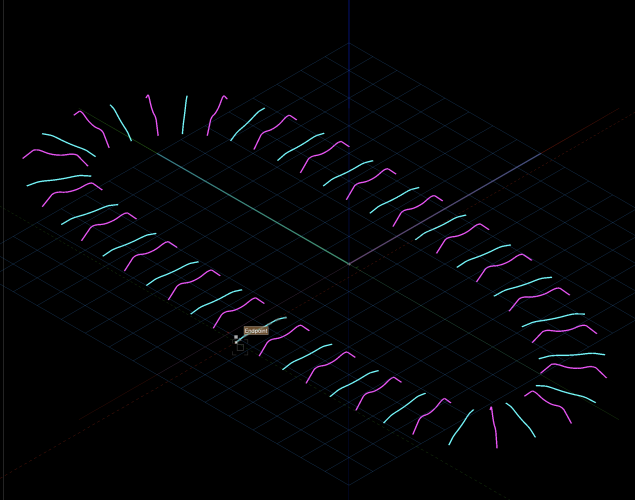
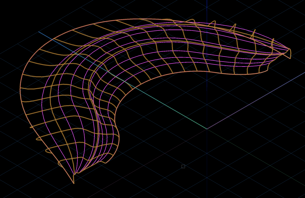
Hi Jeff, thanks for sharing, thought I might do the same. First of all, my method is not easy, but if offers 480 control points with topological elevations that can be transferred to a Landscape person. I started with two curves depicted below in blue and magenta. Blue is the flatter curve for the troughs. Although it would appear that positioning these curves is tedious, it is not, there is a quick method, but that is another session. I Each of these curves has nine control points as shown below. You can either scale the entire curve or the just the points. Loft curbs with settings shown. The half pipe was made in loft curbs again, it could have been loft with two rails, either or. Then mated and joined with Add Solids.


-
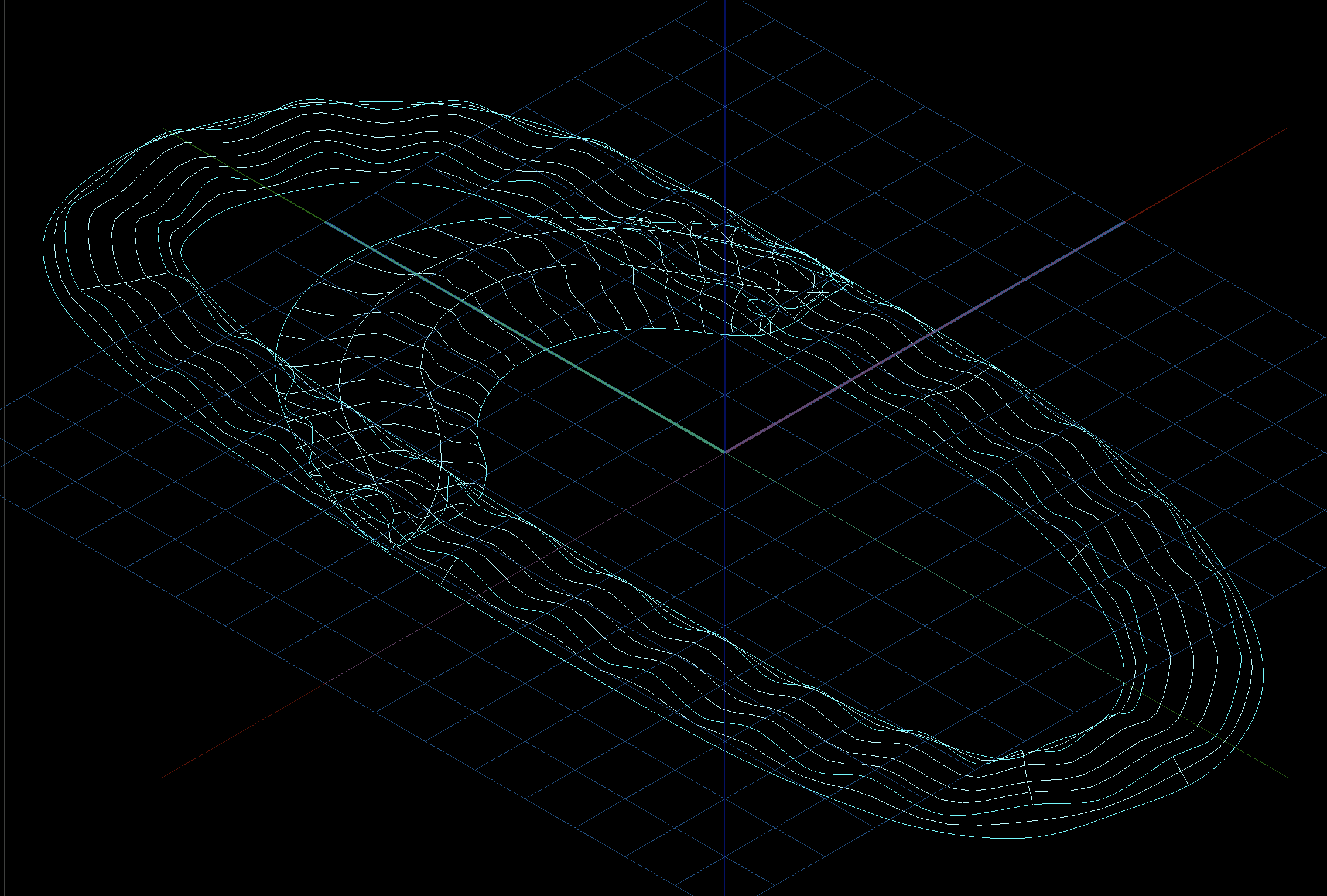
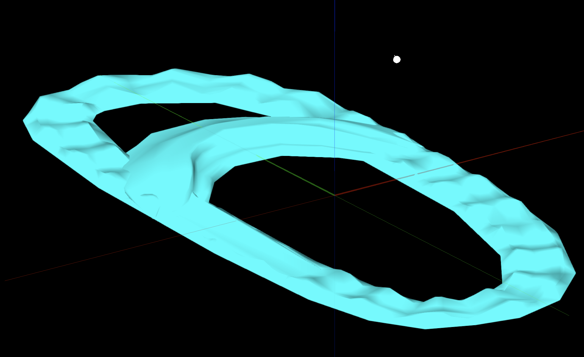
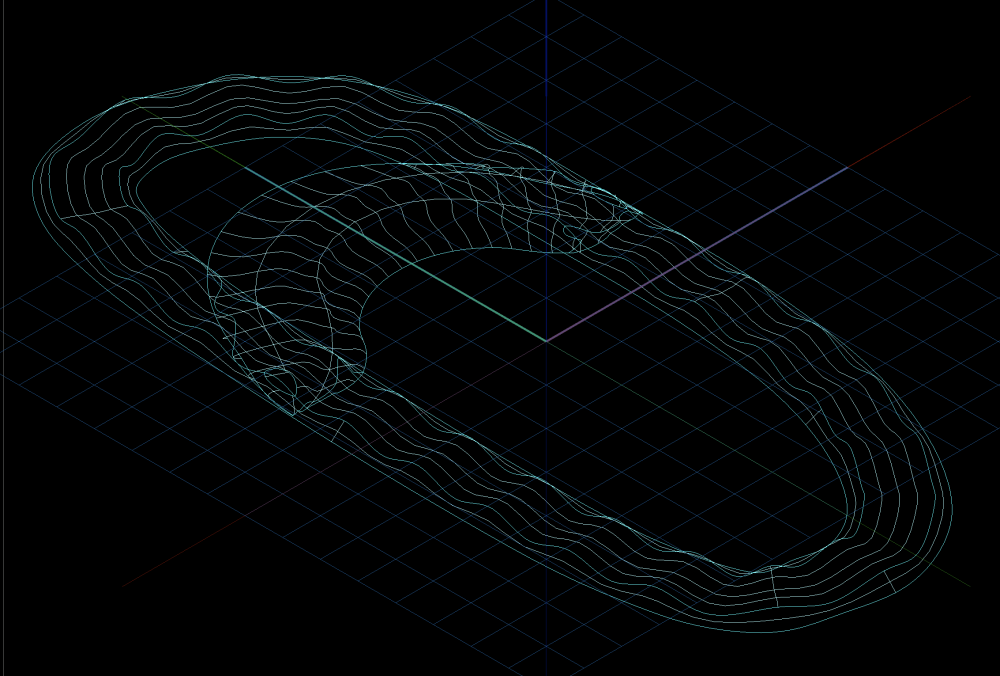
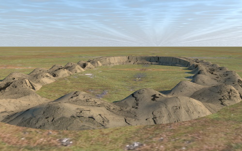
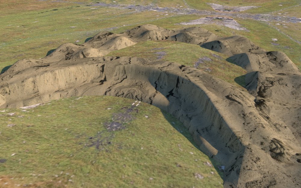
Your project was interesting. I started thinking about it. Birail is one option, but you quickly hit a ceiling where you can't modify any more. Loft nurbs (no rail) has the most control of the two. I built a track based on your first image that included the half pipe in the background. There are approximately 350 control points in this model that can each be modified and the info transferred to a landscape person. If you want more info or the file let me know.
-
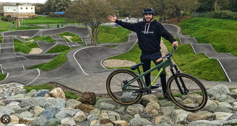
The two photo's you show are somewhat different. The first track is built over a roughly flat surface and the second a sculpted surface. I am thinking you need to model the track only, is that correct? If you need to model the track only, it would be much easier. Which version do you need? Have a look at this video. It shows how to create complex sculpted surfaces in Vectorworks.
-
Using the NURBS advice is the only method forward I can see and you are getting some good advice. Have you tried using the outer surfaces and the shell tool. That would also appear to solve your problem. Question, do your inside edges need to be beveled so the joints are flat. Some of your surfaces project outward so a straight loft or shell will cause an intersection of surfaces on the inside. You could use Subtract solids for each of these to get the correct bevel.
-
There are about 10 or more different ways to make this object. That is the beauty or problem (which ever way you see it) with 3D modelling. The step by step given in this thread is a good one, but as you are a novice, it still may be confusing. You could make this entire object with a single circle in combination various tools, but each user may vary widely. You will need to find your own method. The link below shows a complex object being made by a half circle. It may give you some ideas on thinking outside the box.