Benson Shaw
-
Posts
4,316 -
Joined
-
Last visited
Content Type
Profiles
Forums
Events
Articles
Marionette
Store
Everything posted by Benson Shaw
-
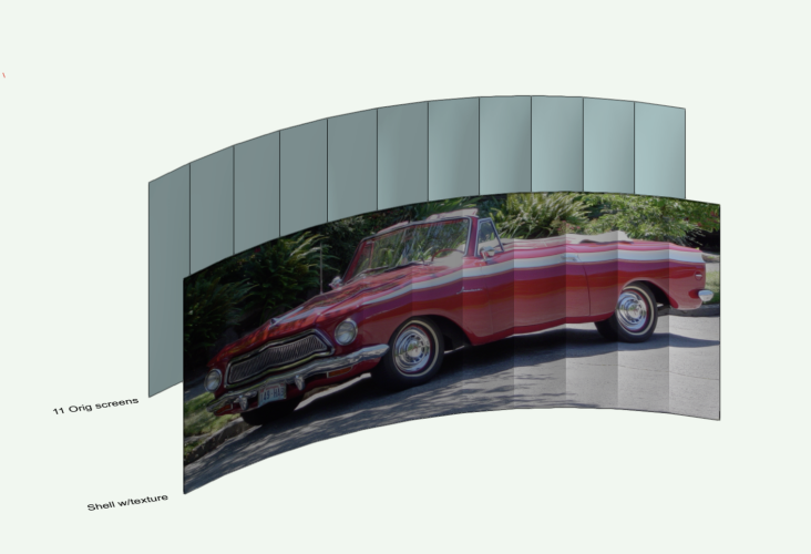
Use a cheat? Try the Shell tool in 3d Tool set. Shells comprised of several source surfaces texture as a single surface, in Plane Mapping. For safety, dupe the whole set of screens. Offset or move to a new layer. Engage the Shell tool. Set the thickness pref to something small - eg 5mm or 1", or . . . (adjust later as needed) Shell can grab many types of surface, even surfaces contained in groups or booleans. Click each screen with Shift key held until all screens are highlighted. Release the Shift Key. Click the green rectangle (upper left in Mode bar). Note: The original surfaces will be consumed by the Shell (hence the dupe). To retrieve them, Ungroup the Shell. Apply texture to the shell via OIP Render tab. Mapping = Plane Scale via slider or numeric as needed. Adjust texture position via Attribute Mapping tool. or numeric offsets. Front view best. Move the shell to match original position of the screens. -B
-
Doh! Jeff beat me to it. I've had some fun with curtain walls recently. Could work here. Make all panels Open to defeat the glass. Adjust the frame member dimensions. No caps might be best. -B

-
Drawing Curve and identifying the curve wall deg
Benson Shaw replied to clng's topic in General Discussion
Oops - no responses since Tuesday! Here's a clunky way to do these things. 1. The 6: My easiest, most controllable path is via the Polyline Tool>Tangent Arc mode. This is, I guess, more of a Volute than a spiral, but looks OK. Also possible with the Bezier and Spline modes, but more points to edit if not satisfied. The Spiral tool can also be a base object, but inner point shows uneven curve, and the flyaway "riser" breaks the regularly expanding spiral. So edit with split tool, rotate, add arcs, etc. big hassle. This curve can be transformed to a wall, via the Create Objects from Shapes>Walls. This creates a series of tangent curved walls. Can have components, openings, etc. If only 2d needed, use offset tool. 2. The angle/degree: I think you want the angle between LED units? This will vary at each pair because continuously varying curvature. But, to determine the angle between pairs, use the Angle Dimension tool>Reference Lines mode (3rd mode). See attached. 3. I think there might be a script floating around here for distributing things at constant length chords along a curved path. Anyone? The distribute tools use the arc length between stations. Eg Duplicate Along Path and Surface Array will leave spaces or overlaps at the joins, or stretch/compress the array items. I think doing it by hand with the Smart Cursor will be quickest in this situation. Create snap points by tabbing into the Length field and adding the chord value (width of array item). See attached. Good luck! -B The 6(1).mov The 6 - angles(1).mov -
Saved view page orientation restore relocates the user origin? Doesn’t seem like it would, but might be worth checking. -B
-
@VIRTUALENVIRONS First, thanks for your several posts showing your NURBS techniques. This process of tracing an original curve to regularly spaced loci is quite helpful in many situations. The traced curve you suggest here indeed lofts and shells nicely - pick each facet. Or Add Solid and shell all in one go. But, the shell is, I believe, unusable in this context because of gaps and uneven joins between non continuous facets. That's the nature of a shell - normal to each surface. Maybe a small fillet at each corner point would correct. That's something to test another day. I'm trying the walls with fit to geometry next. But might be a couple days. -B
-
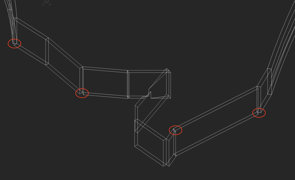
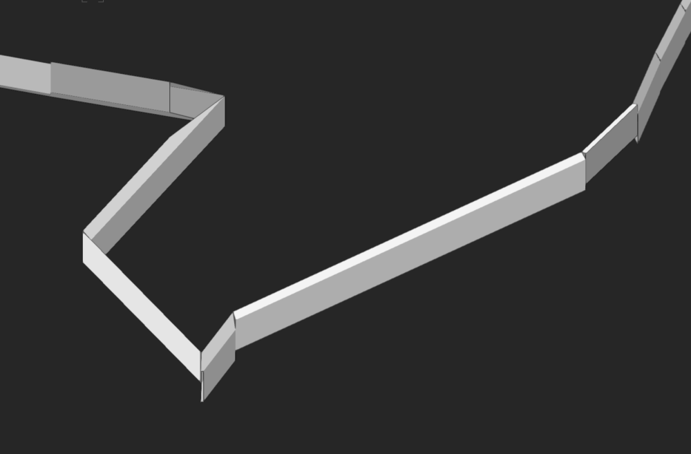
@jeff prince Cool, thanks for looking at my file! Ummmm . . . I don't think my post above contains any phrase about "...confusing statements". Especially unlikely in that I didn't find any confusing things in your or other posts! The EAP profile in your file is a straight NURBS curve. It has no thickness. Same resulting shape as the loft no rail. Great for visualization. I got there easily, but am also exploring thickened context. Edit your profile to include some thickness, eg a NURBS or 3d poly rectangle, to see missing faces and mismatched segment joins. Attached find image and your file modified with thickened profile. @all - So far this thread is fun vwx modeling technique. I believe underlying concept derives from a roof top park DTM? I wonder what is intended or possible retaining system for the proposed landscape and users thereof. And efficient modeling to match. -B Isn't difficult 2.vwx
-
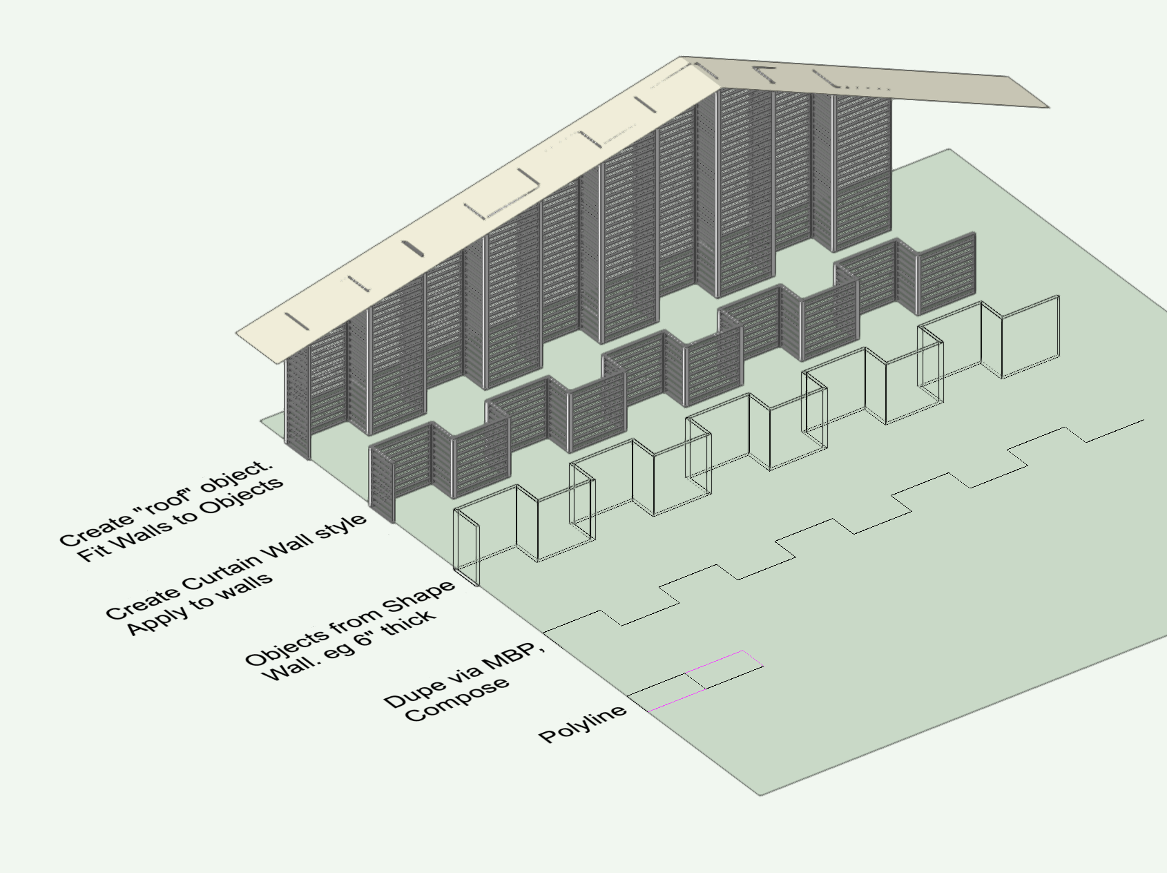
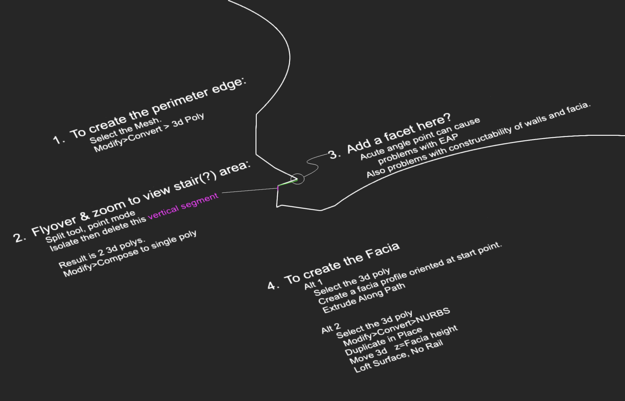
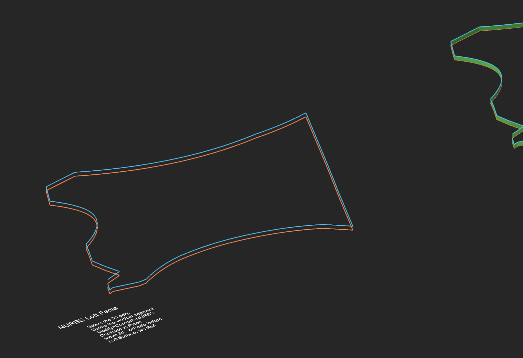
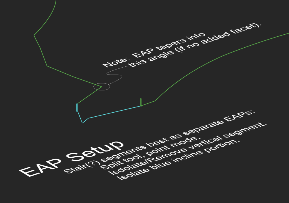
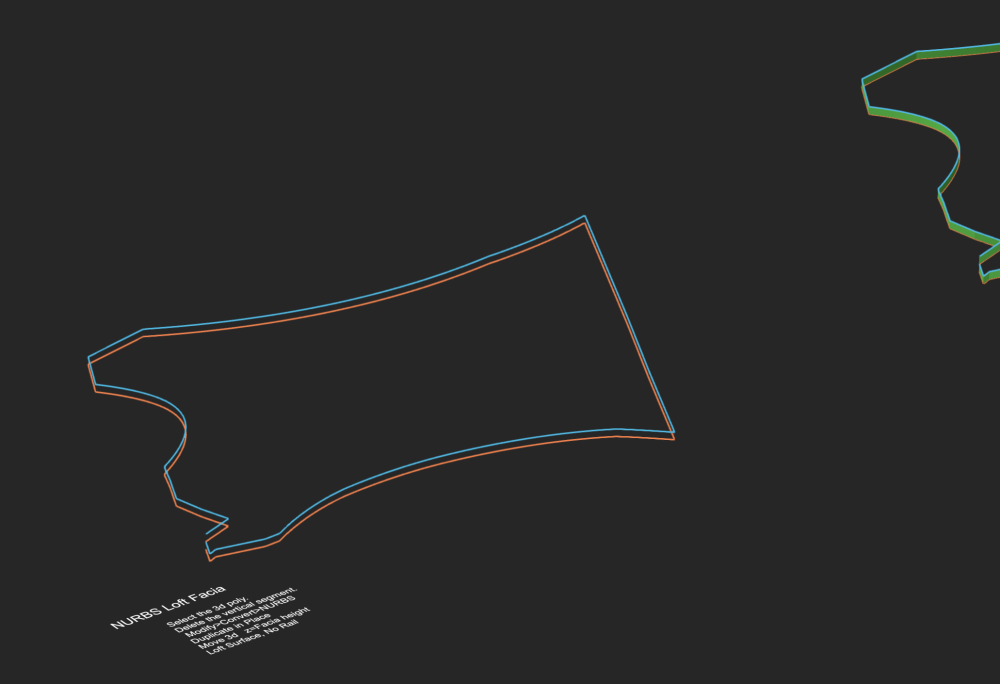
Great discussion and challenging question. Some details from my explorations: 1. Using the perimeter of the mesh to create a facia seems promising, but many problems, esp at that entry/stair area. Other possibilities I did not try - A) Add a component to the original site model (thickness of facia height). Convert a copy to Mesh and isolate the edge shapes. Problem is it has no thickness. B.) Use the 2d layer plane roof outline as source for new walls. Fit the walls to the mesh once at top. Move the mesh down and fit walls to bottom. Walls can have thickness or components for the facia. Acute angle at stair will need special treatment. 2. Using this mesh, my EAP struggles to complete a continuous form. Gaps and miss fits where inclines vary. Great for distant visual, but not so good for construction. I could not easily solve this. Lots of extra modeling required at many joints. 3. Lofting (No Rail) also great for visual, but no thickness. I tried Birail Sweep too, but no joy except in smaller sections, so more modeling to correct at joins, similar to EAP. Too bad this loft doesn't shell. Even converting to Add Solid and Generic Solid will not shell the whole object. Also, shells go normal to surface, so gaps will need filling (Maybe Stitch and Trim could help?) 1st step is getting the perimeter. Easiest is Convert to 3d Poly. Mesh evaporates, leaving the perimeter. No need for Extract tool. Some files attached. -B Northplace Facia b v2023.vwx

-
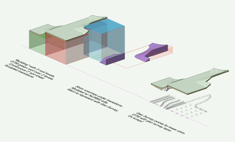
Modeling is most direct path, fer’ sure. Might also help to split the site. Separate DTM at each roof level might facilitate a flat exist with contoured proposed. Could the shims be represented with a tapered component? Haven’t investigated tapers yet. I’ve seen some examples where a thin “ghost” component is created above or below the geo components, but no success for me so far. I’m still curious about a geo survey spreadsheet file. Never saw one. What format needed in vwx? What info is in the columns? Can I collect that data from array of 3d loci via a vwx worksheet and save as a geo survey file? -B
-
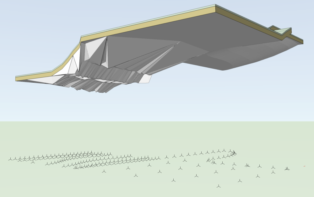
Reading some recent posts about rooftop gardens and parks made me test and explore. Which started an investigation the DTM Geological Survey component in an imagined, simplified context. Specifically, I'm trying to represent the volumes (shims) between soil sheet and building roof. Several comments and questions: 1. In the Geological Survey Component Edit, new Geo points can be placed by snapping to DTM or guide objects and locate with 3d elevation. Leave then reenter the geo component edit and all geo points revert to layer plane. They are difficult to pick for later edit because they all look same. Why not have them stay where placed? Or, better move to assigned depth in OIP component fields. Or? 2. Geo points have OIP data fields (thickness/depth) for geo component and components above and below. An additional workflow could be to make array of 3d loci and transform them to geo points, then paste them into the geo edit pane. Or somehow use the array to create a geo survey for import. I can paste a guide object (eg a contour) into the geo edit, snap new geo points to it, then delete the guide object. Works OK as does the DAP tool to spread points with similar depth data. 3. My tests with single geo component does not make a consistent surface/volume. The geo points seem to connect intermittently to the next component up, or even show edges extending below the OIP point value, rather than connection to adjacent geo points. What's the workflow to create a geo component surface conforming to the points? Any comments or workflow suggestions appreciated. -B 517644643_RoofGeocopy.vwx
-
Site model skirt shows holes when cropped in VW2023
Benson Shaw replied to Tom W.'s question in Troubleshooting
I looked at 2 files I thought had blank areas in DTM skirt. Both Files now show fully opaque. Maybe these were fine and some other file showed the problem, or a recent update solved it? One had no grade limits. Copied crop and Object from shape>Grade Limits, update DTM, no change in Skirt opacity. More things to test: DTM, or errant object(s) far from origin? or mixed up georef? Hardware or app problem needs restart? External device drivers? Multi screen conflict? I give up until I find the problem again. -B -
Site model skirt shows holes when cropped in VW2023
Benson Shaw replied to Tom W.'s question in Troubleshooting
I have seen transparent sections of DTM skirt. Not all DTM. I think the transparent areas are not always same location in a particular DTM. No fix, but I will see if I can find or induce it in a file that has the problem. Now I need to find the file! I wonder if there is some interference from a Grade Limits, or other modifier, close to or overlapping the DTM crop. Will check that also. -B -
Why do my faucet symbols keep moving down to the floor?
Benson Shaw replied to Ed Wachter's topic in Architecture
Any idea of trigger? Eg CPU reboot, or vwx restart, or file close/open? Or save view toggle? Or??? Is there some 2d object in the 3d component of the symbol that causes regression to layer plane? Eg a 2d Locus? Does object behave properly if symbol is converted to group? Or to group, then Add Solid? Or then convert to Generic Solid? Post a sample for forum testing? Rather annoying for bathing if shower head at or below shower deck! -B -
For posting eps in forum, try changing the extension from eps to pdf or other (and explain the switch). Or zip it. also, is it possible to fool vwx with same trick? what happens if extension of orig eps file is switched to pdf, then imported into vwx? (Probably best to save/close all other vwx files first, in case crash!) -B
-
@digitalcarbonThanks for sharing! If inclined, please keep us informed about adventures in OnShape. -B
-
I think the Align 3d command was added to the Align feature set after the OP date and discussion. This command can help, I think in any view, but may need some fiddling. Also has problems with mixed 2d3d selection. If objects are all above z=0 (or other desired z value), then place a 3d locus or other object at z=0 . Select the locus and objects and run the command with only the “z Bottom” option active. The objects move in z only, ending with lowest point of each object descending to z=0. Locking the guide object may help. If objects mixed above/below desired z, group them then enter the group and run the Align 3d to bottom. As earlier posts above, move the group up to z=0 by any means, eg MBP, Move 3d, drag, Align 3d again, etc. One could also Align 3d the selection to bottom, temporarily create a symbol of the selection. Edit the symbol definition to adjust the insertion point to z=0. Use OIP to adjust the instance z. Then convert to group and ungroup. Risks of xy movement in the symbol edit phase depending on method, view, etc. Multi view panes is another path. Original perspective view, plus another in orthogonal side view. Close out the side view without altering the perspective. But all the above still depends on align, or finding exist z value for calculation, rather than a send to z=0 (or other). I support idea for command/script/enhancement to move selection in z so that each member of selection ends up with bottom or ctr or top at specified z value. -B
-
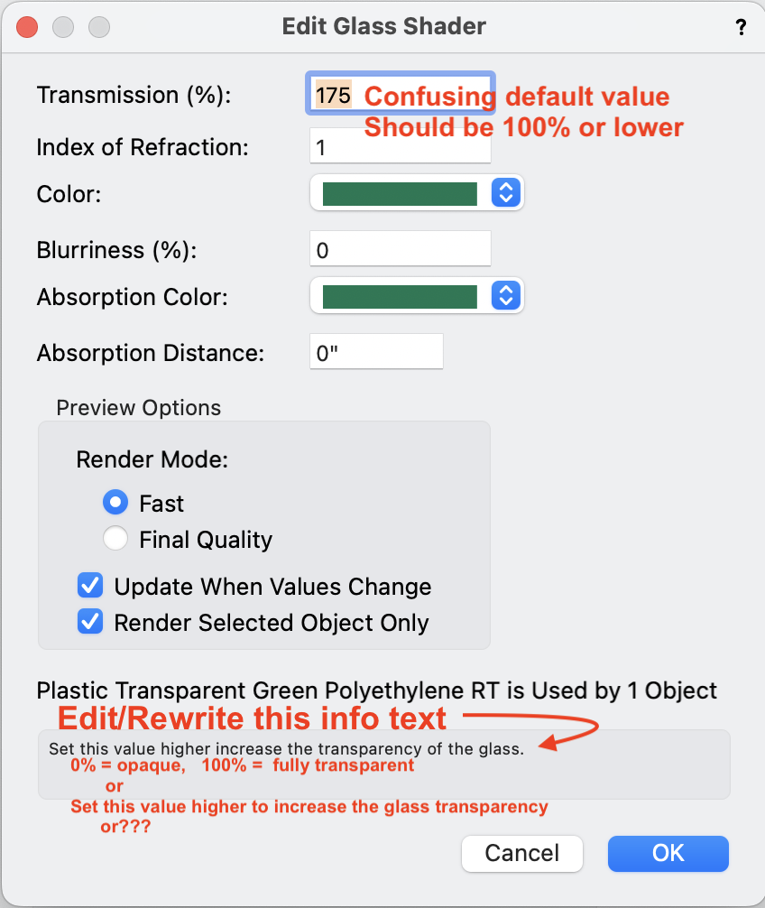
I just spotted some confusion related to a vwx standard content texture: Plastic Transparent Green Polyethylene RT. I think this applies to any texture with a glass component. Duplicated and edited to achieve various transparencies via the Transparency Shader value for Transmission, eg 10%, 50%, 100%. #1 - The default transmission value is 175% and the result is an opaque surface. Why is this the default value above 100? Seems is should be 50% or other between 0 and 100. #2 - I know that, in general, vwx data fields for percentage can accept values higher than 100. Usually the higher values produce greater effect. For Transmission, the info text at bottom of dialog, suggests that higher values produce higher transparency. In textures with Glass transparency, 0% transmission is opaque, 100% is clear . . . but . . . 101 and above is also opaque. ??? I would imagine the higher values would just be fully transparent. #3 - The info text is not exactly misleading, but could be amended for clarity and better use of the language. World class software should have world class writing throughout. I imagine this text has not been reviewed for many versions of vwx The dialog text as presented: "Set the value higher increase the transparency" My meager suggestions: "0% = Opaque 100% = Transparent " (or Fully Transparent, or Clear, or . . .) "Set the value higher to increase the transparency" I make no claim to world class word smithing. Just want the software to best represent itself in all aspects. Note that "set", in English, has more definitions or senses (about 430 as a verb) than most other words in English. Best to limit or avoid where possible? -B
-
Translucent extrusions - is this possible?
Benson Shaw replied to LarryO's topic in General Discussion
Also note that in general, the Fill attribute>Opacity setting only applies to 2d objects, including the 2d content of hybrid objects. Transparency for 3d objects, including the 3d components of hybrid objects, requires a color fill and a rendered view status, not Wire Frame, and a texture with transparency shader must be assigned to the object. Not sure why we name this 2d feature as opacity, but call it transparency in 3d. And for further obfuscation, in the edit of a texture's Transparency shader, the transparency is controlled by Transmission percentage. -B -
Wow. Surprising to recall that this sprawling app used to arrive as disks in a box, but now is download only! @Papawhite2000 Welcome to the forum! If you can solve the new hardware/old software part of this, I wonder if Tech could provide you a new disk or a downloadable version. This would definitely require verification of owning the license, but would be worth a phone call. @Forum, -@ tech Is another possibility use of dongle version 2008 disks from any source? At least it was my impression that the disks were identical and generic for any localized version - full software embedded in each one, or each set of disks if multiple disks in a version. I recall that some versions required hand key entry of license number and user ID during installation. The installer portion (separate installer disk?) handled real time certification via internet to match licensee credentials and thereby unlock appropriate vwx module(s) on the disk for installation. Is that correct? Or was each disk unique, specific to a license number and associated modules? -B
-
Canted walls, wall projection join walls?
Benson Shaw replied to Reid Madiuk's topic in General Discussion
The wall hole symbol method outlined above makes perfect corners. Great that the window and door wall holes are not conflicting with the big cant wall cutter. -B -
Ahhh! So are those classes which auto generate when certain vwx PIO objects are created also “default” classes. Eg Ceiling Main, and Site/DTM/Modifier, etc? They have secret super powers which affect other objects or visibilities. But a user created class of same name does not exhibit the powers. I’m not aware of special powers of the None Class, but strange (and glad) to hear success by @Bruce Kieffer in swapping the “None” name to a different class with no deleterious effect. -B
-
Way older than 2017. v12.5 or earlier? Another thing that trips up the unwary is the stack of identical green rectangles formed by repeated switches between DL and VP. Could be a stack of many. Click/delete only removes the top one, making it seem that the delete action failed. Select similar works if settings adjusted, but be careful, other objects may be deleted. -B
-
Drawing serpentine paths and steps
Benson Shaw replied to deadtomorrow's topic in General Discussion
Hi, @deadtomorrow Questions about the basics are very welcome here. As you likely discovered, edit polylines (and other 2d and 3d shapes) via the Reshape tool in the Basic toolset. Explore the modes. Post if not making it work. Someone will do a video. -B -
Late response, hope you sloved this already. Hard to trouble shoot without OIP and other interface showing. Also helps to have a signature on your posts showing vwx module and version, and your OS. But here are a couple ideas . . . Looks like drawing is in wireframe mode (default keys on MacOS is ^CmdW). Try rerender in Shaded (^CmdG). Is the black background part of your question? Toggle the "Use dark background" option in the vwx prefs Display tab. Or add a Quick Pref for this to the view bar (icons at right end of the Mode Bar - add/remove icons via the gear icon and the little triangle). Anyway, welcome to the forum! Post as needed. -B
-
@Tom W.This? Long thread with lots of authors and solutions. Doesn’t offer much for 3d. Probably just make image texture from the 2d. -B
-
A custom line type can easily be made to represent the edge pavers. Just draw the edge with poly tool and assign your linetype in the Pen attribute. Reverse direction if pavers show up on wrong side. -B