Benson Shaw
-
Posts
4,316 -
Joined
-
Last visited
Content Type
Profiles
Forums
Events
Articles
Marionette
Store
Everything posted by Benson Shaw
-
Also - If hardscape 3d display curvature is is changed via the simplification tolerance, a double click of the Hardscape launches the Reshape tool and reveals vertices of the Path (no need to right click>edit path) for edit - not converted to some polygon with many facets. Edits can be made in 3d views as if editing that simple 2d polyline. Changing the Simplification Tolerance in the OIP does not affect the vertex count near bottom of the OIP. eg in my example above, the vertex count is 8 in each iteration of the simplification value. -B
-
In my tests - Adjustments to the 3d simplification tolerance, eg in Hardscape OIP, do not affect the source object geometry. Those original Arcs, Bezier and spline curves in the source polyline are present for edit via right click Edit Path pane. TopPlan always displays the curves as the source obj . Perhaps others can comment on performance and print/save issues of complex files with super low tolerance settings for such DTMs and site mods? I don't have any big, complex files to compare. -B
-
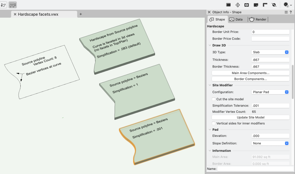
Ahhh! That's it!! @Tom W. - brilliant, as usual. For this Hardscape, the value defaulted to .083. Tried value of 1, which essentially eliminated all the curves and subbed in a single point. And decreasing values. .001 did the trick. The Edit Path window shows the orig source with the beziers intact. -B
-
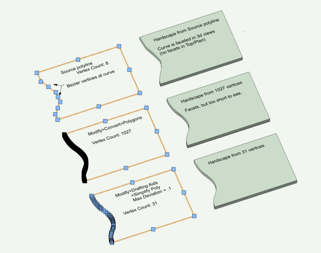
Hardscapes, and some other vwx objects, display faceted edges from smooth 2d source curves, eg bezier and spline. In the case of Hardscapes, Top Plan view does not show facets. But 3d views show a facet at each curve vertex. A workaround is to convert the source polyline (with curves) to a polygon. No curves, but probably lots of vertices which can slow down redraws and renders. Vertex count in this revised source can be reduced via Modify>Drafting Aids>Simplify Polys. Workaround is only a few steps, and helps the display at close zoom. But new edge is difficult to edit. Often easier to draw a new source polyline with bezier or spline points with subsequent and conversion and simplify. Big effort if lots of changes to several edges over design life. So save the original source poly! It might come in handy. Anyone have a better process? Example starts with 8 vertices. Convert to polygon produces 1027 vertices. Simplify Poly takes it down to 31. Facets nearly invisible at 31. But edits probalby best as do over. -B PS - this is not a 2d/3d conversion pref issue or render quality setting (both Very High), or layer raster resolution (300). Hardscape facets.vwx
-
Yes, sort of. The dragger remains, or reappears, if Mode changes from #4 to #1. But if mode is toggled from #1 to #2 (or #3), then back to #1, the dragger disapparates (nod to H. Potter & Co.) Still a bug, but can workaround easily. -B
-
This is a new mode for the selection tool, added in v2024. Change the mode in the Mode Bar of your Vwx interface - the modes are in the upper left corner of your screen. Choose instead one of the other modes by clicking one of the other 3 icons. I will get back to keyboard and offer an image, if others do not post before. -B
-
Zoom 3D screen image wrong after rotation
Benson Shaw replied to WhoCanDo's question in Troubleshooting
Zoom effect does not happen on my vwx2024 installation or MacOS system. I tested duplicate/drag/rotate CW/zoom in several views (front, top, iso) and several rotation via shortcut, Rotate tool, and Rotate 3d. Zoom via mouse wheel and shortcuts. Acts as expected. Sorry, no clue about your experience. -B -
Zoom 3D screen image wrong after rotation
Benson Shaw replied to WhoCanDo's question in Troubleshooting
Could this be a Far From Origin issue? The cursor x,y locator at lower right of your screen is hard for me to read, but seems to be in range of -21000,10000. or? If drawing units are feet, or meters, then that’s Far enough to cause problems. If units are mm, then not the issue. just an idea -B -
I’m becoming more frequently aware of “missing” features and capabilities in older tools and processes. This DAP is a likely example. Possibly unchanged since mcd? Users and developers realized that an option to preserve the source objects enhances the vwx experience, and the option was built in to new tools. The oft expressed desire to have tool and command updates is understandable. I often share it. I don’t know reasons for lack of such modernization, but I can think of a few possibilities, not all of them cynical: Update might break objects when porting between older and newer versions. Eg some rotation functions use positive values in clockwise direction, others in anti clockwise. Making all consistent could change rotation dependent objects when porting. Update time and expense conflicts with development of perceived or real need for new stuff. This involves long term planning, marketing, keeping up with competing products, etc. Old tools functions replaced by newer tools and strategies. Eg screen plane Specific workarounds are easy enough to discover and implement. Therefore complaints are limited. Eg the DAP - get in habit of duplicating source objects. Incremental improvements to newer functions take precedence. Eg slab, to aligned slab, to draped slab, concurrent with introduction of landscape area with components. . . lots more i can’t imagine I’m overall very happy with the constant improvements we do receive. But stand by for all my future gripes. -B
-
Creating a viewport from design layers
Benson Shaw replied to Monique Freese's topic in Architecture
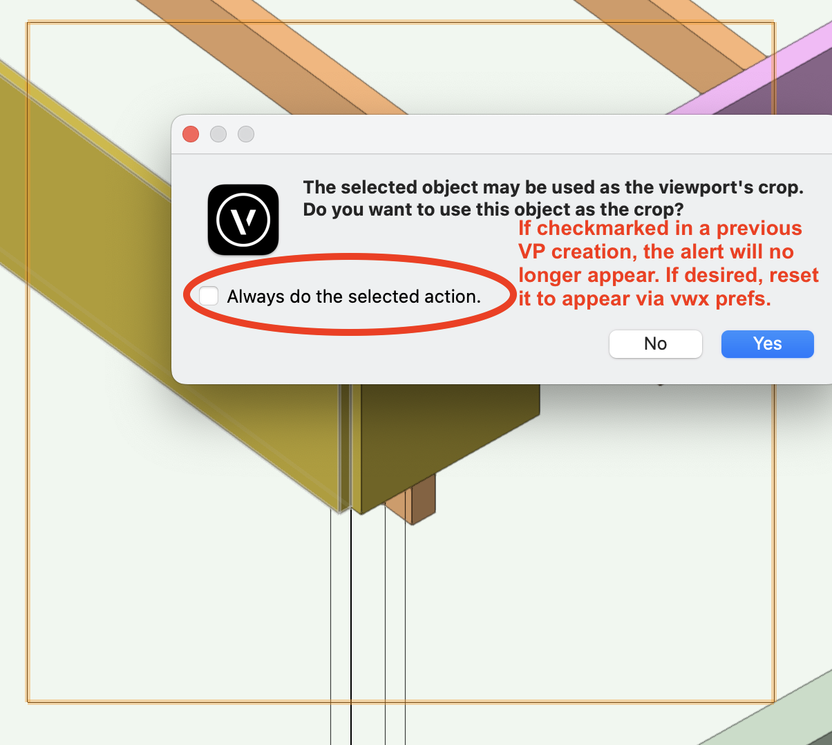
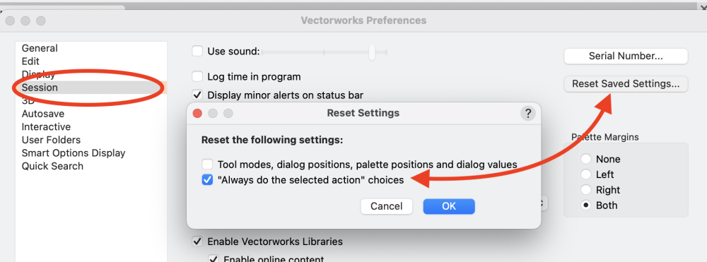
@Monique Freese The Alert notice might be missing because during a previous VP creation, you checked the "Always do the selected action" option. In this case, it would mean that the Alert would not appear. Instead, the Create VP dialog would appear. After closing the Create dialog, the VP will appear on the sheet as directed by the VP Create dialog. If this is the cause, and, for some reason, you want the Alert to appear, you need to reset the Vectorworks pref>Sessions>Reset saved settings. Note that this resets for ALL types of Always do warnings. No current way see a list and pick relevant items. -B
-
Creating a curved wall or extrude from a 2d elevation
Benson Shaw replied to Jim Dougherty's topic in Site Design
Try the Deform tool in Bend mode: Draw your skyline, eg on the layer plane. Then work on a duplicate of the skyline. Change the view away from Top, eg via flyover, or use iso. Select the duplicate . . . Rotate 3d 90° to stand it up on the x axis. (it's still a 2d object) Extrude it. Use negative value (extrudes away from view), or can be 0. Engage the Deform tool, set to Bend Solid > Symmetric mode Control bend amount visually, with guide objects on layer plane, or numeric by pressing tab for cursor fields. Make sure the protractor is on the layer plane. Some advantage to 0 extrusion for planning construction. Vertical frame posts and studs can be inserted, and will not have curved faces. -B Skyline bend(1).mov -
@mjsmithvt also check out these threads/posts regarding walls with slanted, canted, or otherwise shaped profiles, via insertion of a wall cut symbol: and -B
-
@Stephan Moenninghoff Brilliant! This two step process eluded me. Not sure I would have ever discovered that separate deforms on different planes is the answer. Many thanks for revealing. I tried on a couple generic solids made from extrusions of my 2d sample. One worked. Deform failed on the other. Some persistence may be required. -B
-
@Brandon Kleiman @Jeff Prince has it correctly re skewing 3d models similar to video in your link. Buuuht . . You might be able to get close with the shear tool. Only works on 2d objects, or groups of them. So, no PIOs for walls, windows, etc. End result is polylines, or group thereof, which can be extruded or otherwise modified. For scenery, perhaps this is enough for layout and fab work? -B Shear(1).mov
-
Artifact in a viewport, looks like a shadow, but from what?
Benson Shaw replied to unearthed's question in Troubleshooting
Thoughts To me, this looks like an artifact eg from a dwg/dxf imported or converted file. Especially an arc with associated fill back to its center. Object might have custom attributes rather than “by class”. I cannot explain the rounded corners. It might be a stray nested in a hybrid symbol (part of a former dwg block?), or in a group? The symbol/group extent is much larger than the shadow thing, so cannot be selected with marquee around the shadow. Try Select All and zoom to selection. Might be worth an old fashioned search via class shutoffs. Make a duplicate test file with a saved view to return to current state, then turn off half of the classes. If still visible, turn on that half and turn off the other half. If gone, turn on half of those, etc until the object’s class is isolated and the object can be found, selected, and interpreted. -B -
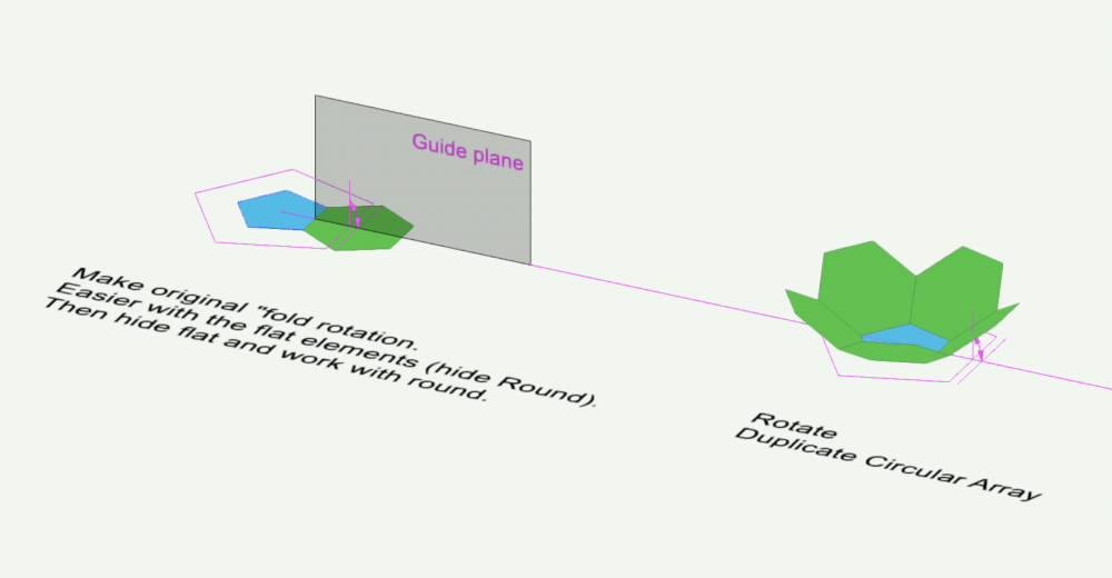
Wow! They take the edit away early. That shape with all pentagons is Dodecahedron, not Icosahedron. My bad (also didn't do well in Latin) -B.
-
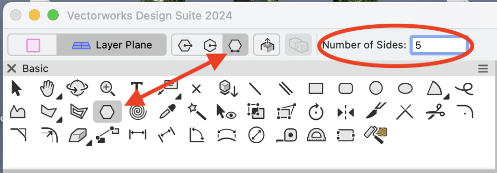
Soccer ball? or icosahedron? or? Do it by the geometry. Knowing the exact angle value is not needed. Use guide objects - loci, lines, arcs, planes. That 1st fold between pentagon and hexagon is the key. In this image copied from above, the big pink pentagon has edge length equal to the hexagon diameter (or if making icosahedron, fold is between 2 pentagons. Use the pentagon width for edge length of larger pink pentagon). Use the Regular Polygon tool in the Basic tool set. Set to 5 sides and edge mode. Click click across the hexagon (makes the guide pentagon). Center the new guide pentagon on the original pentagon. Rotate tool operates on that guide plane. Rotation (fold angle) is determined not by entering a value, but rather by snaps from start of the guide arc to end of the guide arc. -B
-
2d fasteners should not make such problems. If many 3d threaded fasteners are in the drawing, file size and slowing would be common experience when Show threads is implemented. Something that might help is to make each type/length of fastener into a symbol. Place instances of these symbols rather than individual fasteners of that type/length. Edit the symbol to Show/Hide the threads. Should save some redraw time and lower the file size. Another way to do this is to plan around the views. Maybe a fastener object is not needed in each location. Fasteners in views showing exposed threads, (Eg certain sections, or 3d sub assemblies, etc) choose Show threads. All others choose either a simple graphic (circle/hex for the head?)instead of a fastener object, or the fastener with hide threads. Symbols can work here, too. Make 2 symbols for each type/length of fastener. One version shows threads, the other does not. Use the Replace Symbol function in OIP to switch as needed in various views. Probably best to ungroup each fastener in its symbol so it has lower file weight because no PIO capability. This gets cumbersome, but still doable if not too many lengths of same fastener needed. Keep these dummy symbols in your Favorites library. hth -B
-
Flat glass roof with retractable panels
Benson Shaw replied to charlottesave's question in Troubleshooting
Not clear what/how should retract. A 3d flyover could help understand. Or add an image of existing similar product. or post your file. Is your pdf drawing a top view of a sloping roof, eg the center rectangle represents a ridge or valley? Are these intended to slide left to right into a stack, each panel independent and on its own track? (Weather tight could be an interesting problem) or do these independently slide up/down (paper direction) toward that ridge/valley? forum wants to help, but needs some detail. -B -
.las & .laz import problem with VWX 2023
Benson Shaw replied to Jeff Prince's topic in General Discussion
Will give it a whirl Monday or Tuesday. Thanks for suggestion. -B -
.las & .laz import problem with VWX 2023
Benson Shaw replied to Jeff Prince's topic in General Discussion
Not sure what this means? Can you elaborate? Maybe a Mac/Windows difference. I download LAZ, LAS, Shp from the NOAA Data Access Viewer>Elevation/Lidar: https://coast.noaa.gov/dataviewer/#/lidar/search/ For those not familiar Process is to marquee around the area of interest, Add to cart, go to cart, choose the file type and other parameters. Verify and complete the "order" (free - no charge). Return to viewer if desired - the marquee is preserved for entire session - order another format of the same area. Receive the data usually only after a few minutes. 3 emails per order - Order confirm, Link to the download, Order summary. Files are zipped, but decompress to folders containing the requested shp, laz or other, plus their support files. Shapefile contours import to vwx and georef reliably. LAZ and LAS generate a Corrupt File error in vwx and do not import/open. XYZ files import, but I'm finding their georef does not match the contours. Still toying with that. One zip with a LAZ attached. Can anyone open it? -B wa2016_pslc_king_Job978313.zip -
Dunno. Might be a way. You are probably aware, but just in case, one can hold down the spacebar and click any tool in any palette to replace Pan as the active temporary tool. This feature reverts to Pan at next access. I also would prefer default to Flyover (or other user choice) rather than Pan. -B
-
.las & .laz import problem with VWX 2023
Benson Shaw replied to Jeff Prince's topic in General Discussion
@Dave Donley Excellent! Currently, I am unable to open NOAA .laz files. They produce a Corrupt File error. I agree with @Jeff Prince - much appreciated whenever fix is implemented. Earlier would be even better. -B -
Interrupting action with rotate/move and continuing said action...
Benson Shaw replied to CaseyMarpa's topic in Site Design
Also, if the view can be set to see all hidden snap points as if the cube is clear, start your 3d poly on a visible face or edge or other snap point, press/hold the b key (activates the xray mode which allows access to surfaces and snaps beyond the “front” surfaces) hover/acquire/click the next snap point, continue holding the b key and hover/acquire/the next point, etc. Might still require the Flyover as described above for some of the snaps. AWK now, so not tested, but I think this old school approach works. Draw separate polys on the separate faces, rotate view as needed each time. Cut the cube to clipboard, or move it, eg to another layer, Select all the segments, Compose, replace the cube. -B -
It’s a super handy feature, but . . . When using the Edit VP option for Add Reference Crop Object, remember that the option remains checked next time the Edit dialog is opened. As long as the option is enabled, a green rectangle will be added to the design layer EVERY time a design layer is accessed via the Edit Viewport dialog. Result can be a bunch rectangles from different VPs which may then be visible in other viewports and likely need deletion. Or, a stack of rectangles will accumulate from repeated access via same VP. Delete one, and the rest of the stack remains, which can seem like the delete failed. Suggest be aware, or better, open the dialog again and uncheck the option until needed again. -B