Benson Shaw
-
Posts
4,322 -
Joined
-
Last visited
Content Type
Profiles
Forums
Events
Articles
Marionette
Store
Everything posted by Benson Shaw
-
@Dave Donley can you elaborate a bit on the 5 meter limit? And whether it is helpful to place objects or points of known size and separation in the scene? Traffic cones, tape “x”s, etc
-
Can you post a vwx file exhibiting the problems? That’s best for troubleshooting. -B
-
Setting to Change Dimensions form Feet & Inches-to-inches Only?
Benson Shaw replied to CW2020's topic in Architecture
Hoping, too much, I think, for this control without using the Dual standard. It’s a longstanding gripe on these forums. But, I think you can achieve your goal with a simple adjustment In a dual dimension’s OIP you have choice to show both dim modes (side by side or over/under), primary only, or secondary only. Sounds like you have pref for Both, which shows feet&inches plus, in brackets, inches (ya know, dual). In the OIP dropdown, choose instead the show Secondary only. This disables/hides the Inches&Feet (primary) part. If you made the conversion for the selection, and all your dims show both modes, select all of them again, and change the OIP pref so that only the secondary (Inches) is displayed. Or did i miss your intent? -B -
Setting to Change Dimensions form Feet & Inches-to-inches Only?
Benson Shaw replied to CW2020's topic in Architecture
Several things control this. 1. If you want ALL standard dims in the drawing converted to inches only (or to any of the other options): Open the File Menu>Document Settings>Units In the resulting Units Dialog, choose Dimensions (top item) from list on the left side. Near top, click the Units dropdown menu and choose Inches from the list. Result will be conversion of all standard (not dual - see below) dimensions in the drawing. 2. If you want to change a selection of dims to Inches and leave others as Feet and Inches, you need to set up and apply Dual Dimensions (bit of a slog, but you will get there): First - Set up Dual Dimensions for the drawing as follows: Open the File Menu>Document Settings>Units In the resulting Units Dialog, choose Dual Dimensions (2nd item down) from list on the left side. Open the Units dropdown (I think it defaults to mm) and choose Inches. Adjust your rounding preferences as desired. Click OK to accept. Can be edited later. Sorry, “dual” is as high as it goes. No option for triple other multi dim combos) Next - In the drawing, select the dims you want to change. In the OIP>Units menu (near top)> choose either of the Dual Dimensions options (Stacked or Side by Side). Further down in the OIP>Dual View menu>choose Secondary Only (defaults to Both) Below that click the Sec button (secondary dim) and adjust precision fields as desired. The selected dims respond to the new pref. OK, post back as needed. -B -
Hard to say from the image. but . . . A blue/cyan line kind of weaves in and out of your terrain. If that is a Grade Limits object, which often displays as cyan, you might benefit from deleting the complicated shape and redrawing as a rectangle surrounding the terrain boundary, or even to enclose all the other objects which extend beyond the terrain (crop?) boundary. Assign to existing. Update the terrain. Good luck! Post the file if possible. -B
-
Did the construction business stopped using Nails ??
Benson Shaw replied to FBernardo's topic in General Discussion
Fasteners is a vast subject. In a way, I don't blame vwx for incomplete options. Its rather a fools errand for vwx to try to include EVERYTHING in every size, past present and future, from all manufacturers (there are slight differences). But in another way, I think a more nimble PIO is called for. I keep a favorites file for fastener objects I’ve modeled. Many forum threads discuss fastener modeling. Shows the need to improve. Nails? At least add a few of the basics - standard and finish heads in several sizes for US and metric. The prominence of nail guns in stick construction indicates need for clipped head versions. Screws? Add bugle heads? Torx drive? Bolts and Machine Screw systems? Add Couple nuts, Nyloks, truss head, Drive options (slot, cross, square, hex, torx, even some of the “security” options, Threaded rod, various concrete and earth anchors. Cable clamps and stops? Thimbles? Turnbuckles? Hose clamps? I think at minimum, update the PIOs (annually?) with addition of at least one or two of the currently evolved construction industry fastener iterations. The tools would become more effective over time. Another option would be user input/customization option in one or more of the fastener PIOs. A blank template to accept user geometry and associated data with scaling built in for the various sizes. A crowd sourced library? -B -
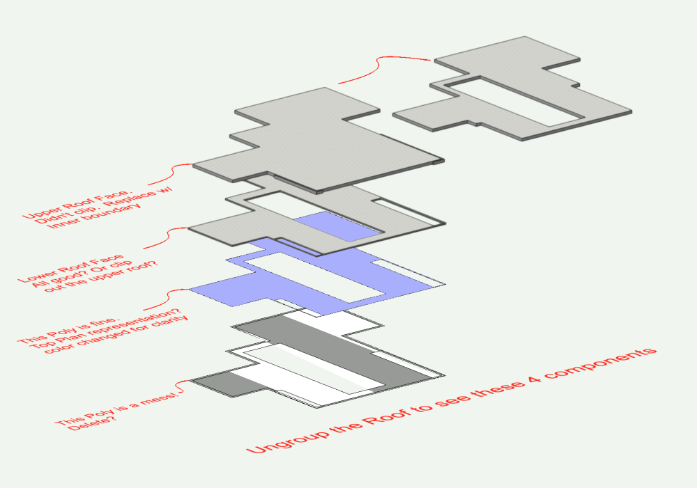
@AlanW I see now that the roof is developed using an edge offset (-1'0") for the top component. The top/plan roof graphic is fine with 0 offset. But a negative offset makes those partial fills. Could you elaborate on how to remove (or contain them in the poly) those fills in Top/Plan and retain the textures in 3d? Thanks! -B
-
Ungroup the roof (well, a copy) to see problems with the components. Click through the layers in the revised file. 2d source poly has a corrupt duplicate. Delete? Upper roof face did not clip at the corner penetrations. Edit the poly>Inner Boundary Tool>Delete original poly. This only addresses the 2d graphic problem. My product produces a stack of roof faces. I don't know enough about roof creation to add that upper component while creating a roof object. Lower roof face probably should be clipped again at perimeter of upper? -B roof - fill v2.vwx
-
Another way is to use Image Fill on a 2d object. Apply the image by choosing Image in the Attributes Palette Fill pull down menu. Adjust the size and rotation of the image via the Attributes Mapping tool. -B

-
The wall fit to objects dialog includes an interval parameter for round walls. Data value seems be numeric rather than unit? So what is meaning of the interval? Vwx HELP only identifies this as the increment. Neither term is explained or illustrated, nor is there indication of effect of higher or lower values vs 0. Is this the number of points made with even division of the round wall length? Or a length of the segment between fit vertices? Or? My tests with adjusting the interval number when fitting a round wall to stepped geometry above either fail or fail worse depending on value in the interval field. Solution is to revert to manually adding wall peaks? -B
-
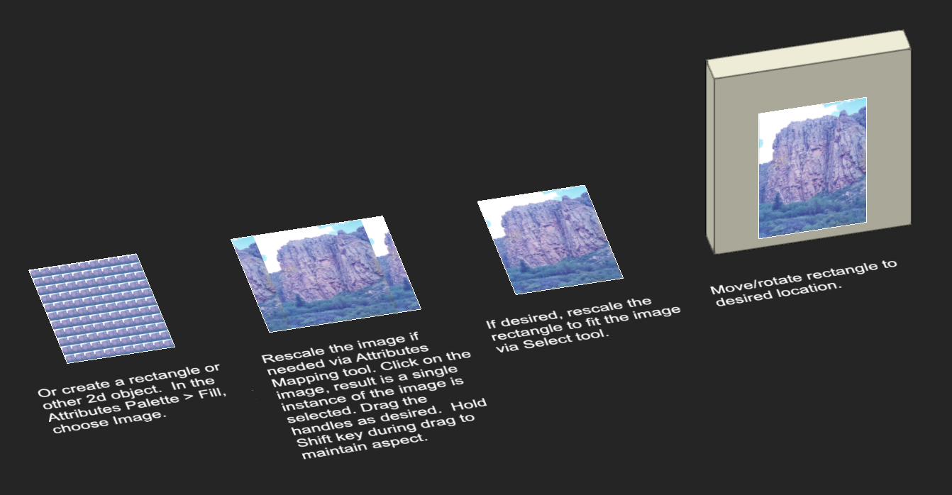
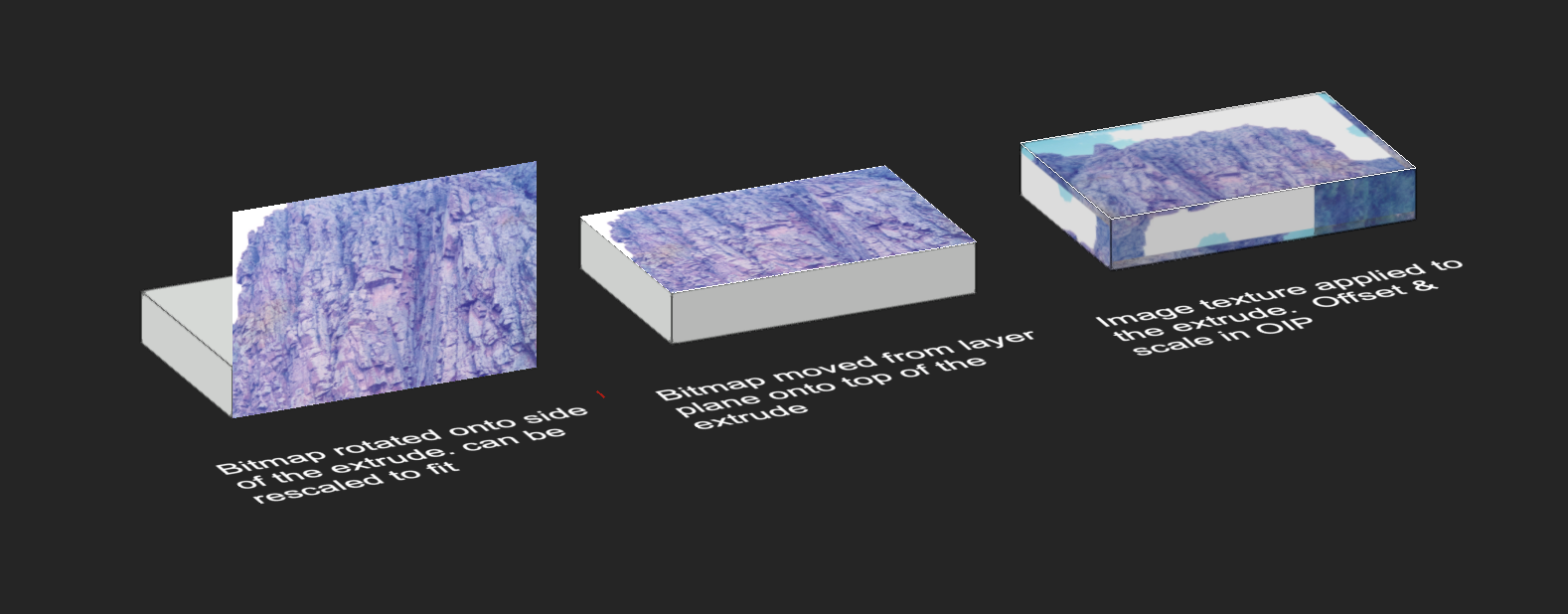
A couple things can work. A. Create and apply a new image texture: The extrude is a 3d object. Images are applied to 3d objects as image textures. Textures apply only if the 3d object has a solid fill (white or other color). Textures, including image textures, are resources available in the Resource Manager. Create a new image resource and image texture as follows: Open the Resource Manager. In the file list (upper left side), select the currently active file. It may already be selected, especially if only one vwx file is open. Click the New Resource button at bottom left side. This opens a dialog with list of resource types. In the dialog choose Renderworks Texture. If no image resources are present a file browser window opens. Navigate/select your image file (which then becomes an image resource in the vwx file). If image resources are already present, a dialog opens offering choice to import a new or to access list of existing image resources. In appropriate dialog, navigate and select the desired image. The Edit Texture dialog opens. Name the new texture (upper left data field) Click to open the Color shader menu. Choose Image A dialog with this file's image resources opens. Choose your image, and close the color shader menu. The other edit functions can be adjusted to suit, but too much to explain here. Accept defaults and click OK. Now you have an image texture in your file. In the drawing area, select your extrude. In the OIP>Render tab, Click the Texture button. Choose Texture. In the dialog, choose your new texture. Or you can assign textures By Class. (Make a new class with this texture selected in the Texture tab. Assign this new class to your extrude). This puts the texture on all faces of the extrude. Render the drawing, eg Shaded. Whew! Bunch of steps, but textures are a deep topic and this just grazed the surface. or B. Use the image as a 2d item placed on a face of the extrude. Paste your image into your drawing area. OIP identifies it as a Bitmap. It's on the layer plane. Drag the corners to approx desired size. In a flyover view, use the Move by Points tool to move a corner of the image onto corresponding corner of the extrude. If needed, this can move the bitmap up/down along z axis If need to rotate onto a vertical face of the extrude, use the Modify>Rotate>Rotate 3d command to turn it vertical, or place drawing in side view and rotate the bitmap 90°, or, apply the Rotate tool with drawing in Automatic Plane. Use the extrude vertical face to guide the plane of rotation. If needed, Move again (I like Move by Points) and/or Scale again by dragging corners. Bitmap is a separate object, not part of the extrude. If needed, group the Bitmap and the Extrude so they move as an assembly. Note, the bitmap will be visible from both sides, unless obscured by other objects, and the image will be visible in rendered and wireframe views. If the extrude color fill interferes with the image, move the image slightly away from the extrude. Post back if more help needed. -B

-
Vectorworks abandoning perpetual licences
Benson Shaw replied to line-weight's topic in General Discussion
Correct, in the sense that it could become unsustainably expensive. If switching to other software, best to select all the vwx files and batch export to, um ???, the most mutually compatible file format. Determining that best format is huge problem - moving from familiar software to something only minimally tested, and then hoping to depend on imported geometry and data - yi yi yi! But if intermittent access is available, and I finally settled on another software after my license lapsed, I could pay the monthly fee one time to access and export any vwx files. A literally unfortunate exit fee. This is non optimal workaround, but at least can provide a basis for continuing work. I am trying to imagine a strategies for those who find this untenable. -B -
Vectorworks abandoning perpetual licences
Benson Shaw replied to line-weight's topic in General Discussion
Not clear about this, but maybe?, one could jump in and out of the subscription for vwx. Not so great if only needed for a minute, because higher cost (annual/10 ?). But at least this would provide intermittent access to work with vwx files after an annual license lapses: ". . . We also offer monthly and annual subscriptions. Monthly subscriptions are perfect for project-based customers, flexible staffing needs, cash-flow sensitive customers, or trying out new products. Your monthly subscription will automatically renew each month, but you have the flexibility to cancel up to four (4) days before your renewal date to avoid being charged in the next billing cycle . . ." -
Psychedelic fence object strangeness - screen grab attached
Benson Shaw replied to hollister design Studio's question in Troubleshooting
Paste fence into blank file to test? Near origin? Or stray object far from origin? Service pack update? Post the file? You are on a roll here with stuff going bad! -B -
@hollister design Studio I have seen something similar, but in simpler file. Switching the LA to 3d Poly Instead of Texture Bed made the terrain maintain its own texture. But, this is probably more of a workaround than a solution. Your idea that conflicting site mods is cause has some merit. I tried shrinking the LA. Just a little offset did not resolve. But shrinking to 75% or so made things behave. Obviously not a workable process, but illustrated a potential cause. Ultimately I could not track it further and went for the 3D poly mode. That said, I’m not sure why the Tbed is important when the poly mode accepts the texture. Difference seems to be only that the 2D representation provides a fill. Or? -B
-
How can I create a Viewport of a symbol?
Benson Shaw replied to Bruce Kieffer's topic in General Discussion
Some other approaches, not necessarily better, but might serve in different ways: 1. In the symbol definition, add dimension objects. Create a special dims class just for these "internal" dims in the symbol definition, eg duplicate the default Dims class and rename Dims-SymbolDef or other descriptor. Hide the special dims class except as needed in any dims VPs. Use the Automatic plane mode to create the 3d dims, and the 2d mode to create the hybrid plan/front/side view dims. (or skip the 2d's and take care of those in the dims VPs). Place an instance of this symbol on the parts dimension layer. Direct the Worksheet to exclude the dimensioning layer and any VPs made to illustrate the symbol dimensions. These dimensioned symbols can be added as resources to other files. Some Downsides: 3d dims do not rotate to camera, so have limited effective view/camera angle This makes the symbol definition slightly "heavier", which might affect performance if many instances are placed in Design Layers. 2. Duplicate the symbol definition. Use only in dimensioning layers and vps. Name it Symbol#1_Dims, or other descriptor. It can have a special class if needed. If there are multiple symbol definitions duplicated for dimensions, they can all assign to this same class. Add Dimensions to the symbol definition as above. Place an instance of this new symbol on the parts dimension layer. Direct the Worksheet to exclude the layer and various special classes of this special dimensioning symbol. Some Downsides: This symbol definition will need updates to match any changes to the original. Copy/Paste from original, then redimension? Manage the new classes in VPs and worksheets. 3. Place a symbol instance (the regular, original symbol) on the parts dimension layer. Convert to Group so it is no longer counted as the symbol in the data sets. Inside the group add 2d or 3d dims which can show/hide in the various VPs. Group can be switched to a special class as needed for visibiliy control. Can use special dims class or default dims class, depending on needs. -B -
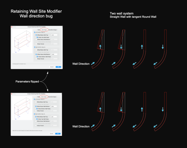
Retaining Wall Site Modifier - bug #1 ? - Source Wall direction
Benson Shaw replied to Benson Shaw's topic in Site Design
@bgoff, @Tamsin Slatter Is this known? or non issue? Filing bug for this and the "hook" in the curved wall. -B -
Locus points on things like drape, projection, etc
Benson Shaw replied to Speedo44's question in Troubleshooting
Thanks, Pat - Auto switching is disabled, power adaptor plugged in. I see the green bars again while logged in, and refreshed. Wondering if anyone else ever sees this. -B -
Locus points on things like drape, projection, etc
Benson Shaw replied to Speedo44's question in Troubleshooting
Oh! They disappeared. Some redraw must take care of it. I logged off, back in, and here are the bars again. -B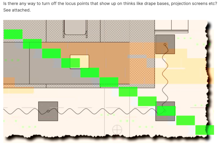
-
Locus points on things like drape, projection, etc
Benson Shaw replied to Speedo44's question in Troubleshooting
Side issue: Does anyone know source of those big green bars in top image? Or, does anyone else even see them? I get them sometimes from scans, or website image. Or, they display on one device, but not on another, or in different software on same device. Just curious. Thanks -B -
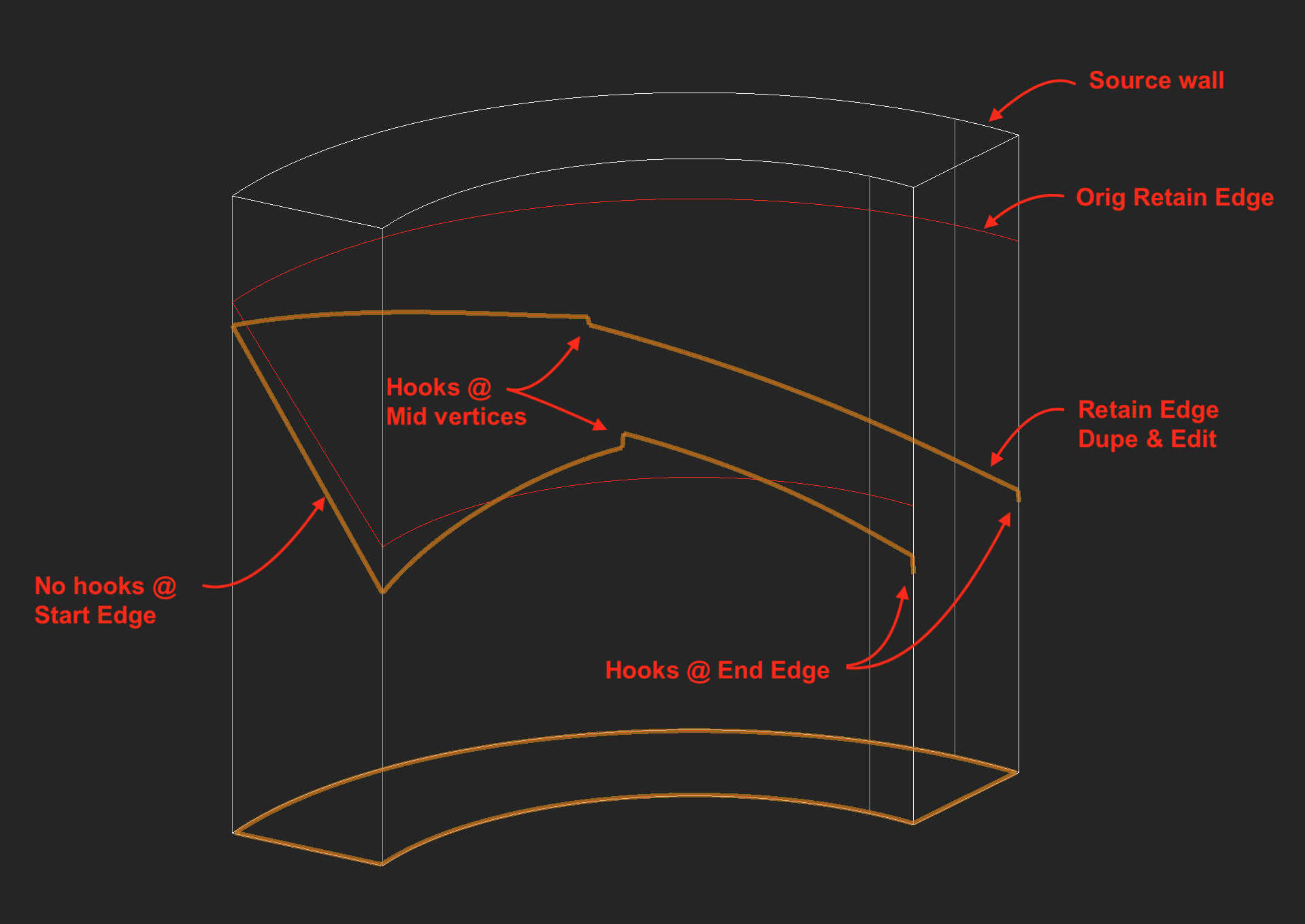
Another Retaining Wall Site Modifier quirk: Create the modifier from a Round (arc) source wall via AEC>Terrain>Create Retaining Wall Site Modifier. Edit the z value at center or end of Left/Right Retaining edges via Reshape tool. Result is a hook, or added short vertical (nearly) segment at the new position. This hook does not have an editable vertex. But it does cause a crease in the site model surface. Strangely, no hooks at start edge if those vertices are moved. In the image, the End edge is hidden for clarity. -B

-
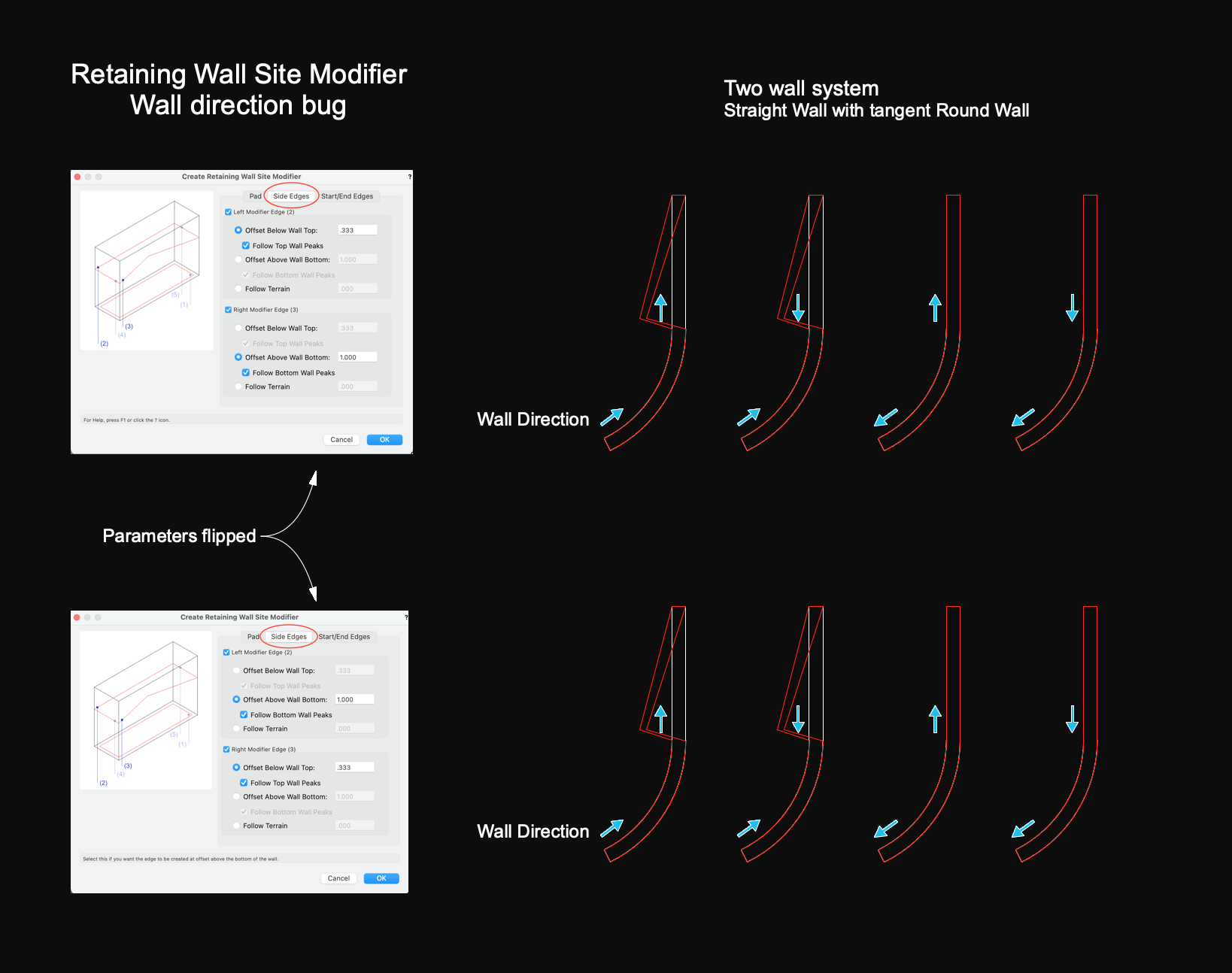
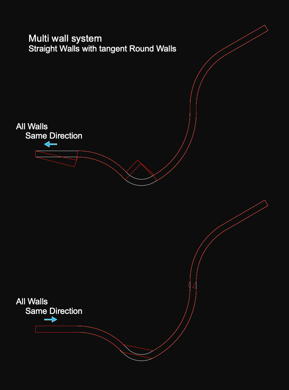
Working with the command AEC>Terrain>Create Retaining Wall Site Modifier, and finding quirks. v2022 file attached Source wall directions determine high/low retaining sides. But some combinations of wall direction produce retainage boundaries jogged out of wall alignment, shown here in Top/Plan. This added kink cannot be corrected via the edit tools. Certain source wall direction combinations produce proper retain alignments in a 2 wall system. I find it difficult to predict which combo will produce correct alignment and correct high/low sides. Multi wall systems may not have a combo that works. Workaround is to apply the command to individual wall sections. -B Retaining Wall Site Mod.vwx
-
Ok, different kind of screen share problem. MBP, vwx tabbed application interface, no external monitor, so all the zoom interface palettes and widgets have to park somewhere. The Zoom screenshare palette defaults to top of screen which hides part of the view and mode bars. So, move it to bottom of screen. Uh oh! Some of the tool dialogs extend full height of screen. In one recent session I could not complete a tool task because the vwx blue OK button was missing. I didn’t understand that the Zoom screenshare palette obscured the entire lower part of that dialog. Also didn’t think to use the Return key. Fortunately another viewer figured out my plight and prompted me. Moved the bottom the vwx interface upwards, so Zoom could fit below. I don't see the slowdowns so much, but the MBP fans always get a real workout. Can help to shut off the zoom camera/video during the share. But then need to remember to switch on again at end of share. Or come up for air once in a while to take off some heat. -B
-
Navigating from viewport to design layer goes to wrong position
Benson Shaw replied to Konnie's question in Troubleshooting
This Vectorworks Pref might be involved: Center on Objects after view change -B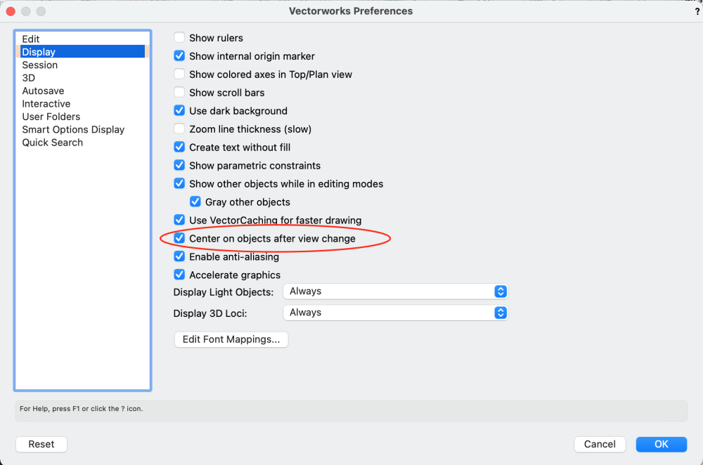
-
Just an opinion: Although Landscape Area can have components, they seem slow to redraw on my old system, especially if a tapered component is in the mix. My preferred approach for this would be to use the site model (DTM) as the substrate/filler of the mound and use a Landscape Area with components, eg a surface material and porous concrete base or whatever the section demands. Similar to construction layers. In this case, I think the DTM mound profile should be shrunk so that the LA components sit atop (LA component datum set to bottom of lowest component), thereby adding thickness to attain finish grade. An alternate approach is to contour the DTM at finish grade, and “sink” the LA into the mound (LA component datum set to top of uppermost component), thereby excavating the DTM. -B