Benson Shaw
-
Posts
4,368 -
Joined
-
Last visited


.thumb.jpeg.48a6fdc44e48c98b8e1b507e86e57e95.jpeg)
-
Not sure this solves or even helps, but another approach is to make a Vp of the whole area (regular VP, not a section vp, with clip cube if needed), then make a crop with breakline shape on the section line edge. Duplicate the vp and mirror the crop, or create a new one with break shape on opposite edge. I do this to represent segments of vertical poles and other elements. I think the section line can be associated to both vps, but not sure. -B
-
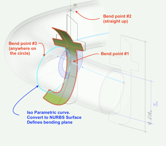
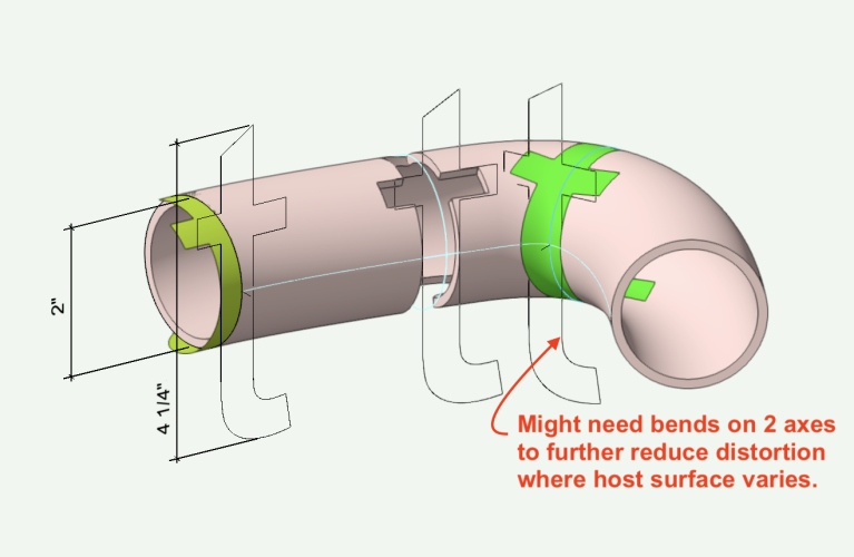
Wanted to extend Paul's good work here. These methods introduce a bit of distortion, when projecting the text or other object straight (extrude) onto the curved surface. As the text size approaches the host surface diameter, the distortion increases. Taller than the host ruins the projection. For less distortion for tall text, convert the text to NURBS Surface and bend to near the surface. Then, shell the bent item through the surface and intersect or section to make the shape cut onto or through the surface. If the host changes radically, multiple bends on 2 or more axes can help reduce distortion. Another way is to create an image texture and apply it to the host. Then place 3d loci at significant points, remove the texture, connect the dots with NURBS curve, convert to NURBS surface, shell as needed for the intersection. This is not distortion free, and is a real pain to do. Probably not worth the effort, but wanted to add to the conversation. -B
-
No, export to Revit seems to have only the options for project (rtv), family (rfa), or all (.). Import rtv to vwx has the options to include textures and materials, but that didn't work in my case. Does anyone have a way to force the texture export? -B
-
I have a model with several image texture surfaces. Export to Revit then test via reimport to vwx with the Textures and Materials option enabled. No textures. None of the classes survived the export/import process either. Any workflow tips to get the textures into the rtv file? -B
-

Rotation Query - Rotation cause twisting of Object
Benson Shaw replied to Michael Siggers's topic in General Discussion

-
Rotation Query - Rotation cause twisting of Object
Benson Shaw replied to Michael Siggers's topic in General Discussion
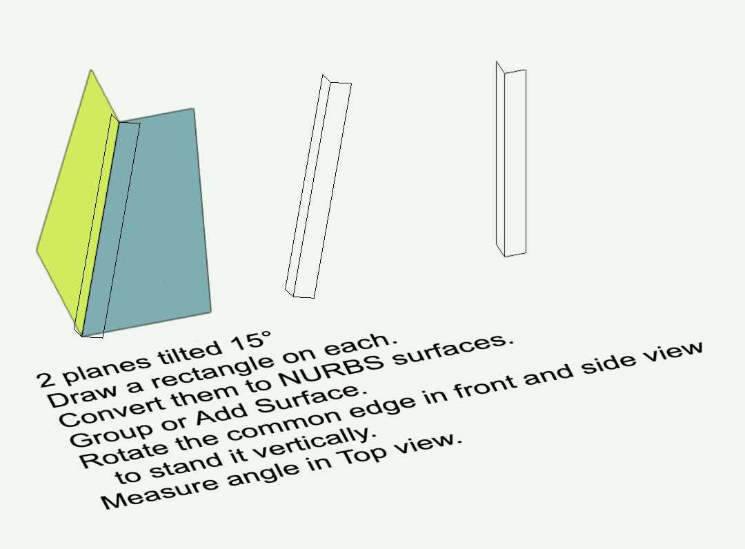
Hi, all Two items 1. I would use different words. The 40x40 is not twisted (eg twist to wring out a washcloth). Yes, it is rotated, which explains view displaying edges with some separation. Also, it will never fit flat against both sides of the hood. 2. The planes of the hood, tilting from 2 directions, do not meet at a right angle, They intersect the layer plane at 90°, but plane to plane angle is greater than 90. Think about a really flat pyramid. Adjacent planes rise a bit from a square base, but the apex is almost on same plane as the base. Now flatten it all the way - angle between the planes is 180° (they are co planar). An infinitely tall pyramid will have adjacent planes approaching 90°. Face/face angle for other rises is between 90° and 180°. A pyramid face to face angle is 93.84° if both sides tilt 15°. Resaw or machine the 40x40 to fit against both "faces". Eg slice 1.92° from 2 adjacent faces of the 40x40. hth -B -
Not clear which pieces are “connection pieces” Is the problem cutting the tongues? One technique: A. Cut all the grooved pieces as usual B. Cut first side of tongue edges (eg half depth). Then through cut the perimeter to separate the part. C. Cut a jig (a shaped hole) to accept the tongue pieces, or several jigs. D. Register the jig location (or just anchor it in place), and create a path for just the tongue edges. E. Place a tongue piece (from step B) face down in the jig, and cut only the edges needing 2nd side of tongue. Also consider half tongue. Or tab and slot. Needs some overcut to “square “ the corners, but can be quite tight and invisible joints. HTH -B
-
Also, @JunoA. Welcome to the forum! -B
-
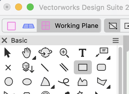
@JunoA. Your second screenshot shows that you made a working plane on that tilted surface or were about to make one - you need to click somewhere on the highlighted face. Next step is to disengage the Working Plane tool by selecting another tool, eg the rectangle tool or other 2d or 3d object making tool, and draw objects with that tool. If you keep the Working Plane tool active in the Planar Face mode after you establish a working plane, your next click will disable the one just created and make a new working plane. In your third screenshot it looks like you did not choose another tool, but instead clicked on the layer plane with the Working Plane tool. That click cancelled the WP on the tilted surface and made a new WP on the layer plane. Note that when a working plane is established (the pink rectangle is present) the mode bar plane indicator (upper left corner of the vwx window) will be greyed out until a drawing tool is selected, at which time Vectorworks will automatically enable/indicate the Working Plane mode for that tool. Also note that while the Working Plane tool is very useful, but a newer function, the Auto Plane mode, can streamline the workflow for many object making tools. Activate via the little pink square icon in the mode bar. Engage a tool, click the Auto Plane icon and hover on a face where you wish to create an object. Click to start the object and it will map onto that highlit face. No need to make a working plane. If desired, click the Layer Plane icon in the mode bar to create objects on the layer plane. hth -B
-
Benson Shaw changed their profile photo
-
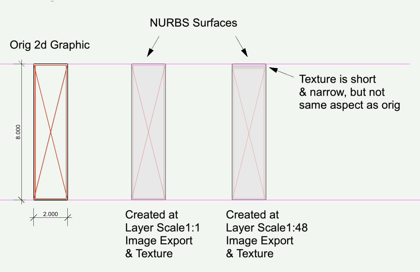
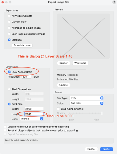
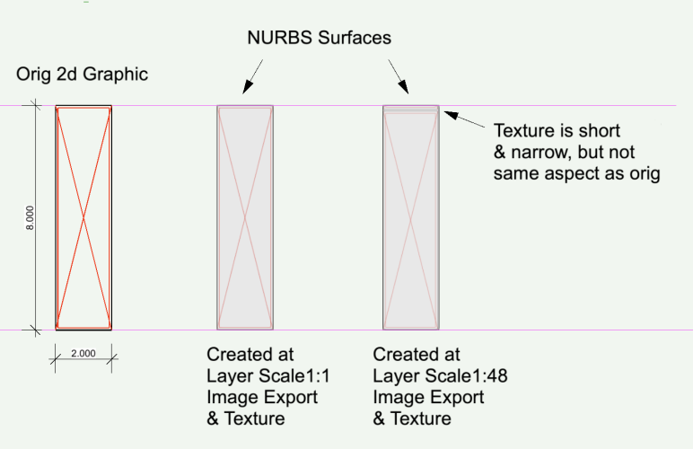
Found that image export size is inconsistent at different layer scale. Bug? Goal is to export image of a line drawing for use as texture (not repeating) and as file for printing Silicone Edge Gasket fabric printed with image for backlit signage). Success if drawing layer set to 1:1. Image Export dialog correctly displays dims to match scale of graphic. Fail if change layer to eg 1:48. Image Export dialog shows incorrect width/length ratio, and the export matches the incorrect ratio. Fail @1:48 if adjust the ratio in export dialog (uncheck the Lock Ratio) - that only changes space between image repeats. Fail if try to adjust the OIP Render texture scale - Texture is not same aspect as original. Workaround is always use 1:1, but Why??? Test this in attached vwx2024 or a new blank file. Do an image export and create an image texture at 1:1, then another with layer scale changed to 1:48 -B ImgExport @ Scale.vwx
-
Nomad App - Room Plan mode - rotation about Z
Benson Shaw replied to zoomer's question in Troubleshooting
Lost? Sleepless? you never know. Whoa! Cool look. But circulation is difficult. Build, too. -B -
Nomad App - Room Plan mode - rotation about Z
Benson Shaw replied to zoomer's question in Troubleshooting
ok, as you suggest, never mind the mag vs true north idea. Internet lookup shows declination in Seattle (USA) about 15 deg east, Berlin (Deu) about 5 deg east, and Faroe Islands (FRO/DNK) about 3 deg west. Not certain of your location, but these declinations are not similar to your 30 deg rotation. B -
@izaac welcome to the forum! Suggest you make a signature to show your vwx and OS info in forum account settings. -B
-
Nomad App - Room Plan mode - rotation about Z
Benson Shaw replied to zoomer's question in Troubleshooting
Zoomer, sorry, if some or all of this is not relevant. I'm adding questions and speculation, because I don't know. Does Nomad apply GIS location? I think GIS systems deploy top of map as True North (Geographic North) rather than Magnetic North. Or? Or maybe GIS/Nomad uses Grid North (Meridians are straight and vertical on the page)? Could one correct the Nomad rotation with field data? Eg use a compass on site (Mag North) to note alignment of a wall or other component in or near the scan. Then rotate the scan to match? Or maybe compare the scan to local GIS maps and rotate to match? If drawing alignment to True North is needed, apply the current declination data? Regarding North in general - I think modern electronic survey equipment applies, or translates to, True North according to local CRS. Designers often create a Project North for graphic convenience - eg page sides are parallel to a curb line or property edge that seems "close enough" to be called "North". But then the official survey sheet in the drawing set is aligned differently. Could some portion of the Nomad rotation be result of declination between Magnetic and True north or Grid North? I think CRS choice also affects North direction. Is the commonly used WGS 84 dependable for North? (Google maps?) I think further from equator makes more distortion. USA has 2 or 3 basic CRS choices for many states (eg north or south portion of the state) and those choices have historic as well as updated versions plus more versions for the measurement system applied (Foot, Survey Foot, Meter). These CRS could present differently in drawings, including rotation. Yi, yi, yi, the Survey foot (US Foot)! US is supposed to have abandoned the Survey Foot and adopted the Foot (International Foot), but we still depend on the huge library of old surveys made with the Survey Foot. - no significant difference between survey foot and tape measure foot in a small lot project, but regional transit systems, road networks, waterways, state and national boundaries, etc need attention to such differences. Metric please! OK, enough. -B -
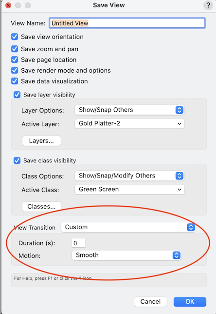
Yes! I add 3d loci for target(s). Class them so can hide for movie saves. At least it works with snapping for the manual aiming method as long as view is orthogonal. I found no snapping or cross hairs or other aiming aids for the walkthrough tool method in Camera View. But the loci would be visible if the class is not hidden. The Saved View animation is still pretty good especially by applying the duration and motion options near bottom of the Saved View dialog. These with the OIP key frame duration controls kinda take the place of that old interface with the sliding graphic. I did like that one, but think that has phased out. Or is it still there somewhere? I have not found any option for the Look To Selection you mention. I suppose one could select the object, the zoom to selection, then save view. The object could be a camera aspect rectangle scaled and centered in the view to create the desired scene (workaround city!) I find working with these view tran is a bit unpredictable. I have not figured out what controls the flight path between views. It may follow an arc when a straight line is expected. But results can be quite pleasing. -B