
Katarina Ollikainen
-
Posts
365 -
Joined
-
Last visited


.thumb.jpeg.48a6fdc44e48c98b8e1b507e86e57e95.jpeg)


-
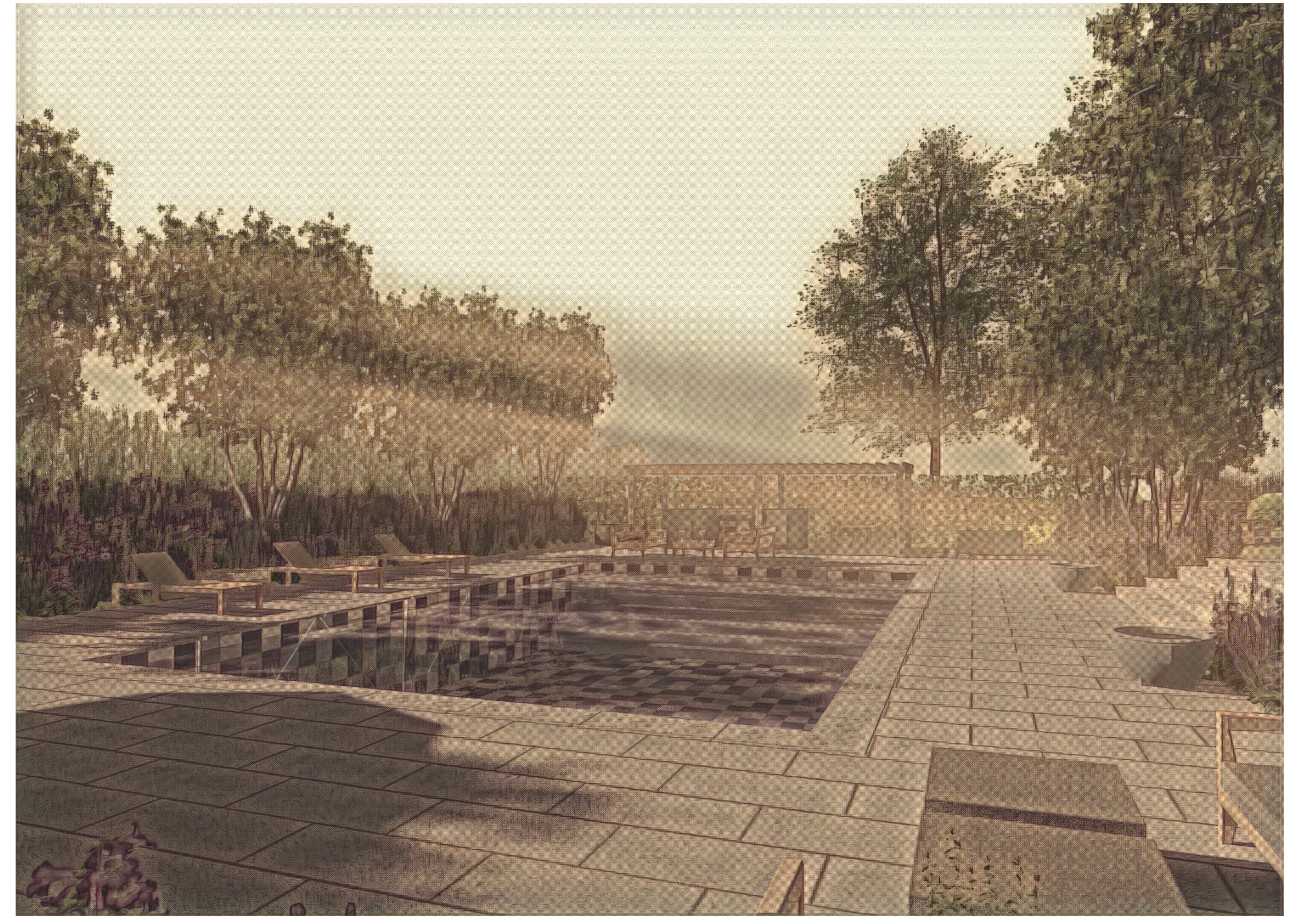
@Daniel OKane, can you explain the issue in more detail? If I take the contours you have here, convert them to 3D Polys (as they are simply lines in a 3D plane right now), ungroup them and then create the site model, I get the site model below. In the file attached, I can see some extra geometry along the edge of the site model. I've filed a Jira to see why this happens. For now, you can just crop the site model slightly, and it will be invisible. Site model created.vwx
-
@whitwam, I've looked at your file and filed a bug on it. There is a slight discrepancy with the polyline path when converted to a hardscape (it has to do with the simplification tolerance). To proceed, I suggest you trace the hardscape with the polyline tool and then convert it to a hardscape. I did this, and the issue went away. (I also tried to ungroup your hardscape and recreate it from the polyline that way, but that didn't work.) Let me know if you still have issues with the file after this. Going forward, we'll examine these cases and try to find a way to deal with them internally so they don't interfere with the model.
-
Hi @whitwam, can you please post the file so we can take a look.
-
 @hollister design Studio, Yes, it's already booked in. It will be @Tony Kostreski who runs it, I believe.
 -
@Ben Miura, Can you please post a sample file with the result you get - I'm not sure where the OK shows up for you. Also, I would recommend using the data tag for the plant instead of the built-in tag, as you'll have more control over it.
-
@hollister design Studio, I've opened a Jira to see what's going on here. At first glance, I can see that the plants behave better when I create a style of the unstyled LA, but this shouldn't be a requirement. I'll keep you updated on what we find.
-
@Rebecca R, can you please send me a sample of your excel sheet/txt file so I can see how it's set up?
-
Hi Katarina..
I am trying to create a Site model section...but the result I get is no color distinction between existing and proposed terrain...all the lines are black....Is there something that I am missing...???....Thank you
-
Oh, and if you're using Architect instead of Landmark, the command is under AEC>Terrain>Site Model from Source Data
-
@Tom W. - Ah, yes you're right! I'm behind on the fixes 😀
-
@AcetoLAare still having, Hi, please see the recording. Let me know if you still have issues. Creating a site model from nice data like this will only take seconds. Creating site model.mp4
-
@TeeMuki, If you share the vwx file and one of the files you're importing, I'll have a look - you can send them directly to me if you prefer. But first, have you georeferenced the layers as well as the file?
-
Default Plant Record disappearing
Katarina Ollikainen replied to Carol Reznor's topic in Site Design
Hi @Carol Reznor, can you please elaborate - which record disappears? Is it the PlantMaster record? -
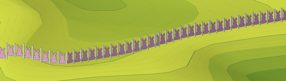
@Dan Johnson, In the image below, I've just extruded a shape, converted it to a symbol, and then used it as a fence panel (I have to admit, I might have been inspired by the season - I don't expect anyone to build a fence like that). The point is that your fence panels can look however you like. If you want to work with rails, there are a few more parameters to consider, but you have enormous freedom there as well.