TomKen
-
Posts
228 -
Joined
-
Last visited
Content Type
Profiles
Forums
Events
Articles
Marionette
Store
Everything posted by TomKen
-
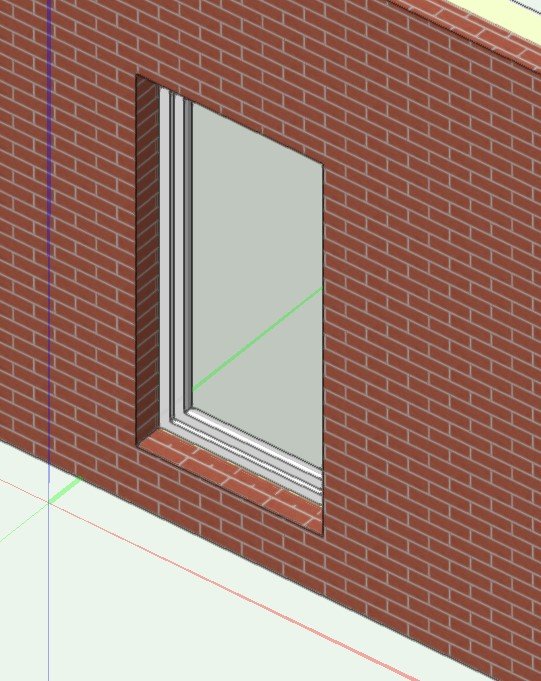
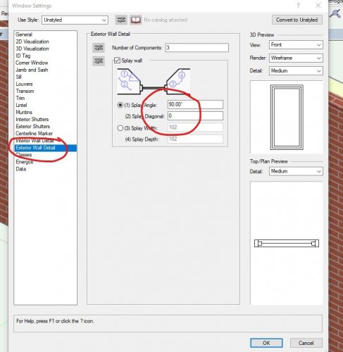
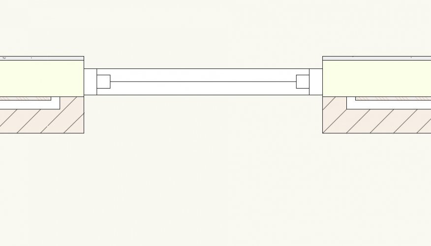
Splay command is in the settings dialog for the windows. Materials is something new to VW2021
-
I just now tried playing around with the new materials in VW 2021 plus the splay command for the windows to achieve basically the same thing that Christiaan is suggesting.

-
I use the curtain walls all the time to create our storefront windows. I typically create a window (or door opening) into the wall the size of my storefront. Then once I create my curtain wall door/window assembly I group it and place it into the opening.
-
I created two design layers, Layer 1 I drew some objects then made a Design Layer Viewport of the objects on Layer 2. On layer 2 I mirrored the viewport. So now whatever I draw on layer 1 is mirrored on Layer 2. Is this what you are looking for. Example file attached. Note you made need to activate layer 2 to get the view to update. Mirror.vwx
-
domer1322 - I hear you. Technology keeps improving and there is always this constant leap frog software and hardware. So sure eventually old software becomes unusable. But with a current VW license you could probably go 4-5 years. With Revit your license is dead the minute you stop paying the annual fee.
-
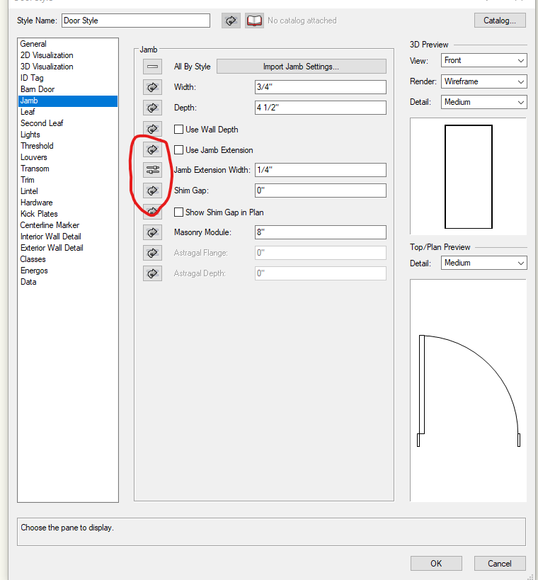
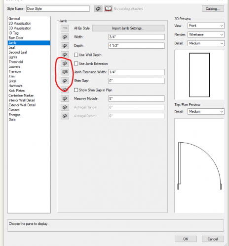
alfresco - not sure if this is the problem you are having. There are styled and unstyled door and window objects. If you are using unstyled doors you should be able change everything from the worksheet. If you are using styled doors every parameter of the door object can be set to "by style" or "by instance". Parameters that are set to by instance can be changed in the worksheet. Parameters that are set to by style can only be changed by editing the Plug in Object.
-
How to make multiple stories visible at the same time?
TomKen replied to Marshallae's topic in General Discussion
Make sure your layers are set to show snap others or show snap modify others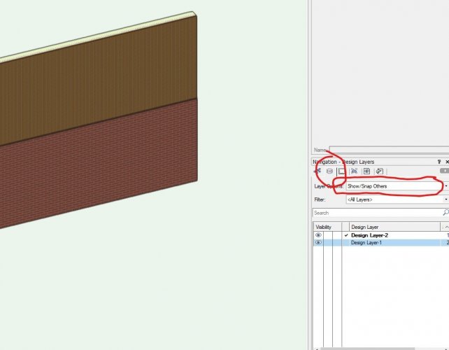
-
I've used a number of different CAD softwares over the years, started in AutoCAD (when it was DOS), used Architectural Desktop, Inventor, Rhino, Chief Architect, Vectorworks and tried a number of other programs like ArchiCAD. All the programs have things that they do really well and they all have their weaknesses and they all have things they do the same it is just a matter of where you find the tool and what buttons you have to push. I started in AutoCAD and even taught it for a while but I left it behind years in ago in favour of BIM programs. I wish you could take the best of each program and mash it into a single super program. What I've found in my experience is that it is not which of the major BIM programs you use but the willingness of users to learn how to drive the program to it's full potential. Our office uses Revit and Vectorworks, although I use mostly VW. I have co-workers who have used VW since the 90's and still draw section marker manually, use none of the plug-in tools for windows doors and stairs etc, yet they update to the latest release every year. Fortunately there are a few younger and more open minded people in the office and I've been teaching them how to use VW as more of a BIM tool. We have an open office it's fun to listen to some of the senior people standing over the shoulders of juniors now as they spin the model around and cut live sections for them to look at and they go WOW! I didn't know you could even do that. Also helpful when the construction management company calls you says they are not clear what is happening in part of the building and you just use the clip cube and send them a 3d screenshot. So back to the original question Vectorworks Vs Revit, they are both competent programs. I like Vectorworks more as it is much more affordable, and the fact that your license never expires. You can chose to be a subscription member or not. For a single user office (like I used to be) this is a big deal. If I was still working solo I probably wouldn't be able to generate enough revenue to justify the current cost of Revit (also being close to retirement I don't want to have a CAD program that I need to keep paying for simply because I want to do a little CAD work). My two cents.
-
2021 - Teaser Tuesday: Automate Your Workflow with BIM Improvements
TomKen replied to JuanP's topic in News You Need
3d improved Grid Tool, hope there are more tools like that. I always work from a 3d BIM model. But in the end I need to produce construction documents. I've wasted hours of time putting Grid lines on Section and Elevation Viewports so this will be a big time saver for me. Hope it will work for Section markers as well. -
Garage slabs below Main floor and Garage doors for 3d models
TomKen replied to Patrick Davis's topic in Architecture
Wes, I used to use the reshape tool for door pockets in the foundation but I found wall recess simpler. For example if you move the door you can move the wall recess fairly easily. That being said I use the reshape tool for things like stepped footings as you've shown in your example. -
Garage slabs below Main floor and Garage doors for 3d models
TomKen replied to Patrick Davis's topic in Architecture
When I do Garage doors I usually also need to create a door pocket in the Stemwall. I do this by creating an extrusion and turning it into a wall recess (found in the AEC menu.)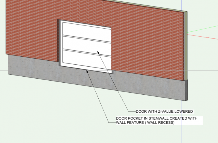
-
Select the elevation marker and then in the attributes pallete set the line weight to none -----. This only affects the line and not the marker.
-
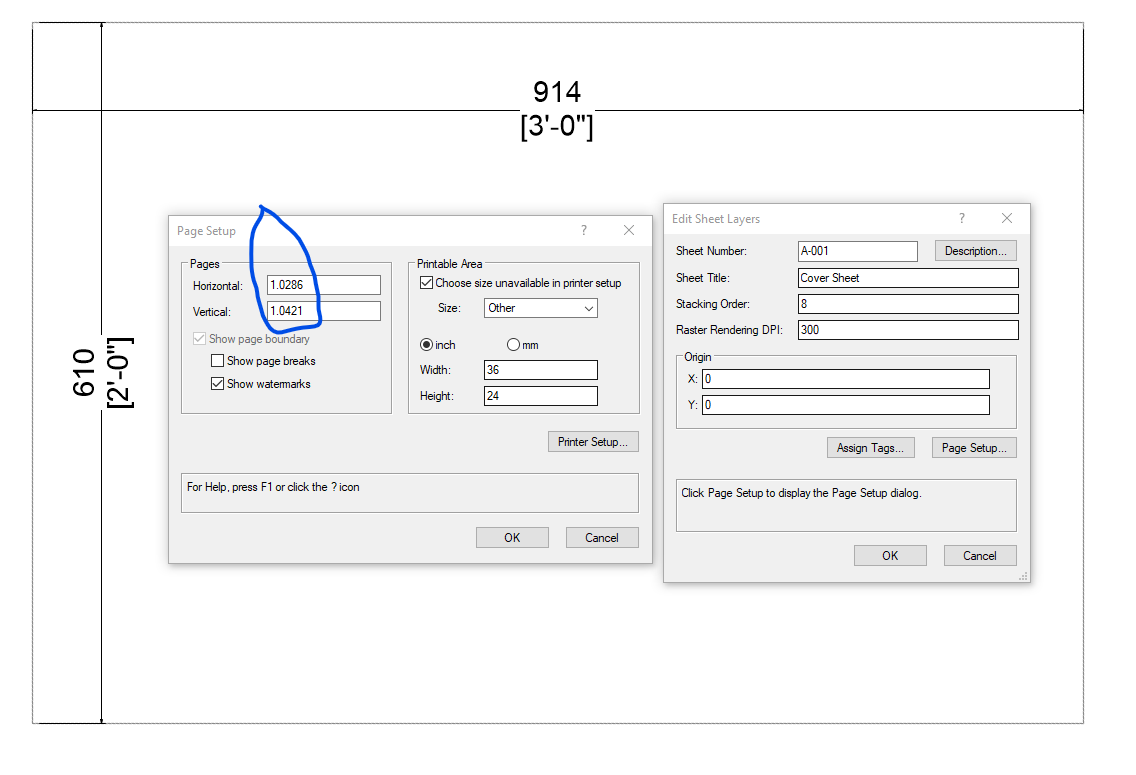
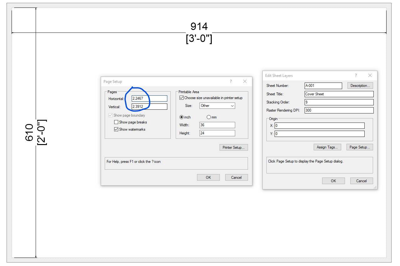
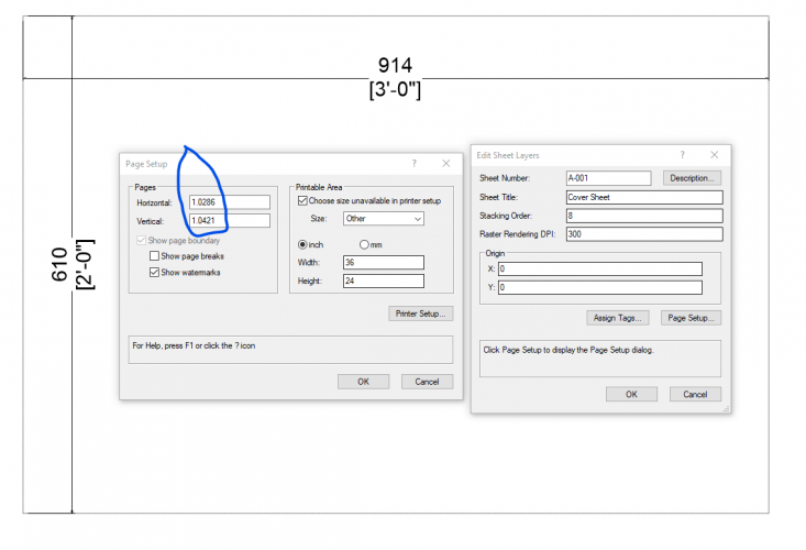
O.K. I think I have it figured out. Both files are now open on my home office computer, File one was originally set up on my work office computer, File 2 was set up on a consultants computer. All with different printer configurations. But as you can see in the attached images both sheets had the same page set up. The only difference I could see between the two sheet setups was the number of pages it makes to up a D-Size sheet. I think it was remembering this information from the computer it was first set up on. If I go to printer setup on my computer and pick the same size paper for both then the boundary matches. Ultimately it doesn't matter in the end, it is just sometimes I have sheets without titleblocks and I like to see the thick boundary outline.

-
Pat, There is are no titleblocks on these blank sheet layers from two different files. In one file the boundary is nice and thick, in the other it is simply a line. This is what I'm trying to find a setting for. It has nothing to do with the titleblock. Cheers


-
Nikolay, Boh, Thanks for your response but this is not what I'm looking for. I'm specifically talking about Sheet Layer Page Boundary not Design Layer Page Boundary. I'm also not referring to the size of the sheet in page setup, I'm talking about the thickness of the line that defines Sheet Layer Page Boundary, In the first image the boundary line is 13mm thick, in the second it is only a line. My question is how do you control the attributes of the Sheet Layer Page Boundary (which also has nothing to do with the titleblock setup as far as I can tell). In the Vectorworks preferences dialog under interactive settings you can change some of the attributes of the design layer page boundary and you can change the background color of the sheet layers but I don't see anything for the boundary of the sheet layer. Hoping someone can answer this question. Thanks
-
So for my drawings on sheet layers I always have a grey page boundary that surrounds my titleblock. I like this. I have a drawing from someone else in the office and there is no thick grey boundary around the titleblock (same company titleblock) . I can't for the life of me find a setting anywhere that allows me to control the appearance of the sheet layer boundary. Does anybody know how to do this? Working from home and I see I don't have my signature set up. Ryzen computer running VW2020.


-
Publish command is printing sheets in reverse order
TomKen replied to TomKen's topic in General Discussion
What? No record? That is not true Nina in this thread said it is a known issue and they are working on it. -
I haven't figured it out yet. Pretty sure it is a bug in VW2020
-
Nice model of your balcony sliding doors.
-
The office I work in the past always used VW as a 2D drafting program, since I started here I've done all my projects as BIM models and taught others in the office to do the same. My biggest pain, trying to issue a set of 100 drawing sheets with viewports that need to be updated on about 50 of the sheets. We use Vectorworks because a lot of our clients are also using the same software. We also use Revit in our office and I've done lots of projects large projects with that software as well. No waiting for Viewports to update in that program. There are lots of things I like about VW but updating viewports isn't one of them.
- 1 reply
-
- 3
-

-
Dual Units for Dimensions
TomKen replied to Bruce Kieffer's question in Wishlist - Feature and Content Requests
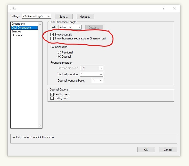
Bruce, Just checked and yes it can. Go to File/Document Settings/Units. and check show Unit Mark.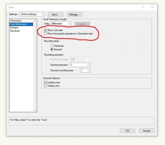
-
Dual Units for Dimensions
TomKen replied to Bruce Kieffer's question in Wishlist - Feature and Content Requests
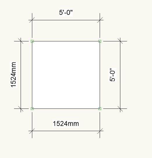
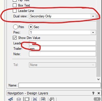
If you are using imperial units, create a regular dimstyle. For the mm dims create a dual side by side dimstyle and turn the Primary dimension display off in the OIP and add a mm trailer. If you are using metric units do the opposite. I would put one of each dimension type in the drawing area somewhere and use the create similar command to quickly switch between them.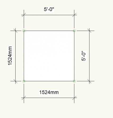
-
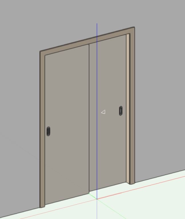
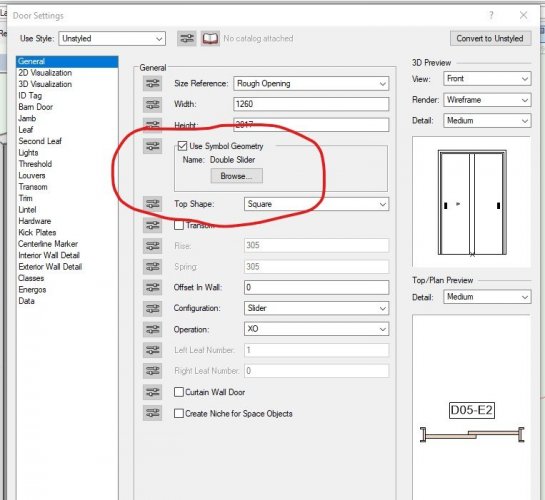
I made a copy of the door, turned it into a group, edited it then made a symbol. In the door PIO I checked use symbol geometry. You could also create a custom door leaf.
-
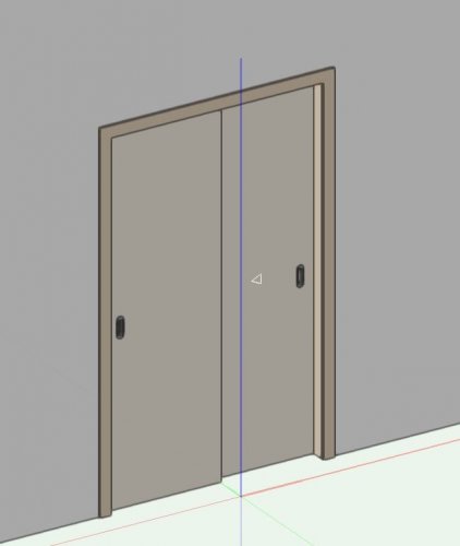
Challenge accepted. sliding-door-challenge-complete.vwx
-
Create an extra design layer with an flat extrusion object above the wall you want to removed the peaks from, at an elevation you would like the walls. Select the walls you want to change the peaks on then run the AEC fit walls to objects command and choose fit to objects on the layer you created. This will remove the peaks from your walls.