
JustinVH
-
Posts
600 -
Joined
-
Last visited
Content Type
Profiles
Forums
Events
Articles
Marionette
Store
Everything posted by JustinVH
-

Circle Trusses and their weights - Vectorworks 2020/2021
JustinVH replied to martin.vacek's topic in Braceworks
You can adjust the weight of the piece of truss yourself in the Truss Properties dialog to match what is given from the manufacturer. We are currently working with Eurotruss to do a complete review of all of the Vectorworks symbols and correct any issues with weights and other items. There is no timeframe for completion but luckily those are user editable values.- 1 reply
-
- 1
-

-
Prolyte H40V box corner - struggling to configure correctly
JustinVH replied to Mike Wright's topic in Entertainment
Thanks for pointing this out. That is an issue that I will be fixed. All truss should have a cross section assigned so that Braceworks will function properly. If the data is not available then it should be set to Rigid. Regardless, all truss should have values in length and width. -
Prolyte H40V box corner - struggling to configure correctly
JustinVH replied to Mike Wright's topic in Entertainment
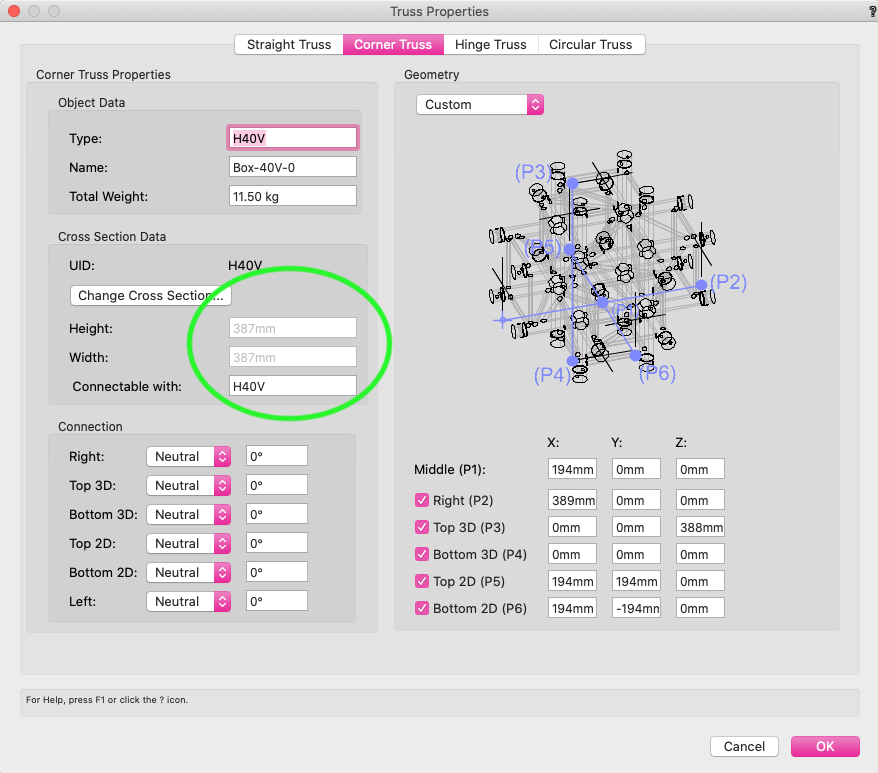
I took a look at the file and the issue is that the cross section values are showing the truss length and width dimensions of 0mm (screenshot with blue oval). If the dimensions have no values the auto connect will fail and that is why things were not connecting to the left. I was able to fix this by going into the Truss Properties and reassigning the H40V cross section to the piece of truss and clicking 'ok' in the dialog. The trick is to make sure that the length and width are 387mm (screenshot with green oval). By reassigning the cross section the length and with will auto populate because the dimensions are defined by the cross section. Once I corrected the missing dimensions the truss corner behaved like expected.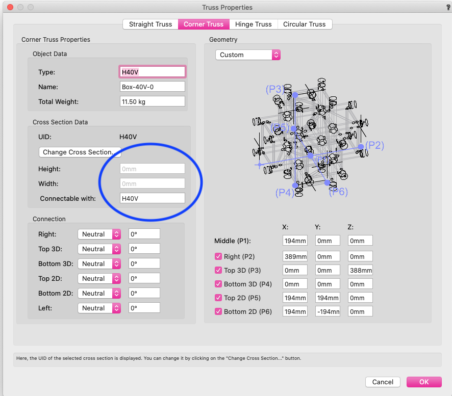
-
Prolyte H40V box corner - struggling to configure correctly
JustinVH replied to Mike Wright's topic in Entertainment
@Mike WrightAre you able to share the file so I can have a look? You can message it to me is needed. -
@FlavieI would agree with Mark's comment about the 10% rule. The way I always remembered it was that the Field angle was the full outline of the beam so I always related the first letter of field and full to align with each other. For the Beam angle 1 vs. 2 and Field angle 1 vs. 2 the Field angle and Beam angle are the vertical spread of the light when it is facing upstage so the spread along the Y axis. The Field and Beam angle 2 are the horizontal spread or the width so this is the direction along the X axis in the same position. For a PAR that has a 30° vertical beam and a 50° horizontal beam Field angle would be 30° and Field angle 2 would be 50° to produce an oval beam. Hope that helps.
-
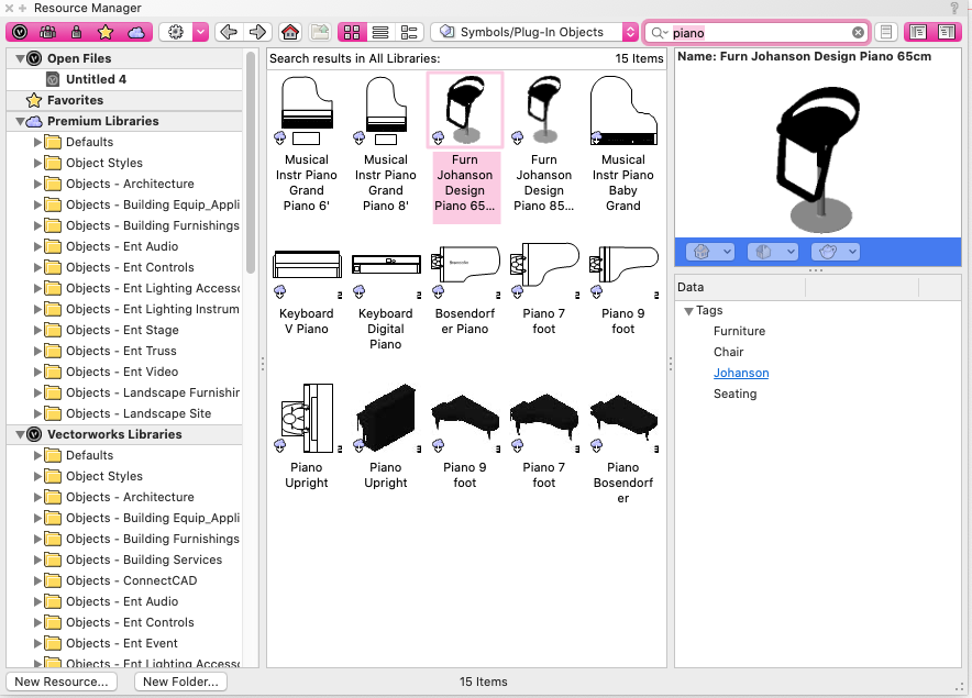
@matt stevensI searched the RM in VW 2021 using the word piano and found several symbols and there is a baby grand piano in there.
-
Also, make sure that you are in a Spotlight or Designer workspace and inserting the truss using the Truss tool. The symbol may be inserting as a 2D/3D symbol and not as a truss object.
-
@C. Strong TouringI just sent you a direct message with the recording.
-
I have attached a movie of my workflow. I am having no issues using GT Truss from the RM in 2021. Screen Recording 2021-08-25 at 10.35.57 AM.mov
-
@C. Strong TouringYes, you can manipulate truss in 3D using the Roll, Hanging Angle, and rotation fields in the OIP. Keep in mind though that this will strip the 2D portion of the symbol to reveal only a 3D symbol.
-
In a 5 way corner the open end of the corner is considered the top so this particular symbol is upside down so that will be corrected for the next version. It is an older symbol and was missed when the standards were changed a couple of versions ago. When I build truss structures that beed to be built vertically I always do so from an isometric view so that I can pick whether I want to build up or down as the default direction is down when building in Top/Plan view. In order to have a 5 way corner with the open to the side you have to manually rotate the corner once placed or make a duplicate symbol and adjust the 3D geometry so that the open end is on the side that is preferred. I was able to manually rotate the corner using the rotate tool to get the open portion to different directions. It appears that when the hanging angle of 90° is used to insert a vertical truss the corner connections get rotated oddly. This is what was causing the open end to be in an odd location. I found that if I insert the first vertical leg on the ground from a Top view and connect the corner I can then switch to a front view and use the rotate tool to rotate the whole structure vertical. From there I can connect the remainder of the truss to complete the rig. I have also attached two corners for you, one with the opening at the top which is correct and the other with the opening to the right. When you place the corner with the right opening onto a piece of truss on the ground and rotate to vertical the opening will be at the top. 5 Way Corner Extras.vwx
-
It looks like the issue is not with the truss corner as the corner is setup properly. That particular corner has no Bottom 3D connection as it is a 5-way corner and the geometry reflects that as there are no gussets on the bottom. This may be a bug in the truss code and not the content.
-
It looks like the setup of the corner connections is incorrect in the Truss Properties window. I am going to DM you a document that shows how to set up all the different pieces of truss.
-
You can convert to truss at any point. If you go into the 'Edit 3D Component' of the truss that is having issues you can adjust the geometry there. When I make the truss for the default content I always place the geometry properly before making the symbol out of habit but it is not necessary. The "Edit 3D Component' mentioned above willed you fix any issues.
-
Currently, where is the insertion point of the truss? All trusses must have their insertion point be on the left edge and centered between the chords and the bottom of the geometry should be at Z=0.
-
I am going to also tag @jcogdell as well as he may be able to confirm better but if you are using an existing cross section like the H30V and save the symbols to your user folder you should be able to keep the symbols with that cross section for future drawings. Every time we at Vectorworks release new content all content gets overwritten with the new code so you need to save it so that you can access so changes don't mess up your custom setup. As mentioned, @jcogdell may know the best workflow so that is why I am mentioning him.
-
The way to access the "Customize Truss Symbol Data" button is to insert a piece of truss and then right click on the inserted symbol on the design layer. This will bring up the menu where you can select the customize button.
-
Currently truss corners can only rotate if there is a cross section on the truss. ASD has not provided us with cross section data therefore all of their truss is set to rigid. Truss that is set to rigid will only allow corners to connect in two directions. This is the reason that Eurotruss and Prolyte function properly, they have a cross section with structural data applied to them.
-
3D geometry invisible in Ampeg Vectorworks Library File
JustinVH replied to ajpen's topic in General Discussion
@ajpen The best contact is tech@vectorworks.net. Someone there will be able to assist you and file the bug if needed. -
3D geometry invisible in Ampeg Vectorworks Library File
JustinVH replied to ajpen's topic in General Discussion
Have you reached out to tech support with this issue? If they are not able to come up with a solution they will file a bug so that the engineers can investigate. -
This is a bug that is currently being investigated by the engineers. At this point in time there is no timeframe for a known fix.
-
I have reached out to my contact with Area 4 to see if I can get the necessary files. I can't give a timeline for inclusion in the software but if I get the files I will post them in this thread.
-
In order to change the record you need to go into either the 2D or 3D component of the symbol. From there in the OIP you will have access to the Truss Record and should be able to change the color of the truss record. This will not change the color of the truss, just the record for that symbol.
-
@Endre Torkildsen I am going to send you a DM to discuss the parts you have created.
-
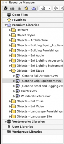
There is now a library in the Premium VSS Content containing various kinds of grip equipment, C-stands, Rocky Mountain C-stands, and clamps located in the Objects>Ent Stage folder. This content is exclusive to subscribers of VSS and is included in both 2020 and 2021 versions. All of the components of the adjustable hangers and stands are setup as groups within the 3D component of the symbol so that the sections can adjusted for height within the symbol or the symbol can be converted into a group after insertion and adjusted. There are also 3D loci serving as snap points to help connect different elements together easier.