


JustinVH
-
Posts
597 -
Joined
-
Last visited
Content Type
Profiles
Forums
Events
Articles
Marionette
Store
Everything posted by JustinVH
-
@livespace josha Are you able to send me this file by DM so that I can take a look? I setup the auto connect settings for all of the truss that is shipped in the Resource Manager and I have not experienced this type of behavior that you are showing. Are those Christie Lites Type A symbols or some other manufacturer? If they are Christie Lites Type A part of the issue you are having has to do with the corner and the gusset plates. The gusset plates actually lie outside the "box" of the straight truss and because of how the 3D symbol for the corner is laid out the corner shifts by 3/8" when snapping using auto connect. In plan view the corner block and upright are not perfectly aligned like the real world and the auto connect is having trouble finding the side snap points. If you are able to send the file I would love to take a look and see what else could be causing the issue and see if I can fix it in your file and send it back to you or find the cause and file a bug. I made a quick video using Christie Lites Type A 6 way corner block and a 8' straight piece of truss to assemble a goal post and the auto connect worked as I would expect but I had to use right or left isometric views as I find they help when assembling truss vertically. When I tried to connect from a top view I did also have the struggles that are present in your video. Truss Corners.mov
-
@Wade You should make sure that you save a copy of your modified .txt files somewhere on your desktop as well. When Vectorworks gets updated through service packs or new releases the .txt files that are in the installer may override your custom changes and you will have to do the work again to modify your signals and connectors. I am not saying this will happen but just wanted to give you a heads up so you don't risk losing your work and can just replace the .txt file quickly.
-
@a guy Is there any way that you can DM me the engineering data for the truss and I can take a look. I just create the geometry and setup the auto connect information. The Braceworks information is setup by our structural engineer and then coded into the software. I may be able to decipher though if you send it to me, no promises though.
-
@Peter Neufeld You are correct. The only way to change the cross section is throughTruss Properties page by right clicking on a truss symbol.
-

Rotation of symbols in resource browser...
JustinVH replied to anthall5's topic in General Discussion
@anthall5 Not a problem to help you. Litec was released in the September and November 2019 updates to the Service Select libraries. Most of their products are in the software now but still need the Braceworks data for calculations. They can be found in the Service Select Libraries>Objects-Ent Truss>Litec folder and you can use those as a guide for setting your symbols up or modify them to your style. The DADO connectors are in there as well to use as a guide. They are setup just like corners but you have to make them X-Corners and so some crazy math. You can DM me if after looking at the existing libraries you still need some help. I have attached a screenshot of the Litec libraries in the RM for you.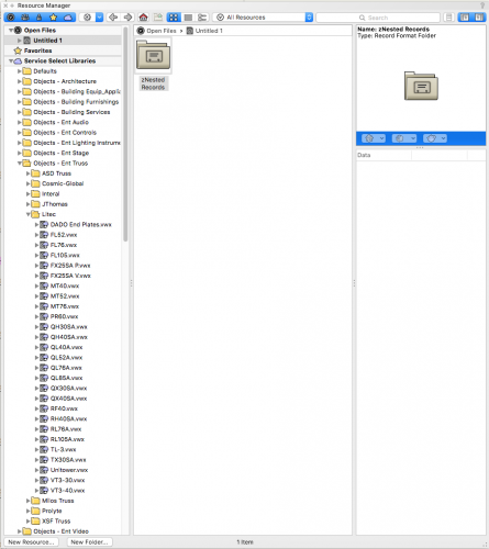
-
Rotation of symbols in resource browser...
JustinVH replied to anthall5's topic in General Discussion
@anthall5 If you need any assistance making those symbols into fully functional truss symbols with auto connect please let me know. I build and setup most of the truss that ships in the default content so I would be glad to answer any questions you have. Those look like Litec truss which is also not included in the Vectorworks Service Select libraries if you are a member of this program. I know that Litec is working on getting us the Braceworks data as well so at some point in the future you may be able to connect your custom symbols to a Braceworks cross section and have full functionality. -
@stayathomedad Are you talking about the auto connect cross that is in the end and in the middle of each truss symbol or are you talking about the Insert Points loci?
-
@Zach Are you using VW2019 or VW2020? Those items should have been fixed for 2020?
-
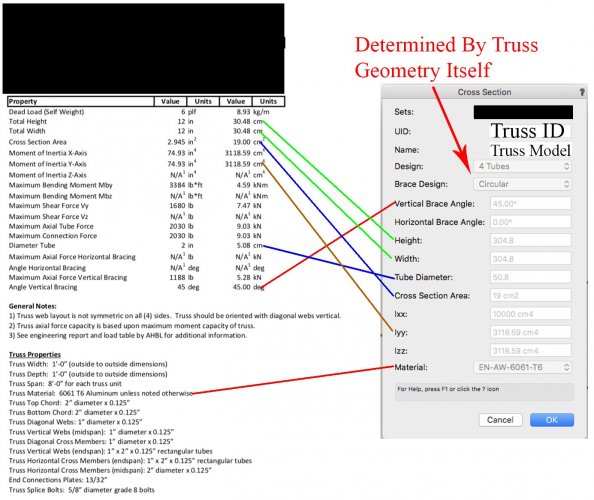
@BMYDesign At this point in time there really is no HOW TO or documentation for adding your own engineering information. This is all done through code and XML files for all shipped content. I am currently working on creating a document in between working on manufacturer libraries to explain all of the steps from creating the truss geometry to making it Braceworks compatible but there is no timeframe for completion. I have attached an image for you that shows what elements of the engineering data are needed and where they are placed in the Cross Section data in the Truss Properties window. To access this page simply open the Truss Properties window and choose "Change Cross Section". A window will open where you can enter all of your engineering data and choose the appropriate shapes from dropdown menus. Keep in mind though that custom truss cross sections DO NOT transfer from document to document. If you try to import the custom symbols into another document the cross section will be removed and the truss will return to a Rigid cross section. Please let me know if you have any questions.
-
@rseybert Sorry to hear your frustrations. At this point in time with the current coding that particular hinge does not function with Braceworks or Auto Connect and that is why the Truss Record has been removed and it is just a 2D/3D symbol. Currently, book hinges can only function if the hinge pivot is at the bottom of the symbol in Top/Plan view and center hinges can only function if the hinge pivot is through the Y-axis of the symbol in Top/Plan view; this results in the pivot actually being in the center of the hinge when viewed from a front view in 3D. Any hinge that has the Truss Hinge Record attached is a non functioning hinge and will not work with Auto Connect or the hinge code. The record is there so show the weight and model number so if there was a need to use it a point load could be added if desired. The reason the hinges that don't support the functionality were left in the software was so that users could still use them as manual symbols as some rental houses keep them in inventory. There is a workaround though. You should be able to use the TC1212 AVB symbol from the same Tomcat library and after inserting into your drawing, rotate the hinge from a side view by 90°. This will remove the 2D geometry and place the rotation point through the Z-axis as you desire from the TC1212 AHB model. From this point the hinge degrees will work and you will be able to choose an angle. The only thing visually you will notice is that the bolt plates will be 90° different between the hinge and truss. If you have any more questions feel free to DM me and I will assist if I can. Justin
-
@Rob Lloyd At this time there is no on demand service for truss like there is for lighting fixtures. Any truss requests that we see on the Wishlist-Feature and Content Requests page of the forum are placed into the queue of truss to be made. That order of the work in the queue changes based on my workload and whether or not the manufacturer has/is willing to sign an agreement to be in the software and provide all of the data. If a major truss supplier approaches us and signs on to be in the software and provides all of the data quickly the order in the queue gets shifted. I generally try to create a mix of US and EU/world manufacturers for each VSS release based on the list.
-
They are located here: Vectorworks Libraries>Objects-Ent Lighting Instruments>Lighting Stands I also had success searching Manfrotto in the RM search function.
-
This should work for you. To connect the lower T you will have to hover pretty high on the symbol as the rest of the T is missing because it is made of the other straight pieces of truss. Let me know if you have issues, I tested it and it worked for me. JThomas B1304 T.vwx
-
Please post your file if you are able/allowed and I will take a look and make it work if I can. I will probably have to make a duplicate symbol as I only set up the gates to function as traditional corners and not T-Corners. If you can't post your file please let me know what gates you are using and I will send you a replacement symbol.
-
@mlance What version of Vectorworks are you using? In VW2020 the gates were setup to properly work with the auto connect feature.
-
@grant_PD Are you able to post your files with the Tomcat truss?
-
Here you go, I made you a 2019 T-Link file. Let me know how they work for you. Christie T-Bars v2019.vwx
-
@acdeslx What version of Vectorworks are you using? There were some improvements done to the files in VW2020 and the T-Link bars work and make the angle.
-
There is also a generic library of cheeseboroughs in the Objects-Ent-Event folder in the Resource Manager. Although not adjustable there are 3d symbols in 15 degree increments as well as rigid versions that can be used for populating worksheets and reports.
-
Inserting Global Truss T-part with insert truss tool
JustinVH replied to Anttti's topic in Braceworks
@Anttti I have taken a look at this truss and this is indeed a bug in the way the corner piece is drawn. I am going to file a bug and correct the issue and in the meantime I will fix the symbol and send you a file with the corrected symbol so that you may use the truss as intended. The corrected symbol is attached. Justin Cosmic F34T35.vwx -
Hello again, Those truss bases were in an old library and were not setup for the auto connect and that is why you were having the issues. I have attached a file for you with the base setup using auto connect so that you may properly connect vertical truss like you wish, simply import the symbol into your drawing and use as you wish. In VW2020 the truss libraries have been updated and some new truss bases as well as Prolyte spacers were added so that if you choose to upgrade in the future there is a lot more that can be done with the Prolyte libraries as well as how vertical trusses are created. Prolyte H30D Base.vwx
-
What version of Vectorworks are you using? It does not look like 2020 as I still see vertical truss symbols. If possible, are you able to attach the file so that I may take a look. Triangle truss are the most difficult to get to setup and I would like to have a look so see if the symbol is setup correctly.
-
If desired the red box can be turned off by turning off the Lighting>Input>2D or 3D class respectively.
-
New hinge corners do not work as advertised... 2020
JustinVH replied to Ryan Seybert's topic in Entertainment
@LMorga I tried the truss straight out of the resource manager and I had no issues with the TC1212-AVB and TC1212-VHB as you also report. However, at this time the TC1212-AHB and TC1212-VVB are not supported. It was decided to leave the hinges that are not supported at this time in the program but change them to regular 2D/3D symbols in case there was a user that needed them. The only way to make them hinge is to manually adjust the 3D geometry in the Edit 3D Components window of the symbol. They will not support auto connect or calculations but at least they can be used. The other workaround is to take the TC1212-AVB and TC1212-VHB and click the 3D only radio button in the OIP. This will allow the hinge to be rotated in 3D views but it will still function as a hinge. If you have any further questions please DM me and I will see if I am able to assist. -
@SuniAre you using version 2020 or are still using version 2019 like your signature? I just want to make sure that I use the correct version when I list your workflow.


