


Marissa Farrell
-
Posts
1,474 -
Joined
-
Last visited
Content Type
Profiles
Forums
Events
Articles
Marionette
Store
Everything posted by Marissa Farrell
-
Personally, I use Craftware as my slicer. I'm able to scale to .5%, I'm not sure how drastic the rounding errors are.
-

Trouble with the resulting size of a solid subtraction.
Marissa Farrell replied to Bruce Kieffer's question in Troubleshooting
Hi Bruce, This will end up being a very controversial conversation, however I want to point out that this likely isn't Vectorworks' fault. Computers, when doing math, have rounding errors that aren't always handled the way that the user would expect. Hopefully this article can help clear it up, at least a little. https://blog.codinghorror.com/why-do-computers-suck-at-math/ -
Before you use the loft tool, select your NURBS curves and check 'show direction' in the OIP, then when you use the loft tool and cycle through your curves, the direction will display.
-
Currently the worksheet nodes don't ship with the software, the only ones are the ones available on the forum. I'm traveling now, but hopefully @JimWcan link you to the appropriate resource.
-
How to move visible objects (not on the active layer)
Marissa Farrell replied to Taproot's topic in Vectorscript
Glad to help! -
How to move visible objects (not on the active layer)
Marissa Farrell replied to Taproot's topic in Vectorscript
I think if you change the "ForEachObjectInLayer" line to ForEachObjectInLayer(Fnm,2,0,1); then it should do the trick? I'm only assuming based on the devwiki's description. http://developer.vectorworks.net/index.php/VS:ForEachObjectInLayer EDIT: I just tested, and it appears to work. -
Multiple records in 1 marionette script
Marissa Farrell replied to Nico Vindevogel's topic in Marionette
Hi Nico! I'm going to do my best to explain this to you. I've attached a file with a modified version of your original Marionette object. What I did: Instead of using the Parent PIO node, I used the resulting object from your Linear Extrude nodes as the 'obj' input to all of the record nodes. This will allow the record to attach only to the extruded rectangles rather than the entire Marionette object. In order to create a report that shows these records, it's very important that in the "Create Report" dialog box that you select "Options..." and check "Search in plug-in objects." The report will not see those objects otherwise. I increased the lineweight on the nodes that I changed connections on. I hope this helps! Please let me know if I need to clarify anything further. RecordsAndMarionette_MFarrell.vwx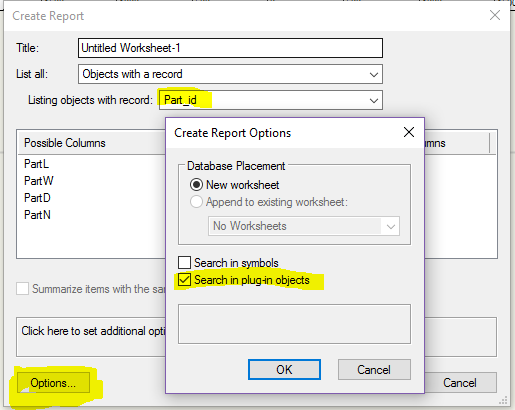
- 10 replies
-
- 1
-

-
- marrionette
- record
- (and 1 more)
-
Multiple records in 1 marionette script
Marissa Farrell replied to Nico Vindevogel's topic in Marionette
Hi Nico! Can you clarify for me, are you hoping to have each of the extruded rectangles have different record data, or are you trying to attach the record data to the entirety of the Marionette object? Both are possible, I just want to make sure we're on the same page before I take things in an entirely different direction than you're looking for. Also, if Alan's example helped at all, then that's great as well Marissa (aka MFarrell I wrote those nodes.) -
Version 1.0.0
69 downloads
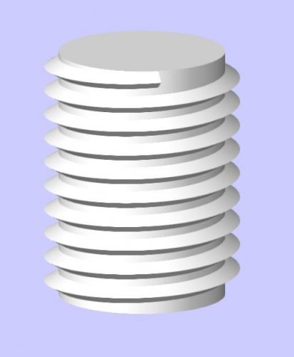
Attached is a Marionette Object of a threaded bolt, still in progress. Current "NumThreads" must be >0 and <=10, or you will get a failure. This will be fixed (and later removed and replaced with overall length). Fractional values should work. There is much more ahead on this, but I figured sharing now and allowing the community to play with it/improve on it could be beneficial. I will update the variables as I go to follow standard dimensioning of threaded objects, I just haven't gotten around to the math in some areas (such as major diameter, etc.) It will also later include a head, since that's obviously not there -
Version 1.0.0
45 downloads
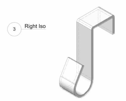
I've recently purchased a 3D printer (I'll share more details with anyone who asks ) and decided that it would be fun and gratifying to begin modeling objects using Marionette with the intention of printing them. My first share is this parametric door hook. Although simple, it was a great drawing project (I actually took much longer on this than I thought I originally would...). Once I get around to printing one (or four) out, I'll happily share the results! If there are any questions on the best practices for using Marionette to model for 3D printing, I would love to be a resource for you. I'd also love suggestions as to what other objects might be fun to model for print! -
Version 1.0.0
43 downloads
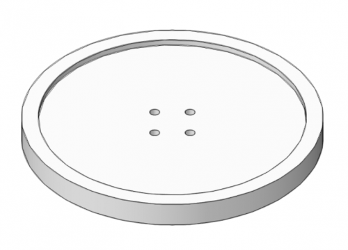
A parametric button - again, simple. Please let me know if you run into any issues while changing parameters in 3D - there's an inconsistency I'm trying to track down. Not shown in image - you can choose the number of holes to thread through. -
Okay here's an updated version with OIP controls that allow the changing of both circle radius and font size. CenterTextOnObject_MFarrell_v2017_v02.vwx
-
Hi Scott - Here's a post that has an example similar to what you're looking for. Take a look at this and see if it helps you, if you need a little more guidance, let me know and I'll do my best to quickly help you!
-
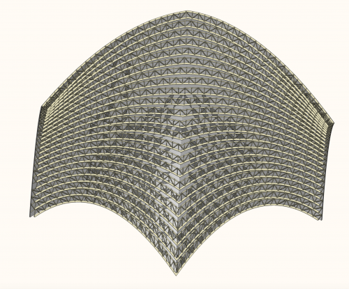
Version 1.0.0
845 downloads
The 3 attached files demonstrate using Marionette to generate a roof truss from a guide curve. - Truss Network.vwx : This file contains a network that uses a named curve and some dimensional input parameters to produce truss geometry as extrudes on the layer plane. - Truss Node.vwx : This file wraps the truss network from the first file and uses it within another network. This network takes a freeform NURBS surface, slices it into a series of curves using the contour node, and generates a truss from each curve. - Truss Object.vwx : This file demonstrates the truss network wrapped and converted to an object. You can change the parameters in the OIP or reshape using the reshape tool. -
IF Node performing a Mix2 at the same time?
Marissa Farrell replied to Stephan Moenninghoff's topic in Marionette
Most nodes will repeat the last item of the shortest list when they are run, which is what you are seeing here. Deleting duplicates would be a good way to fix those errors, as long as there aren't any others that would have the same value that you would need. Another way to handle this would be to return the first x number of items in the list, with x respective to the length of the shortest list. You could probably use the 'Split List' node to do that. -
I updated that post to use the correct links! Hope this helps!
-
@Alan Woodwell and @DSA, are you referring to the file attached at the very beginning of this thread, or somewhere else? Because I am having no issue running the infographics file from the earlier post. I'm attaching the 2017 version here, in case this can help remedy your problems... Infographics_v2017.vwx
-
It appears that the same issue is happening to both of your files when updating to 2017. @Alan Woodwell- in your 2017 file, for some reason the output from your 'add' node is also being wired to your x port on your lower 'Point 2D' If you remove that wire, your network works fine. @willofmaineAlthough you only attached your 2017 file, it appears that you may also have an extra wire. If you go into your network, I'm assuming the '2Run' node should not also be wired to that top 'Point2D' I don't know why this is happening, but I will file a report on them and see if someone with more knowledge of the backend can figure things out.
-
Slider Control With Input Ports?
Marissa Farrell replied to Stephan Moenninghoff's topic in Marionette
I will follow up with this idea though - you could use the slider node to define a percentage of a range of values, or even a factor, it just would not directly reflect in the OIP. -
Slider Control With Input Ports?
Marissa Farrell replied to Stephan Moenninghoff's topic in Marionette
Unfortunately at this time, this isn't possible. There's no way to define an OIP control dynamically. It's definitely on our list of things to try to improve, but we so far haven't made any headway. OIP controls must be statically defined. -
Okay, I modified the node I created last year... This appears to solve the issue, at least on my end. It does still have some limitations that will require some more handling, but I think it should work for what you're trying to do right now. Let me know if you run into any issues. SplitList_NEW_MFarrell.vwx
-
This doesn't look right to me. I'll try to take some time today to see what's going on.
-
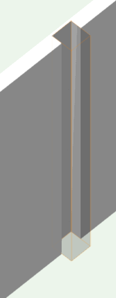
Pat beat me to it - here was my example. This is using a 3D Wall Hole Component that matched the extrude exactly. EDIT: with a proper Hybrid object, Top/Plan could look like this:
-
Without actually testing this - I think there is a way to query if the object is inserted in a wall, which would allow us to get the parameters (i.e. thickness) of the wall and take it into consideration when building in that missing piece. Food for thought. I will look into it as soon as I have more free time. EDIT: I'm actually 90 percent sure that we can just define how far into the wall the object will cut. Will update when I verify this.
-
I updated the first post in that thread with Robert's original files. Let me know if there are any others you need.