


zoomer
-
Posts
8,898 -
Joined
-
Last visited
Content Type
Profiles
Forums
Events
Articles
Marionette
Store
Everything posted by zoomer
-
3DConnexion SpaceNavigator Configuration
zoomer replied to PVA - Admin's question in Troubleshooting
MMB Drag seems to work without lag. And I notice that Apples Magic Mouse scrolling doesn't work nearly at all and finally lags the whole GUI including click to open Menus. I even removed all 3DCon Devices and did a reboot. Magic Mouse doesn't work. works even worse when hovering over geometry -
3DConnexion SpaceNavigator Configuration
zoomer replied to PVA - Admin's question in Troubleshooting
Yes it does too. And that is nice as it seems you can access center settings options while spacemousing and that way that setting is kept for the 3D device. That lag appears even more often with normal mouse usage than effecting Enterprise. Mainly Zoom by Scroll Wheel. And it may be worse when hovering over complex geometry opposed to just a single solid. here are my highlight settings :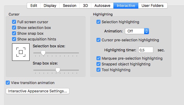
-
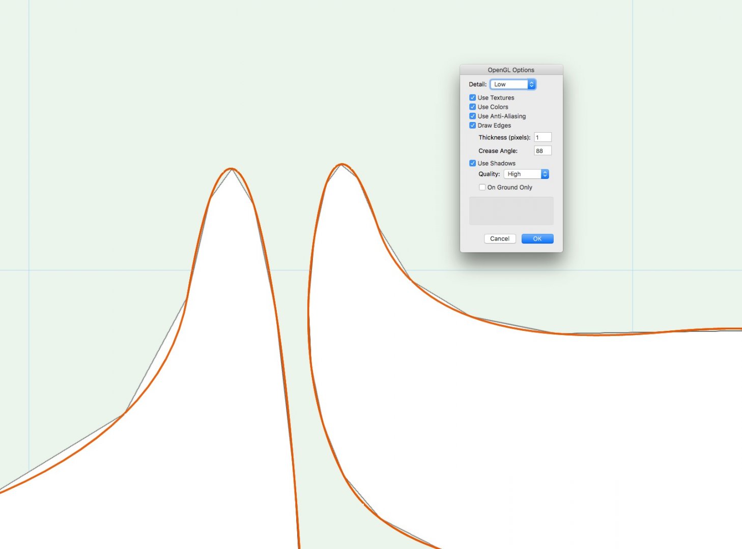
Nice Booth Maybe my assumption was not 100% correct anyway. At least not so noticeable in my screen shot. Right Object is about 10 times smaller. Deviation looks max 2 times coarser for the bigger one, if not just because of geometry differences only.
-
I made a bubbelish Polyline and extruded it. It worked fine according to OpenGL roundness quality settings. But I looked closer to a part of that quite large Polyline Extrude. When at a part with a much smaller radius vertex, it looked too coarse. So I drew a much smaller, similar bubbelish thing beside that problematic area, and the rounding was much finer although the radius even smaller. That is why I think the deviation value depends on the size of the object.
-
3DConnexion SpaceNavigator Configuration
zoomer replied to PVA - Admin's question in Troubleshooting
Hmmh, I don't find any axis mixup that works for me. In Flyover it works except that the rotation about Z is mixed up and does not change when I mirror the direction. (I changed view rotation about Z to rotation by the device button's rotatio about Z of course. From roll about Y as it was by default !?) As I see, mirroring these directions doesn't work for walkthrough too. Generally I have a great Problem that any navigation, 3D Device or Mouse, like scroll zoom, is heavy lagged or prohibited as long as the cursor hovers over any selectable Element. Why do the modes when switching between Flyover, 2D and Walkthrough use any different names, communicated by the red error warning message field in the bottom bar ? Are these modes also thought to be different like the standard usage elsewhere ? Normally such a device works mainly in two easy to understand 3D Modes. One is what normally is called Flyover Tool in VW, where the movements of the 3D Bubble mean 1:1 movements as if you grab the objects on screen. Second is called Walkthrough Mode everywhere, which is just the mirroring of ALL Axis, because it means the 3D Bubble will move your head instead. -
Oh, and yes, very high may not be enough for sharper corners or curves. Maybe that deviation distance of the resulting edges from original curve is dependent from the overall size of the object ? (Yes, looks like it is) So if you try to build only that part of your one way street seen on screen, rounding level should be much better.
-
Strange. For me the Extruded Polyline shows roundness according to my OpenGL Detail Setting. It is independent from the VW Pref "3D conversion" settings, that was at "high" settings when I started. That will influence LOD when you convert Geometry. Like converting a curved Solid into a Mesh object.
-
BIM | Goodbye Design Layers - Hello Super Layer
zoomer replied to Tom Klaber's topic in General Discussion
Yes, just the way you see/control it in an IFC Viewer like Solibri. My question was if that System is something in a direction like Tom can imagine for Super Layers ? -
BIM | Goodbye Design Layers - Hello Super Layer
zoomer replied to Tom Klaber's topic in General Discussion
Hmmh, for the plan views, I think they have to show their Section cut plane and and everything below that you can see, maybe even things in dashed or dotted styles. Every further information needed that does not fit into a plan view for any reasons, needs an additional Section or Detail (?) -
BIM | Goodbye Design Layers - Hello Super Layer
zoomer replied to Tom Klaber's topic in General Discussion
OK, found some more information : "STRUCTURE panel allows to examine the BIM model. By default, the structure of building elements is organized by spatial containment. Building elements are grouped first by Building, then by Story, then by BIM type, then by composition. This organization can be fully configured: any property, including all abovementioned ifc properties, can be used as a grouping or sorting rule." I think this is cool. So something like our Layers, but in a tree structure like our Classes. Created automatically. Each Building on Site (in File) can have its own Story settings. (Existing vs New Buildings, Split Levels, stage of Buildings, Additions of Prototypes ....) Independant from our Layer Stacking (?) Not sure if that will also control Visibilities or just Selections ? -
I don't recommend using the RVT. First it is only importing Geometry by faces, while IFC can import also Solids (which seems to work better than DWG, which brings in Meshes only, from the same file, which are Solids in e.g. Bricscad (!)) Second, it imports these Faces in a way that the VW file size explodes, that when you look at the amount of imported faces, you can't understand where all that data can be hidden, if you compare the amount with similar mesh geometry examples. Next Problem is when you want to export geometry to a 3D Polygon App like C4D or FBX format later. I have chosen some nice Eames Furniture from VW Libraries which had even nice Solids Geometry. Render in OpenGL or RW works still well as multi copied Symbols will also work as Render Instances. But for the geometry itself, if it is 3D curved, not straight like Cylinders, 3D Conversion Resolution will produce much more Face Tesselation as you will need or want. While your round Columns may look already cheap with a medium only resolution, Your (unimportant) chair leg rubber ends may still receive 500+ Polygons each. (Which exported empty 0 kB FBX files for me)
-
3DConnexion SpaceNavigator Configuration
zoomer replied to PVA - Admin's question in Troubleshooting
Yes Flyover Rotation Center is a bit tricky. But that seems to happen for temporary flyover by CTRL+MMB too. I think the best is simple by View Center if nothing is selected and by Selected Object Center if something is selected - and would like that setting kept for 3D Enterprise and normal MMB, if set for Flyover Tool. (Always View Center would be ok for me, as you mostly have centered the interesting parts of geometry anyway. At least better than File Origin, which mostly is the most left edge below of your Model) -
Would be nice to have 3 On/Off Buttons for RenderMode in Quick Settings + 1 Perspective On/Off (Configurable. I mostly need Wireframe, OpenGL and last used RW Mode, others may use HL, Aquarell and what else) Or better small transparent Icons in View Border. I could live well 98% if there would be standard Plan View Render Mode separated for Orthogonals vs Isometrics, Perspective On/Off Isometrics only. I said this initially after the release in VW 2015, what we got was QS boxes for the old behaviour in VW 2016. Then I could live with the tedious DropDowns that need so much concentration. Even in Isometrics, I sometimes need to switch to Wireframe. And each time I have to decide if I will need that so often that it is better to switch the whole QS Setting or just temporarily change Rendermode by the DropDown only, for a few times
-
4. Perhaps it would be possible by this to finally separate Orthogonal Views (Front/Left/Right/Back/Top/Bottom) from the 3D View Settings. (Render Mode and Perspective Mode) 6. I have the luxury of an App that can maximize the current View Window the cursor hovers by pressing NumBlock 0. For any kind of Window. So useful also to temporarily access things like Dialogs, Resource Manager, OIP and such things. It maximizes a Window inside the View Block. So for the 4 Drawing Windows View Block, maximizing/decreasing a single view lets you also switch through Views very fast and easy. 7. If clip cube for orthogonal views means that you can control front and back Clipping Planes, it can be useful to set different clippings. Like a very small depth of Front view, to just get snapping height points at interest, while keeping full model top plan zoom to access the whole building and such things. But not so much important, as I think. I 98% of time use 3+1 Mode = 3x orthogonal wireframe views + 1 shaded perspective or Isometric So I like to be able to group settings for similar view types. Like object type display filters, render modes and even zoom level connection.
-
I think I somehow missed the Poll (?) 1. Select which view each of the view windows displays. 1 +++ 2. Control the Class and/or Layer visibility in each view separately. 0 3. Drag separate view windows of the same file apart from each other, onto separate monitors if desired. 0 (0,001) 4. Have separate render modes and/or projections for each view window. 1 +++++ 5. Control how many views are displayed. 1 +++ 6. Shortcut to quickly toggle between multi view and single view. 1 +++++ 7. Separate Clip Cube for each view window. 0
-
I'm not sure why the CineRender Service is started with VW each time although you may not render anything for 2 weeks. Maybe needed for materials and thing even for OpenGL. If I watch my activity Monitor I normally find at least one Dupplicate of CineRender marked red and not responding there. At least these dead processes seem to not consume any energy.
-
BIM | Goodbye Design Layers - Hello Super Layer
zoomer replied to Tom Klaber's topic in General Discussion
Is Bricscad's object structure manager something that correspondents to your imagination of a Super Layer ? -
Their videos about BIM are quite interesting. I really liked their previous BIM-light because being faster and more flexible. But they take BIM really serious and develop in great steps. Giving control over the BIM Model with their flexible Object Manager and Live Sections looks nice. Even more impressing is the roadmap to 2018. I think at that time I will have to jump on the train too. Of course I will test the new release again when the mac OS version is ready. So far I had problems with their ACAD-like ergonomics as I still prefer a Microstation workflow of fast automated mind clicking very simple operations over more complex tool access that requires lots of concentration.
-
The problem with parametric objects
zoomer replied to P Retondo's question in Wishlist - Feature and Content Requests
I agree with this. -
Preview when changing roof Style
zoomer replied to AlanW's question in Wishlist - Feature and Content Requests
It would be nice to have a preview everywhere -
If "Span Wall" Option does not work, I think there may be no ability to create corner windows in both directions (?)
-
^ Thanks !
-
Thanks for the link !
-
VW 2017 - Push Pull Tool can't select anymore - Bug
zoomer replied to zoomer's question in Troubleshooting
Well, not 100 %. But much better now. Probably not. Some Extrudes got caught by the Solid Section Virus. So they degraded to Generic Solids too after Solids conversion. Only way to heal the Extrudes would be to 1. enter the Solid Section 2. CMD+X cut the Extrude 3. delete the Nurbs Plane 4. leave Solids Section edit mode 5. CMD+ALT+V in place pasting the Extrude 6. try to find the former Z-Height of the Extrude One by one of course. -
Overlapping or coplanar Faces ? (Wall Cladding, Door) As there are parts of the building where shadows look sharp and ok. (Stairs, Window Jambs)
