C. Andrew Dunning
-
Posts
1,153 -
Joined
Content Type
Profiles
Forums
Events
Articles
Marionette
Store
Everything posted by C. Andrew Dunning
-
This file actually works. If you look @ Class visibilities after invoking the "Plt" Saved View you'll see that things are configured as I've described. The annoying thing is that some files work and others don't - and, it's usually the more intricate files that don't. Ya find yourself having to do things like invoking the Saved View that mimics the SLVP right before going to that Sheet Layer. Frustrating...
-
Not sure if this is what you're wanting. "Renaissance Nash" is the referenced Design Layer. The "Working Overall" Saved View will give you the "Main Model" and "Venue-Main" Design Layers, on which the latter of which is placed the VP-Venue Master DLVP, rotated to the desired orientation and moved to the desired position. The "Plt - Room Layout" Saved View will give you the Sheet Layer on which was placed the SLVP of the layout. Does this help??? DLVP Demo.vwx
-
I've not found this to work consistently.
-
I do this quite a bit using the "Layer" referencing method. I have found that geometry visibility within Sheet Layer ViewPorts that contain Design Layer ViewPorts hinges on Class visibility when the Sheet Layer is active. For example, "Class A" has to be visible in the SLVP AND when the Sheet Layer is active. Make sense??
-
You should not have to modify Record data whenever you use Symbols. That being said, some of the content is still using an out-dated Record definition and some has not been formatted correctly. When you find a error, submit a report here, https://www.vectorworks.net/support/bugsubmit, so that fixes can be made.
-
You've discovered at least 2 issues.: 1) The bumper record is missing units markers so the tool doesn't know what is intended (cm? mm? inches?). The relevant fields must be text fields and must include the units markers. 2) The speaker Symbol may not be formatted correctly. Again, see the pages in the manual as to how things should be done.
-
Likely, the "Is Tilt Ref Front" setting in the "__ATS-SpkrModData" Record is set to be "False." If you change that to "True" in the Symbol definition and Update the array, do things correct themselves? Symbols do not use the XML file. See the manual available at http://www.landrudesign.com/AudioToolSet.htm for more info. The latter pages give more details about the Library/Catalog and Symbol systems.
-
change hatch/fill for loudspeaker dispersion
C. Andrew Dunning replied to Ross McLee's topic in Entertainment
A good question. I checked the manual for the Landru Design version of the tools (which is a little more detailed than the Spotlight version) and, while it does mention hatches being applied, it doesn't mention them by-name. Nor does it say anything about the hatches being created on-the-fly. I'll admit to making the assumption (good or bad) that users generally understand that that is what is going on and how hatches are considered "Resources." Clearly, I need to reconsider my assumption... FWIW, the NYC Entertainment Users' Group's focus on Monday will be the audio tools (and, time-allowing, updates to SoftGoods 2). Go here for more info: https://www.eventbrite.com/e/new-york-city-vectorworks-entertainment-online-user-group-meeting-tickets-153707454133?_hsmi=125396255&_hsenc=p2ANqtz-9JporpgwMSHp-E7wK-cwIbQhu0CpY7qpCU-I-twnwYnzZvheoroM4BIYrQgS5l-aqq2M0n_e4kOOFS5pYPlulzd31BLA&fbclid=IwAR35S5FjNxLGfuhtT8Ey1zs--PA8s617EAw54T2-Nnc8h13rUgkc-j9FabM- 5 replies
-
- 1
-

-
- speakers
- dispersion
- (and 2 more)
-
change hatch/fill for loudspeaker dispersion
C. Andrew Dunning replied to Ross McLee's topic in Entertainment
1) Make sure you have 1 or more Speaker/AudioBox 2 objects placed with 1 or more of the Dispersion Ranges toggled on. 2) Open the Resource Manager and, in the Resources Pop-Up, select Hatches. You'll see 1 or more Hatch definitions in the right-hand R.M. window. 3) Right-click on 1 of the 3 Hatches w. a name beginning with "vsAudioZone..." and select "Edit" in the menu that appears. 4) Edit the Hatch as-desired (remembering not to change the name) and click "OK." The updated Hatch definition will be used throughout your model. If you make a mistake or don't like the results, returning to the default Hatch is as simple as deleting the definition, selecting the Speaker/AudioBox 2 objects, and clicking "Update" in the OIP. The default Hatch will be re-generated and applied. Here is a video I found when I Googled "Vectorworks Create Hatch:"- 5 replies
-
- 1
-
-
- speakers
- dispersion
- (and 2 more)
-
change hatch/fill for loudspeaker dispersion
C. Andrew Dunning replied to Ross McLee's topic in Entertainment
Ross - To change the appearance of the hatches, edit their definitions in the Resource Manager - making sure you leave the names intact. As long as the tools find the hatches, your custom versions will be used. -
This might sound a bit self-serving but my 2¢US is that the 2 tools are complementary. Each "scratches specific itches."
-
There are 2 things at-play, here: 1) The "Aspect" at the top of the OIP is only for the screen. This doesn't have anything to do with the projector's orientation, though. So, you COULD choose a "portrait" screen (9:16) but still have a "landscape" projector. 2) Projectors oriented on their sides (portrait) are signified by the word "Side" in their names. This tells the tool to make calculations based on this orientation. Again, this COULD mean having a "landscape" screen and a "portrait" projector with overshoot @ the top and bottom of the screen. This approach applies to Video Screen (VS4-Projection) and Blended Screen (VS4-Blended). Does this help??
-
I'd actually be happy with an approach far simpler than giving individual Style functionality to every parameter in a given dialog. For the time-being, I'd be quite content with applying Styles to settings en-masse for the dialog's settings. For example, a dialog that controls embedded Class settings for a PIO's sub-parts. I'm able to create a Styles List Control that toggles by-style and by-instance. I'm also able to get Style settings to apply - but only as their state when the Style was created. Settings that are changed when editing the Style do not pass in or out of the editing environment. Make sense???
-
Julian - IF/WHEN you have a few minutes, would you mind sharing any insight along these lines? I've got Styles working beautifully for one of my PIOs - all except for parameters set by any of 3 dialogs. I can get the handle to the PIO instance stored as part of the Style Symbol but am having a bear of a time doing much of anything beyond that. For example, "dialog" settings changed while editing Styled don't seem to be sticking. Thanks for sharing any wisdom...
-
Script to change render mode to wireframe
C. Andrew Dunning replied to MTRobin's topic in Vectorscript
Also... SetLayerRenderMode (ActLayer,0,TRUE,TRUE); Make sure you call Layer(GetLName(ActLayer)); to force a redraw. If you want more modes, here below are a few. You can also use GetRenderMode(ActLayer) to figure out more... 0 = WireFrame 6 = Hidden Line 11 = OpenGL 14 = FQRW -
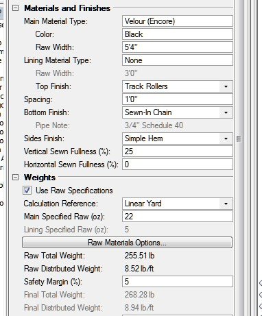
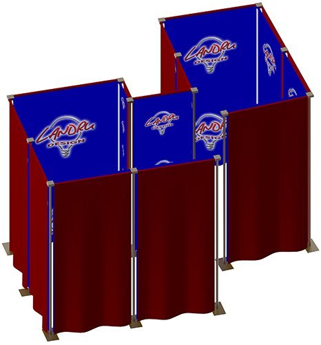
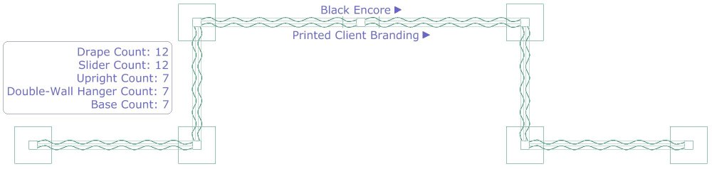
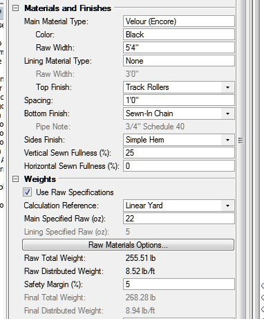
Happy 2021! We trust that you are doing well and that you're finding ways to see “positive” in the new year. Here, every day finds new ways to be grateful for things that were so easily taken for-granted a year ago... If you're like us, you appreciate the "Bottom Line Up-Front" approach. So...here you go: Yesterday we released version 2.5 of SoftGoods 2. If you're already part of the Landru Design tool family you will be receiving upgrade information shortly. If not, you can stop by our VW Plug-Ins page for more info on our tools. Now, for those who like such things, below are some general details about SoftGoods 2 version 2.5. Every one of the things below are in direct response to input from users like you. Is one of your requests on the list? 1) The weight estimating system that was introduced in SoftGoods 2 version 2.3 has been significantly refined. For example, the raw material specifications used by the tool to calculate Total and Distributed Weights are now managed through the “Raw Materials Options” dialog, allowing you to edit them on-the-fly. 2) You can now use SoftGoods 2 to create double-wall Pipe-and-Drape runs. You’ll find that all of the familiar "single-wall" 3D options are separately specified and applied for each wall. Also, the tool accounts for the limited slider hanging points of the real-world hardware. 3) The Pipe-and-Drape mode now offers additional hardware options, allowing you to do things like model layouts in which Pipe-and-Drape is to be placed along walls or situations in which uprights and/or bases are not used. These new features will also help you in easily placing secondary Pipe-and-Drape runs on other runs’ bases. 4) The SoftGoods 2 3D Options system has been improved. You can now specify hardware color and textures that used to be hard-coded. Also, the approach for specifying "By-Class"-driven textures has been greatly simplified. 5) The SoftGoods 2 embedded text functionality has been expanded. Adding to the "Bubble and Leader Line" and "Round Off Dimensions" features introduced in the last release, new Pipe-and-Drape labeling is included, allowing you to label drape "sides" and/or double-wall drape lines. 6) The SoftGoods 2 Object Information Palette has been refined. In addition to new fields being added ("Sandbags," "Drape Clips," "Pipe Note," "Container ID," "Vendor," and "Cost"), if you use Vectorworks® 2021, you’ll have the ability to “collapse” parts of the OIP you may not often use. If you'd like more detailed information, you can download a copy of the manual, HERE. We hope you are as excited about the new features as we are!
-
Well-explained... 3 things: There is no reason to delete the XML file in the main Application folder. In fact, once you've added any elements to the tools' Library/Catalog, the tools ignore that file and use one placed in your User folder. And, if you delete the XML file in your User folder, you'll lose any elements you've already added. Changing the Units to mm only applies if a) the "source" Symbols were created using an out-dated Record format (w/o Units) - or, if the Symbols were never updated to the current format - and b) mm were assumed when those Symbols were created. (The Record format version issue is where 99.999% of users have problems.) Both the 2021 version of the tools and the Landru Design version (for any VW version 2018 or newer) give you the option of inserting Symbol geometry directly in addition to or instead of adding Symbol data to the Library/Catalog.
-
Speaker tool second bumper
C. Andrew Dunning replied to gmulder's question in Wishlist - Feature and Content Requests
No question. This one is on The List. 😉 -
Speaker tool second bumper
C. Andrew Dunning replied to gmulder's question in Wishlist - Feature and Content Requests
You can add additional bumpers. Simply select the bumper instead of one of the speakers in the "...to Add" List Browser in the "Array" tab of the Config dialog. The 1 caveat is that the main bumper and the additional bumpers will all be the same type. We don't have a secondary type yet. Until we do, a way to "trick" the tool is to use bumper geometry as 1 of the 3 speaker types. -
Speaker Array-Symbolname disappear in Worksheet
C. Andrew Dunning replied to Tom M.'s topic in Entertainment
My pleasure. Feel free to ring back w. any other questions... -
Speaker Array-Symbolname disappear in Worksheet
C. Andrew Dunning replied to Tom M.'s topic in Entertainment
This isn't a bug. When Speaker PIO objects have Tilt values other than 0, the Symbols contained in the PIO "wrapper" are no longer seen as Symbols by the rest of Vectorworks - and, therefore, by the Worksheet system. So, your best bet will be to create a Worksheet based on Speaker instances instead of Symbols. Does that make sense and/or help?- 3 replies
-
- 1
-

-
- speaker array
- workseet
- (and 1 more)
-
Use the LED Screen tool (or, our VS4-LED) and choose the "Vert. Strips" "Base Structure."
-
Speaker Array - Rigging Frames & Pull-Back Bar
C. Andrew Dunning replied to Mark Aceto's topic in Entertainment
100% my pleasure!- 23 replies
-
- 1
-
-
- speaker
- speaker array
- (and 1 more)
-
Speaker Array - Rigging Frames & Pull-Back Bar
C. Andrew Dunning replied to Mark Aceto's topic in Entertainment
Bingo!!- 23 replies
-
- 1
-
-
- speaker
- speaker array
- (and 1 more)
-
Speaker Array - Rigging Frames & Pull-Back Bar
C. Andrew Dunning replied to Mark Aceto's topic in Entertainment
Mark - The "LYON-W" Symbol (the one NOT including the pull-back - in the file you sent) contains both Generic Solids and the embedded "Rigging Frames" Symbol. It is that Symbol that is causing issues. As to "non-Hybrid," the tools should throw errors w. that...