Matt Panzer
-
Posts
3,328 -
Joined
-
Last visited
Content Type
Profiles
Forums
Events
Articles
Marionette
Store
Everything posted by Matt Panzer
-
Nice rendering Phil! The image (along with a chance of free samples) makes me want to visit there. :-P Alan, Thanks. You're right. There are so many ways to do things in Vectorworks and sometimes we get caught up in more complex approaches when there's a much simpler way. What's "obvious" to one user is not always to another.
-
Glad to help Phil! BTW: The bottom of the wall can also be reshaped if needed.
-
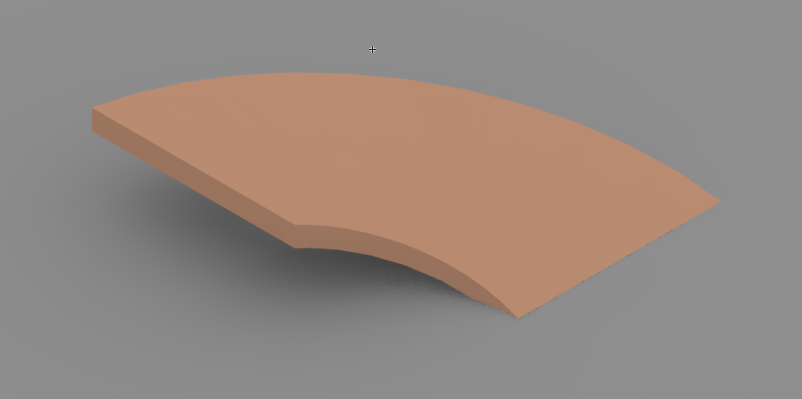
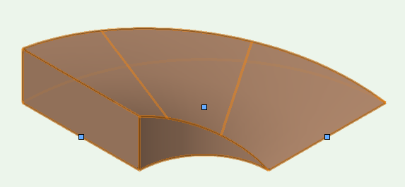
Hi Phil, You could try creating a 500mm wide x 200mm tall round wall, then use the reshape tool to bring one side down to zero.
-
Hi Alan, The drawing numbers cannot be moved separately from the marker. You might be able to get rid of them by creating your own custom marker symbol by placing it in a VW file in the 'Interior Elevation Marker' folder located in the Library/Defaults folder within your VW user folder. I have not experimented with this but it might be worth a shot. Probably the easiest way to approach this is to copy the VW file (in the same location within the VW application folder) to the user folder location and modify it.
-
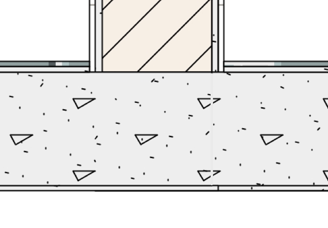
I see. I'm guessing you cannot use one continuous slab. This would also require a patch in the annotations. Probably the easiest way to patch this is by using a line thick enough to cover the line between them and set the color of the line to match the gray fill of the concrete hatch. While this will also create a small break in the lines within the hatch, it shouldn't be too noticeable. I realize that this is not an ideal solution and these are situations we'd like to improve upon.
-
I assume you're talking about joining a slab component to a wall component in order to have (for example) wall board run down to and under the bottom of a slab with no seam? This cannot be done without adding a "patch" in the viewport annotations.
-
RJR, You'll need to create a new Vectorworks file in your Vectorworks user folder. Alternatively, you could copy the desired "Symbol Posts" file from the Vectorworks application folder to the same location in the user folder. You can then add and delete posts symbols from the file in your user folder as you wish.
-
This is because a 2D object is always extruded vertically so the wall feature object can make decisions on how cavities can wrap around it. A 3D object could have much more complex geometry so the wall feature will only assign the geometry to one cavity with no component wrapping.
-
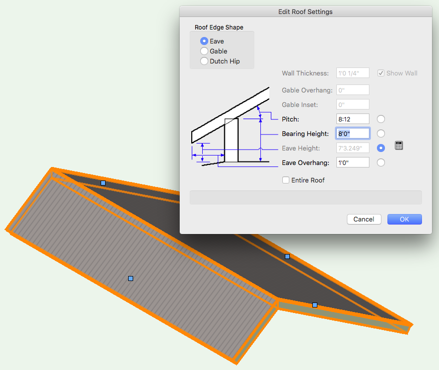
The roof object can also do this easily: Create a roof from a rectangle Change the settings on the two opposite sides to be gables Set the bearing height of one of the sloped faces the the desired height (above the other).
-
These are wall component wrap controls. It sounds like your wall has no components so the popups only display "none". The popups allow control over how the components wrap (or don't wrap) around the wall feature.
-
Hello RJR, Are you sure you placed the file in the correct location? I created a new post symbol in a VW file and placed it in the following location and it shows up in the Railing/Fence Settings: /Users/<YourUserName>/Library/Application Support/Vectorworks/2017/Libraries/Defaults/Railing Fence/Post Symbols.vwx
-
Hello RJR, I think what Markvl is saying is that you don't see the thick lines in Vectorworks because you don't have Zoom Line Thickness turned on. This setting only effects the screen display to give a more accurate preview of how it would print/export. Exporting always uses the line thickness. Try turning Zoom Line Thickness on and see if the lines in Vectorworks looks more like the export. If so, this will confirm that you need to adjust your line thicknesses in your wall and slab styles.
-

Converting 3D object to lines results in 3D lines
Matt Panzer replied to MHBrown's topic in General Discussion
I'm not seeing this behavior. What type of object are you converting to lines? Can you upload a simple file that demonstrates this? -
Hi Alan, Interesting. I have not seen that in the file. However, I just noticed the wall breaks at the ends of the beam instead of at the end of the storefront frame. Christian, I'm not sure if you fixed this, but it can be fixed by placing two loci (in the symbol definition) to define the ends of the wall break. In this case, you should have the loci located where the wall should meet the storefront.
-
I thought that might be the reason for the 1:1 scale, but I though I'd explain all that in case. ;-) No problem for the help. I'm glad it was helpful! You have a good weekend as well. Best, Matt
-
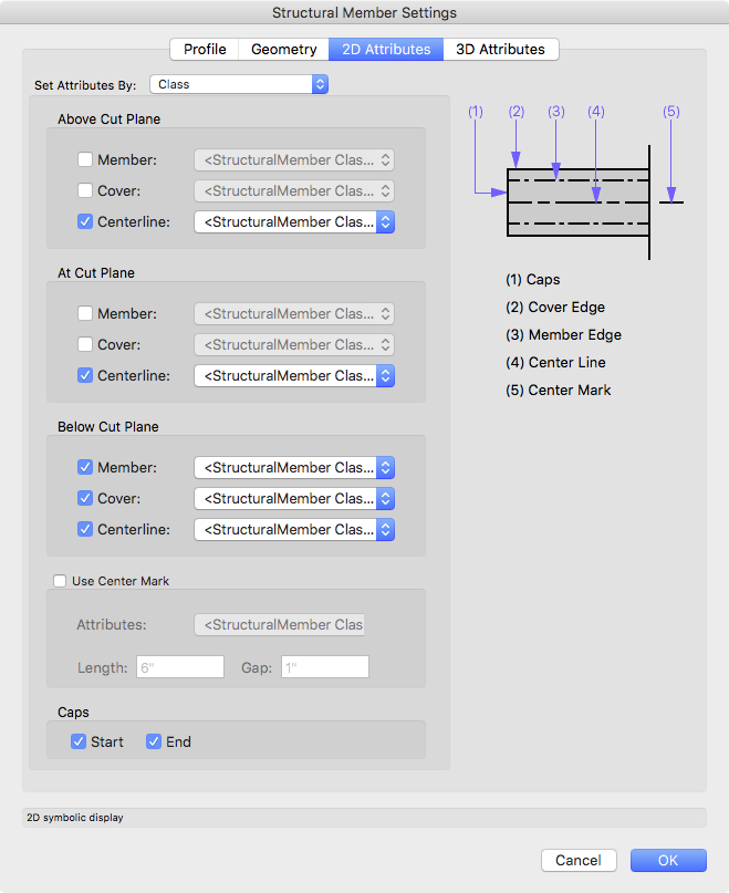
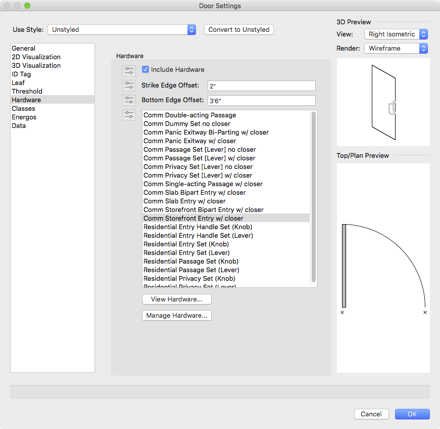
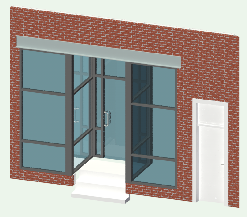
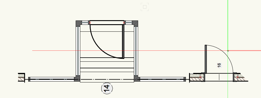
Christian, I made a few changes to get what you needed. But first: I noticed that the design layer scale is set to 1:1. While some VW users do this, I find it best to set it to a scale you plan to use for the typical floor plan. Usually 1/4" = 1' (imperial) or 1:50 (metric). This give you more WYSIWYG graphics as you work on the plan. I changed the design layer scale in the attached file. Keep in mind that the scale is not changing the model but only how it's displayed. This allows the line weights and line styles and other graphics to show as it would be printed at that scale. This is what else I did to the file: 1. created a new "Structural-Beam" class and gave it a dash-dot line style 2. Placed the Structural Member object in the Structural-Beam class 3. Selected the Structural Member and edited its 2D Appearance settings (via the Setting button in the Obj info palette) as shown in the attached screenshot. This gave the beam a dash-dot line for the centerline of the beam (see screenshot). 4. I then edited the storefront symbol, selected the entry door, and clicked the Settings button in the Obj Info palette. 5. In the Hardware pane of the dialog, I chose the handle for the door (see screenshot). storefront_in_brick_wall-02.vwx

-
Glad to help! :-)
-
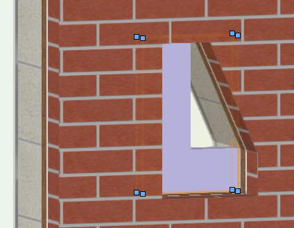
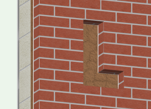
No problem! The 3D Wall Hole Component lets you override the default 3D Wall hole VW gives symbols. When no wall hole component is present, wall holes will cut the hole based on the 3D geometry. This is often enough but can sometimes not give desired results. The hole profile is generated as if you placed a rubber band around the 3D geometry (looking at the face of the wall). This causes problems when you have shapes like an extruded "L" because the "rubber banded" hole will not fill in between the top and bottom right of the shape. The wall hole component let's you get around the problem by inserting 3D geometry that will subtract from the wall. Keep in mind that this geometry will subtract from the wall meaning it can be any complex shape and only the shape will be removed. The example below shows the hole cut geometry located so that it only cuts through the brick component of the wall making a niche.
-
Camera match for product design?
Matt Panzer replied to Kaare Baekgaard's topic in General Discussion
Hi Kaare, Can you send me the file privately? -
Try selecting the window and setting the Break (near the top of the Obj Info palette) to "No Break". This option will still show the outline of the opening in plan views but the wall will continue through. Ideally, you'd have a way to dash the outline in plan views but I have not found a good way to do this. You can, however, place the window in a class that is turned off in plan views. The hole will still show up in 3D views. The downside to this is that you'll need to make the class visible in order to select and edit the window object. Or, there's option B: Create a symbol and insert it into the wall with "No Break". The symbol would have a simple rectangle (with a dashed line and no fill) in the 2D component, and an extrude in the 3D Wall Hole Component. See the attached file. Beam_Pocket_Option_B.vwx
-
Hi Christian, I'd try your option B. Instead of creating an opening and inserting a curtain wall in the opening, I'd try placing the curtain wall in a symbol and inserting the symbol in the wall.
-
Not if you keep looking. :-P
-
This can be done by right-clicking on the unstyled roof and choosing the "New Roof Style from unstyled Roof" command.
-
Right. I think it would be a good thing to separate the 2D and 3D. It might not take a complete overhaul, but it will complicate the interface. This IS on the radar...
-
I will confess that I am no expert on Marionette. So I can be of little (read no) help on this. However,@MarissaFmight have some ideas. :-) Thanks Samuel. Screenshots would be good. Please feel free to send me a VW file privately as well (if you can). The more we have to help us better understand the problem, the better the chances...