


Matt Panzer
-
Posts
3,328 -
Joined
-
Last visited
Content Type
Profiles
Forums
Events
Articles
Marionette
Store
Everything posted by Matt Panzer
-
Thanks for the file. Something certainly went wrong with the dormers in the roof. the only thing I could do is to edit a roof face and causing the dormers to be deleted. My recommendation is this: 1. Edit a face of the roof to reset it and lose the dormers or (probably better) recreate the roof to be sure there's no gremlins lingering. 2. Create the dormers "from scratch" by placing your own walls, windows and roofs. The built-in dormer feature is pretty limited and best for quick conceptual generic dormers. I think you'll find it far easier to create a dormer to your specs with walls, windows, and roof objects. Once it's in place, you can cut a hole in the main roof by creating a polygon and using "Clip Surface" with the polygon and roof selected. I've attached your file with the one dormer started to give you an idea of how it can work. I hope this helps! -Matt Roof_Dormers_v2017.vwx
-
Can you attach a small file with the roof so we can have a look?
-

Tips for using Line End markers on the design layer
Matt Panzer replied to Andrew Davies's topic in General Discussion
No problem Andrew! just keep in mind that working the design layers is not WYSIWYG with these options. -
Tips for using Line End markers on the design layer
Matt Panzer replied to Andrew Davies's topic in General Discussion
Hi Andrew, If the only place you care to see the markers is in the viewport, change the marker scaling as needed in the viewport's Advanced Properties. -
Rotating a symbol around it's insertion point
Matt Panzer replied to GVRT's topic in General Discussion
Ha! Now I know why my photo never made it into marketing materials here. ;-P -
Rotating a symbol around it's insertion point
Matt Panzer replied to GVRT's topic in General Discussion
LOL! Nice job Raymond! However, Mike looks a little pale... -
Right. It's now coming back to me. :-) I don't believe there's a way to do this without sheet layer viewports. The reason why Design layers export out at 1:1 is because the objects contained on them are exported to model space in DWG files. Model space is fixed to 1:1 and cannot be scaled. Sheet layer viewports help because they export to DWG as viewports (that can have a scale). I'll look into some things and let you know if I find anything out.
-
Unfortunately, the plug-ins use deprecated dialog calls that current versions of Vectorworks no longer uses. While it wouldn't be that difficult to update the code, it could take some time and there's a good change other issues will surface. We've probably talked about this before, but can't you use the Publish command to export Saved Views as DWG files?
-
You're welcome! Glad to hear you're on the right track! Best, Matt
-
Just to clarify: You grouped the viewport and resized the group, then ungrouped to return to the viewport? Then you entered the viewport annotations and the Camera Match object is missing, or is something else wrong?
-
Thanks for sending the files. Here's what I found: In order to get PDF files from VW, your workflow was to copy the viewport and create a "new document from clipboard" in Apple Preview. This is a neat trick to get practically anything from an application into PDF form, but it can also be unpredictable in getting the desired quality your after. What also made the files especially large was because the viewport size was 5'4" x 48". Multiply that by the seemingly low 72 DPI still makes for a big image file. I think the best, most predictable approach would be the following: Set the page size to the size you'd like for output. Set the Sheet Layer's DPI to the resolution for output. Set the scale of the viewport and crop it (if desired) to fit the page. Use the Export Image or Publish command to export the image as a PNG (for maximum quality but larger files) or JPG (allowing you to control the quality vs file size for potentially much smaller files). Note: set the DPI in the Image Export settings to match the Sheet Layer DPI. This method will give you far better and consistent results in getting images out of VW. As for combining them into a PDF, you should be able to do this in Apple Preview: Open the first image Click on the small popup menu in the top left of the document window and choose to show "Thumbnails" Drag other files into the thumbnail sidebar Save as a PDF
-
This is hard to say without looking at the file. Is it possible to send it to me privately?
-
2017 Camera Match (more than one object)
Matt Panzer replied to HEengineering's question in Troubleshooting
Great! I'm glad it helped get you on the right track. I wouldn't know what to do without my ScreenFlow. :-) -
2017 Camera Match (more than one object)
Matt Panzer replied to HEengineering's question in Troubleshooting
The answer to your question is no. Viewports display the model as a whole - so there's no reasonable way to do it. However, I did get your file and setup what I think you're after. I sent you the VW file privately and including the video here: ScreenFlow.mp4 Please let me know if you have any questions. Best, Matt -
You can right-click on the Window or Door instance and choose the "New plug-in Style from Unstyled Plug-in" contextual command (or select the object and choose the same option in the "Style" popup in the Object Info palette). This will create a new Style with all parameters set to match the instance.
-
Yes. The Column tool (as Kevin suggested) would be best. These objects have both an Architectural component and Structural component. You would only need the Structural component (which can use the steel shapes).
-
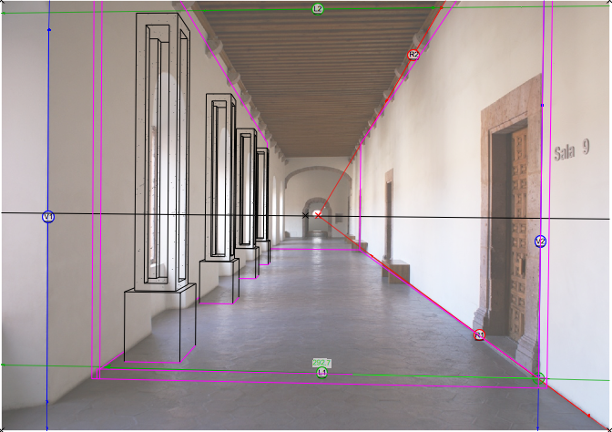
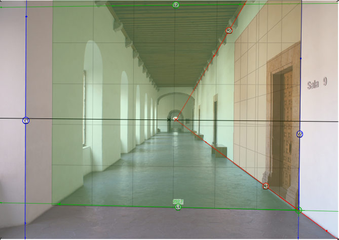
Christiaan is right on all accounts. As he mentioned, using a similar photo but slightly panned to the right or left (so the vanishing point is not so close to the center) will help a lot. I think it's worth mentioning that cropping the photo so that the vanishing point is more to the side will not help because it will not change the actual perspective of the photo. I adjusted the left (green) control lines a bit more, made "L1" the measured line and gave it the same dimension as in the model. Also, if you haven't used the preview object in Camera Match, give it a try. Views similar to one point perspective can be tricky, but the preview object can help. Notice how the right plane of the preview object (below) fits nicely against the right wall. If you slightly move a free control line up or down, you'll notice this plane rotates away from the wall. Using the preview object lets you make slight adjustments until the planes fit the perspective of the photo better. Here's the Camera Match view with a little fine tuning: columna.vwx
-
Hello BG, You are correct. While we're aware of this shortcoming, I encourage you to post this in the Wishlist forum (or@JimW might be able to move this thread there).
-
You're welcome!
-
Have you tried using a wall feature? ScreenFlow.mp4
-
Camera Match Vanishing/Control lines
Matt Panzer replied to HEengineering's question in Troubleshooting
You're welcome! Glad to help. The "point nodes" (AKA control points, grips, handles, etc) are not adjustable. However, the label size on the Camera Match control lines can be adjusted by changing the Font Size of the Camera Match object (in the Text Menu). I think the control point size depends on the monitor resolution? -
Camera Match Vanishing/Control lines
Matt Panzer replied to HEengineering's question in Troubleshooting
Would it be possible to send me the file privately? I'd be happy to have a look. -
Clip Surface command limited to 1,000 Objects ??
Matt Panzer replied to halfcoupler's topic in General Discussion
Here's a file with an extrude using a texture map with transparency and bump maps to create the perforations. Far more efficient than creating all that geometry. :-) Perforated_Metal_Texture.vwx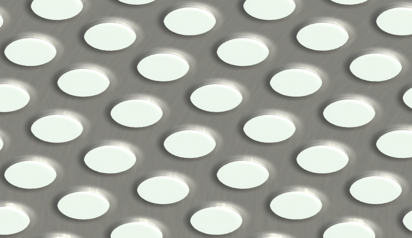
-
Right. While it can be helpful when manually setting up layers for floors of a building, it can also get in the way for other things. I think improvements could be made here. If we were to try to keep a stacking behavior for new layers, I think it would be better to set the new layer elevation to "stack" on top the currently selected layer (in the Organization dialog) instead of the layer with the highest elevation. This would at least allow more control.
-
Hi Jose, Try setting your "Roof_Restautante_Lanzamiento" design layer elevation to match the top of the restaurant walls (33.15m). Then set the bearing height for the roof to 0m. This will get you what you're after. Another option would be to set the "Roof_Restautante_Lanzamiento" to match the floor elevation and set the bearing height based off of that. In that case, you would set the layer elevation to 30.15m and the bearing heights to 3m. This approach is useful if you need to set different bearing heights for different roof faces (based off the floor height).
