Matt Panzer
-
Posts
3,336 -
Joined
-
Last visited
Content Type
Profiles
Forums
Events
Articles
Marionette
Store
Everything posted by Matt Panzer
-
I agree that this could be a little more intuitive. We considered having the catalog item "by instance" in our content to be more convenient. However, we wanted to reinforce the idea that a Door/Window Style typically represents a Door/Window "Type" (or a specific size and model). We recommend importing a style with the catalog item by style and renaming it to refer to a specific "type" (eg: "Window A"). This way you will have a style for each type. While, in the beginning stages of design, users may want more flexibility, we wanted to direct them in the direction that will make it easier to manage door/window "types" as the project progresses.
-
Edit the Style and toggle the By Style/Instance button to "By Instance" next to the catalog button at the top of the dialog. This will allow instances to choose different models from the catalog (via the "Select from Catalog" button in the Object Info palette or Settings dialog).
-

Colour Blind Function
Matt Panzer replied to Jim Smith's question in Wishlist - Feature and Content Requests
To answer my own question: Maybe not in its current state. We would need the ability to choose ranges of color hues and maybe other color settings. -
Colour Blind Function
Matt Panzer replied to Jim Smith's question in Wishlist - Feature and Content Requests
Interesting idea! I wonder... could a DataVis be created for this? -
We made some tweaks for an upcoming service pack that improves how the section cuts are placed in relation to the marker. Until then, the suggestions from @Boh and @Tom W. should help.
-
SECTION VIEWPORT - randomly change to regular viewport
Matt Panzer replied to drelARCH's question in Troubleshooting
OK. Thanks again for the information. We're looking at this but please to let me know if you have any more ideas of what might be triggering it. -
SECTION VIEWPORT - randomly change to regular viewport
Matt Panzer replied to drelARCH's question in Troubleshooting
Thanks for the info. Have you seen the problem in a file that started fresh in VW 2020 or later? I'm wondering if something happened when brining the file forward from VW 2019. -
SECTION VIEWPORT - randomly change to regular viewport
Matt Panzer replied to drelARCH's question in Troubleshooting
Thanks for the file. This is a bizarre one! I entered a bug (VB-178791) with a simplified version of the file for the engineers to look at. If you have any idea what actions may've caused this, please let me know. Best, Matt -
SECTION VIEWPORT - randomly change to regular viewport
Matt Panzer replied to drelARCH's question in Troubleshooting
Can you send me the file privately so I can take a look? -
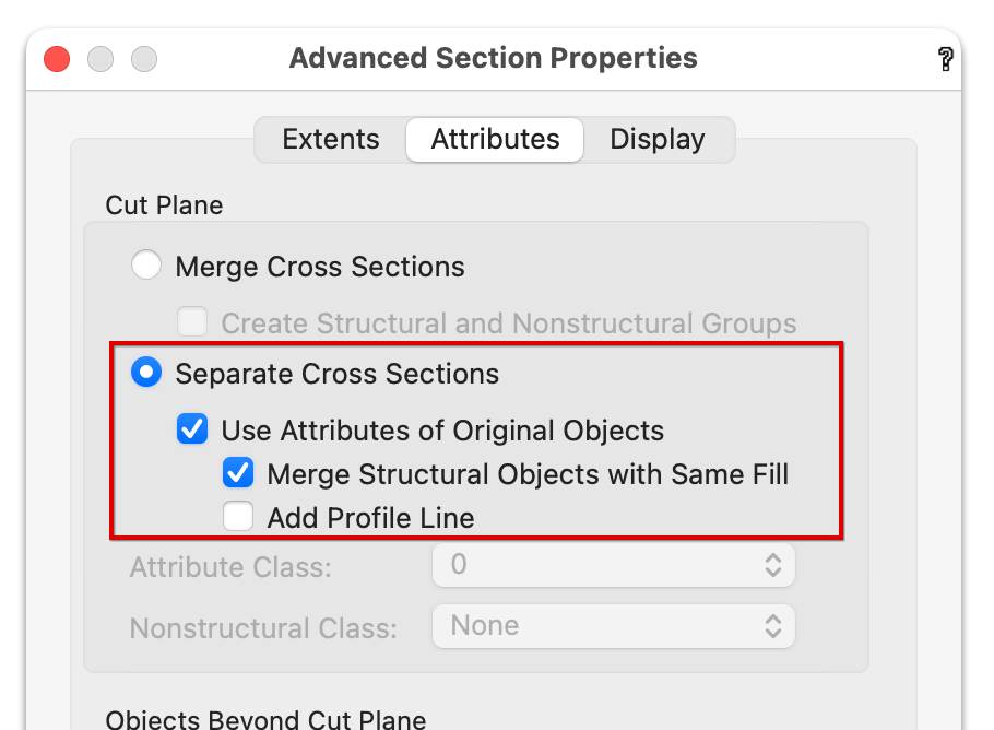
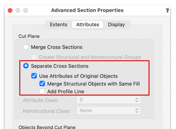
Go the the Advance Section Properties dialog (via the Object Info palette button) and try these settings: BTW: I noticed the window in the wall to the left in the section is not inserted into the wall causing their geometry to overlap each other.
-
As Pat said, please do send the file along with steps to repeat to http://www.vectorworks.net/support/bugsubmit
-
STYLED SECTION-ELEVATION LINES TURN ALL AT ONE POINT TO 'UNSTYLED'
Matt Panzer replied to drelARCH's question in Troubleshooting
Right. That is the big mystery! Played some more trying to make this happen, but I cannot find a way to recreate the problem. I'll keep my eyes peeled for this though. -
STYLED SECTION-ELEVATION LINES TURN ALL AT ONE POINT TO 'UNSTYLED'
Matt Panzer replied to drelARCH's question in Troubleshooting
@drelARCH, Thank you for investigating and explaining this in such detail! From what I see, duplicating a viewport containing a Section-Elevation Line that defines a section viewport should result in the a viewport containing another "defining" Section-Elevation Line. However, copy/pasting or option-dragging a copy of the a Section-Elevation Line will result in one that's "linked" to a viewport but not defining one. A way to tell the difference is to select one and look at the Linked Viewport popup in the Object Info palette. If the popup is displaying the name of a viewport and is disabled, it's defining that viewport. If the popup is displaying the name of a viewport and is enabled, it's linked to (but not defining) that viewport. -
Window Objects Not Showing Jamb Line in Round Wall
Matt Panzer replied to KenAB94662's question in Troubleshooting
Thanks for the file. So this looks like a bug in Vectorworks 2020 that has been corrected in Vectorworks 2021. However, this case can be corrected in 2020 by selecting the windows and settings the "Break" to "Full Break with Caps" in the Object Info palette. -
Window Objects Not Showing Jamb Line in Round Wall
Matt Panzer replied to KenAB94662's question in Troubleshooting
@KenAB94662, Can you copy and paste the straight and round wall (with windows) into a new vectorworks file and attach it to this thread so we can have a look? -
Problem with 'Add 3D Object to Slab...' command
Matt Panzer replied to Tom W.'s question in Troubleshooting
Hi Tom, I do not know why the problem is happening and I was able to recreate the problem. Bug reported (VB-178449). -
STYLED SECTION-ELEVATION LINES TURN ALL AT ONE POINT TO 'UNSTYLED'
Matt Panzer replied to drelARCH's question in Troubleshooting
Unfortunately, without a reproducible case, there's little we can do. I just experimented with the workflow you described but was not able to recreate this problem. Please let us know if you discover any more clues. -
Right. Section-Elevation Line instances can only be placed in regular Top/Plan viewports and Horizontal Section Viewports.
-
You're welcome! If you select a Section Viewport and click on the "Section Line Instances…" button in the Object Info palette, you will be able to select which viewports to display instances of the Section-Elevation Line.
-
OK. I got your file and took a look and found two different reasons why some grid lines weren't showing: One grid line (#8) was not perfectly perpendicular to the cut plane. The other grid lines (B - F) are completely behind the cut plane causing them not to be seen by the section viewport. They need to be passing through the cut plane or completely beyond the cut plane in order to show. ScreenFlow.mp4
-
@simona, Can you the file privately in a message addressed to both @Wes Gardner and @Matt Panzer ?
-
STYLED SECTION-ELEVATION LINES TURN ALL AT ONE POINT TO 'UNSTYLED'
Matt Panzer replied to drelARCH's question in Troubleshooting
Right. Vectorworks should ask you before deleting resources from the resource browser. Purge should only delete unused styles, so I doubt that is the issue. However, if you see otherwise, let us know. -
Grid Line with Bubble at Both ends won't show on sheet layer
Matt Panzer replied to Coast and Beam Architect's question in Troubleshooting
I cannot reproduce this issue. Is the "Show Bubble at" setting setting for the Grid Lines in the viewport set to "Both Ends"? Can you send me the file privately so I can take a look? Please include the exact steps you take to create the viewport. -
STYLED SECTION-ELEVATION LINES TURN ALL AT ONE POINT TO 'UNSTYLED'
Matt Panzer replied to drelARCH's question in Troubleshooting
Hi @drelARCH, I have not heard of this issue before and don't see any bug reports on it. It sounds to me like something caused the style resource to be deleted from your file. When a style resource is deleted, all instances of the style will become unstyled. Is there any chance you may've deleted it by accident? The only other thing that comes to mind is if the Purge command somehow deleted it. If you have any other ideas of what actions lead up to this happening, please let me know. So far, I have not been able to reproduce the issue. -
Hi Simon, Could you use a drawing Label that displays the Sheet Number and keep track of them instead?