Matt Panzer
-
Posts
3,328 -
Joined
-
Last visited
Content Type
Profiles
Forums
Events
Articles
Marionette
Store
Everything posted by Matt Panzer
-

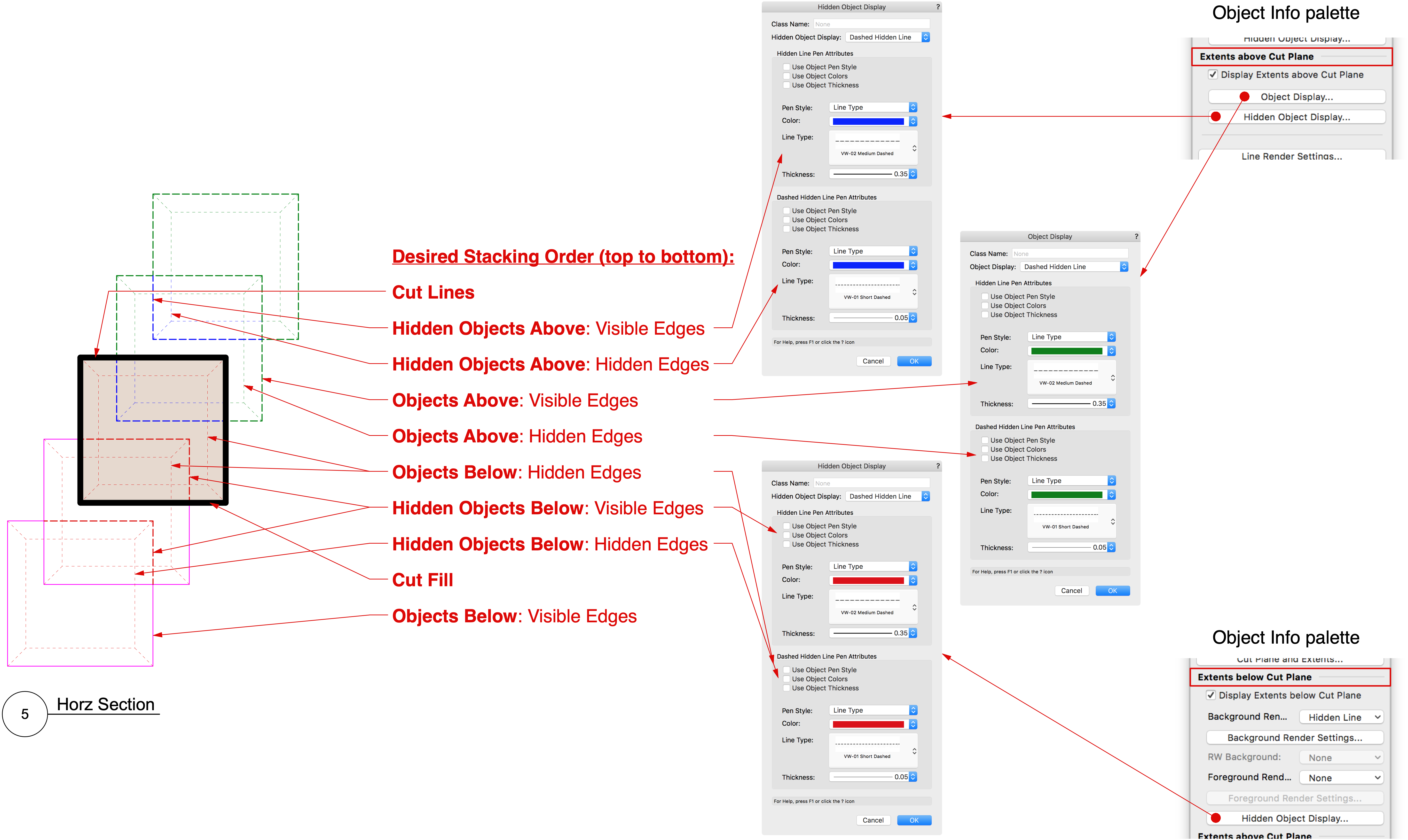
Hidden Object Display settings in Section + Interior Elevation Viewports
Matt Panzer replied to Tom W.'s question in Troubleshooting
That setting is how you want to render each object in that class unto itself. In most cases, you probably only want to see the object as rendered in Hidden Line so you see only visible edges facing the cut plane. Dashed Hidden Line will show the back faces (hidden edges) of each object in that class. When the "Display" setting is not set to "None" the setting will override the Background Render setting (if different). However, if the background Render is "Dashed Hidden Line" the dashed pen attributes of the render mode will be used. The only difference the Background Render setting will make is that setting it to "Dashed Hidden Line" will cause the hidden edges of objects and hidden objects beyond the cut to use the dash line attributes defined in the render settings. Typically, you would want to use a Render Background of "Hidden Line" because these Object/Hidden Object Display settings provide much more control. I agree about the terminology confusion. It stems from the existing "Hidden Line" vs "Dashed Hidden Line" terms. As you know, "Hidden Line" render means the back face edges are not shown and "Dashed Hidden Line" means they are shown. The terminology is not explicit enough in stating to "show" or "not show" these edges. It's not that hard to grasp when you have them as just two settings for a viewport render mode, but expanding it like we have has compounded the problem. -
-
Hidden Object Display settings in Section + Interior Elevation Viewports
Matt Panzer replied to Tom W.'s question in Troubleshooting
I tracked down a graphic that I think will help explain these settings: Model: Five tablets with tapered faces always facing away from the cut plane. Horizontal Section showing various settings: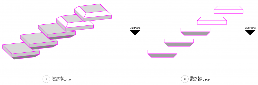

-
GRID LINE TOOL VW 2021 DOESN'T STAY ADJUSTED
Matt Panzer replied to Liene Cikanovica's question in Troubleshooting
I'm seeing similar issues as well. I believe (by design) the Grid Lines should reset after reshaping the crop, but the other settings should not. Bug submitted: VB-177237 -
Maybe try duplicating the style in the Resource Manager and change the text size as you need. You could create a few styles with common variations of text sizes. Then, you can replace the style of drawing labels in your document with these styles as needed.
-
Hidden Object Display settings in Section + Interior Elevation Viewports
Matt Panzer replied to Tom W.'s question in Troubleshooting
Yes. They definitely worked in 2019. -
Section Viewports Object Display settings
Matt Panzer replied to markdd's topic in General Discussion
The feature was added in VW 2019. It looks like the per object issue happened in some VW 2020 version. -
Hidden Object Display settings in Section + Interior Elevation Viewports
Matt Panzer replied to Tom W.'s question in Troubleshooting
Hi Tom, To tag someone start start typing their screen name beginning with "@" My name would be "@Matt Panzer". To answer your question: I was beginning to put something together to show you and discovered a bug in the per object overrides for Object Display and Hidden Object Display in section viewports. The viewport setting work, but not the per object overrides. I just submitted a bug report for this (VB-177006). -
VW 2021 update - Loosing Tiles in Slab makeups in section
Matt Panzer replied to Elise Wilkes-Brand's question in Troubleshooting
This is a known issue and we have a fix in place for an upcoming service pack. -
Slab drainage - how to change slopes values.
Matt Panzer replied to Grzegorz Krzemien's topic in Architecture
I wish I had a solution for you but I do not. The problem is, when connecting drains, other valleys from the drains are removed. In this case, all valleys defining the slopes on the slab are removed leaving you will no control over the slope. I'd like to see a way to set the slope of faces and I know others have wished for this as well. That would certainly help us in this case. Sorry I don't have a better answer for you. -
I played around with your script and cannot find any trick to fix it. I think we may need to wait for a fix.
-
Migrating vw2018>2021: section problems
Matt Panzer replied to line-weight's question in Troubleshooting
I just submitted a bug report on this: VB-176976: Association lost between Section-Elevation Line and its viewport after renaming viewport via script -
I just submitted a bug report on this: VB-176976: Association lost between Section-Elevation Line and its viewport after renaming viewport via script
-
Migrating vw2018>2021: section problems
Matt Panzer replied to line-weight's question in Troubleshooting
I never knew that was a thing... I can do this when I right click the marker object where I've copied it to the design layer of a new file. I don't seem to get that option when I right click it in its original position - in the annotations of a viewport in the original VW2018 file. You're right! In any case, I would advise against editing the path of that object that way - for obvious reasons. 😉 -
Migrating vw2018>2021: section problems
Matt Panzer replied to line-weight's question in Troubleshooting
Thanks for the file. I see the problem as well and submitted a bug for it. This seems to be an odd case and I thinking it may be due to it being flipped in the 2018 file. OK. It looks like the path of the Section-Elevation Marker in VW 2018 was moved from the object's origin. You can see this by (in VW 2018) right-clicking on the object and choosing the "Edit Path" context menu command. When in the Edit Path mode, if you select the polygon, you'll its coordinates in the Object Info palette are (3439, 0). Changing it to (0, 0) fixes the issue. I'm not saying you should do this because it'll shift the object in your VW 2018 file. But, if you were to do this and save the file, the object will import correctly in VW 2021. Now that we know this, we can look into a way to handle these cases. -
Migrating vw2018>2021: section problems
Matt Panzer replied to line-weight's question in Troubleshooting
I see, thanks for the explanation. It would perhaps be overcomplicating things and/or not technically feasible but it would be nice if it's something the user could switch on or off. If I'm on a sheet layer with loads of viewports and complexity then I'll prioritize speed. However, if I'm on a less complex sheet layer, say an A3 sized page with just a couple of viewports, then it would be nice to keep the line thickness zoomable because it feels a bit visually jarring to me, if say, I'm looking around a sheet layer to check that everything looks right before I export it to PDF. Yeah. I certainly understand the jarring issue. It might be worth putting a request for VGM Zoom Line Thickness support (or a quick way to toggle to/from Best Performance) in the Wish List forum so it gets more attention. We have a lot of other things going on in this thread. 😉 -
Migrating vw2018>2021: section problems
Matt Panzer replied to line-weight's question in Troubleshooting
Regarding the Zoom Line Thickness going away during pan and zoom: This is due to the Vectorworks VGM being leveraged for faster navigation (panning and zooming). While the VGM makes navigation much faster, it does not support Zoom Line thickness while navigating. -
Migrating vw2018>2021: section problems
Matt Panzer replied to line-weight's question in Troubleshooting
Thanks for the file. I see the problem as well and submitted a bug for it. This seems to be an odd case and I thinking it may be due to it being flipped in the 2018 file. -
Migrating vw2018>2021: section problems
Matt Panzer replied to line-weight's question in Troubleshooting
I was thinking a VW 2021 file but a VW 2018 file would be better. Thanks. -
Migrating vw2018>2021: section problems
Matt Panzer replied to line-weight's question in Troubleshooting
Can you copy the Section-Elevation Line into a new blank document and attached it so I can have a look? -
Migrating vw2018>2021: section problems
Matt Panzer replied to line-weight's question in Troubleshooting
Yes, I was. Ok. Thanks for confirming. I'm looking into whether this is a bug or a consequence of more recent speed improvements we been making for navigation graphics. -
Migrating vw2018>2021: section problems
Matt Panzer replied to line-weight's question in Troubleshooting
OK good. We do know of an odd case that sounds related to this. Great! Thank you! I'll see if I can find anything on it but I think tech support needs to create an official bug report first. Thanks again! -
Migrating vw2018>2021: section problems
Matt Panzer replied to line-weight's question in Troubleshooting
returning to this: 1. seems to work; it sorts out the displaced text (although the marker line ends up in the wrong place). I can just create my desired style and then apply it to all of the markers, and relocate them. A bit tedious but it works, and it looks like the new objects are better behaved than the old ones (which were always really awkward to resize). So the actual endpoint of the section stays in the correct place, but the marker is shifted? If so, it's probably due to the line in the marker being in a different location than the marker from the legacy object. Once you choose the folder, it creates a style in the Resource Manager and that style is applied to the selected Section-Elevation Line. From there, you can edit the style to correct the shifted text in the Marker Layout. Once you correct that, you can apply the style to the other Section-Elevation Lines. This method should not cause any shifting since you will using the marker layout created from the legacy object on import. -
Migrating vw2018>2021: section problems
Matt Panzer replied to line-weight's question in Troubleshooting
Can you send me a small file and the script that demonstrates this problem? -
Migrating vw2018>2021: section problems
Matt Panzer replied to line-weight's question in Troubleshooting
@line-weight, @zoomer, If you can send me a Vectorworks file from VW 2020 or earlier and tell me which viewports shift, I can put a VB in for it.