Benson Shaw
-
Posts
4,317 -
Joined
-
Last visited
Content Type
Profiles
Forums
Events
Articles
Marionette
Store
Everything posted by Benson Shaw
-
Outdoor Brick or Concrete pedestal for School Mascot (Ram)
Benson Shaw replied to The Hamma's topic in Site Design
I agree w/ @mike m oz and @line-weight. Design will require engineering and probably lots of discussion among client and design team members regarding goals and how to reach them: restoration practices, strategies to prevent future degradation and damage, public safety, structural integrity, lighting, access, etc, etc. Not much definitive offered here. But here are some questions and thoughts, and a concept common for anchoring 4 legged statuary. Curious about: Why is sculpture no longer on its plinth? Intentionally moved to ground for repairs? Vandals knocked it off? then someone moved it upright on the lawn What was the original connection of sculpture to plinth? No apparent anchor points in top of plinth. Sculpture material? Looks like fiberglass where horns are broken. Site is Public property? Private property? Is planned new location a controlled environment? or accessible by public (vandals) 24/7? Some comments and an anchor concept common in public art Sculpture restoration Those horns are vulnerable, especially to “testing” (if I can flex it, maybe I can break it!) and to trophy hunters (Battery saw, 10 min or less if fiberglass.) An internal armature might strengthen agains future breaks. But multiple materials can cause future problems. New connection to plinth - L-Bolts? Sled? Weld feet to a large heavy plate then bolt or anchor the plate to top of plinth? Work with owner and engineer. Make all anchor components stainless or silicon bronze. Isolate anchor system so it nowhere contacts iron rebar (eg plastic spacers or tape wrap at each touch point, use stainless ties, etc.) Plinth design to discourage future damage Taller might keep vandals away. But taller also presents fall and injury danger for those who try. equals liability. If taller, then is fall zone treatment needed, similar to playground regs? Concrete/brick box? Plate atop a narrow column or a cone? Plinth could provide some seating? lighting, planting, etc Location for visibility from many windows. OK, I find this very interesting. @The Hamma, tell us your thinking and how things are going. -B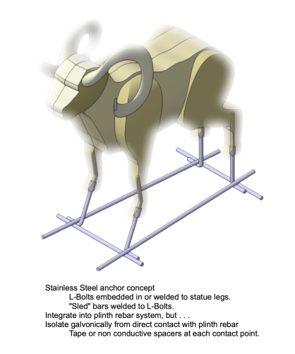
-
Whoa! @Ben Beaumont thanks for reply. So workflow questions. 1. vwx prop line does not adjust to CRS north automatically? It seems to accept drawing x,y. This is perhaps your Convergence??? 2. To make x,y geometry conform to georef CRS, i have a choice: A. Rotate plan via the menu bar feature B. Rotate the georef world via the georef compass tool or the dialog. C. or something else? I’m leaning to B. Notes usa State Plane system divides each of the various states into one or several CRSs. Washington State has 2, a north and a south CRS. Both use the Willamette Meridian as the “Principal” meridian. I’m guessing that Conversion value is proportional to east/west distance from the Principal, and can be translated to a rotational value to match xy north for a smallish project site. (But what if you are working with a regional or international transit system!) This is a dense science!!!!! I know so little but just want my drawings to conform. -B
-
Outdoor Brick or Concrete pedestal for School Mascot (Ram)
Benson Shaw replied to The Hamma's topic in Site Design
@The Hamma Still working on this? Can you post an image or sketch of your goal, with dimensional limits or general scale notes? You need the sculpture? or just the base? Ideas 1] Simple extrude or multi extrude for the base shape. Texture as needed. Image prop for the ram. 2] Model and texture the base. Very simple sideview extrude as placeholder for the ram. Add detail model of the horns. (might try this one, gimme a minute). 3] Image prop for the whole thing if example exists. -B -
Replace 2D component of VW 3D library symbol
Benson Shaw replied to dpkolus's topic in General Discussion
A note about nomenclature: Symbol items in the Resource Manager are symbol definitions. Related symbol items placed in the drawing area are symbol instances. Many of us (I’m guilty of this) use the word “symbol” to mean either one, assuming context sorts the intended meaning. This can also cause confusion. The process required here is to duplicate and edit the symbol definition (in the RM). At least sometimes, using nuanced terminology can help with troubleshooting or explanations of a process. Same applies to styles, sort of a definition or preset for walls, etc. Objects from styles placed in the drawing space can be edited and duplicated and converted to unstyled. But this does not affect the style in the RM. . -B -
.las & .laz import problem with VWX 2023
Benson Shaw replied to Jeff Prince's topic in General Discussion
Confirming: Import fails in vwx v2023sp3 with same error notes as @jeff prince Import succeeds in qgis firenzi Paths to the LAZ file: Opened this, but no joy because could not limit to requested coords/tile: https://apps.nationalmap.gov/downloader/#/ Separate search using tile/coordinate as shown in @jeff prince post. Search term (in DuckDuckGo): USGS Lidar Point Cloud AZ_MaricopaPinal_2020_B20 w0394n3745 Top hit: https://www.sciencebase.gov/catalog/item/624749bad34e21f82763289c Opens to page offering info, thumb of tile extents, & several downloads including this link to LAZ file lower in page. https://rockyweb.usgs.gov/vdelivery/Datasets/Staged/Elevation/LPC/Projects/AZ_MaricopaPinal_2020_B20/AZ_MaricopaPinal_1_2020/LAZ/USGS_LPC_AZ_MaricopaPinal_2020_B20_w0364n3705.laz Downloaded and tried import to vwx and QGIS. HTH -B -
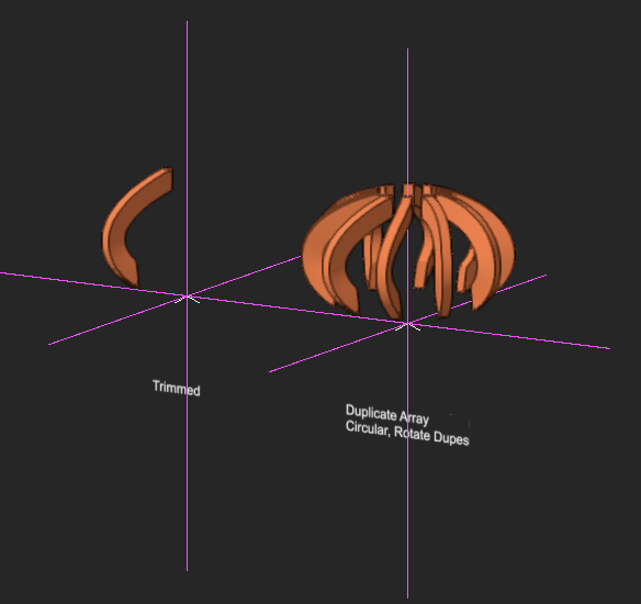
Good if all are from same extrude command. But also need solution for contexts where surfaces are not from extrudes or from same extrusion. This one I traced a poly along bottom edges, Extrude down, Convert to NURBS surface, Add Solids -B
-
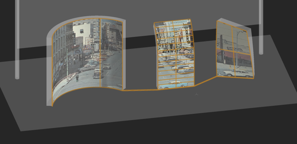
I just tested. For this one, I think the connecters were needed. Middle flat surface accepts texture with different rotation. ???? Switching normals no help. Same with Shell the faces as Solid addition. @Andy BroomellDid you make this one work with only the SA? I have had success with Shell. Extract the multiple faces, then Shell them together at zero or vey thin depth. The Shell, similar to the Solid Addition, is a single, but non contiguous, object which can take the texture as one big image. Didn’t work in this example. Maybe flat to curve is problem. -B
-
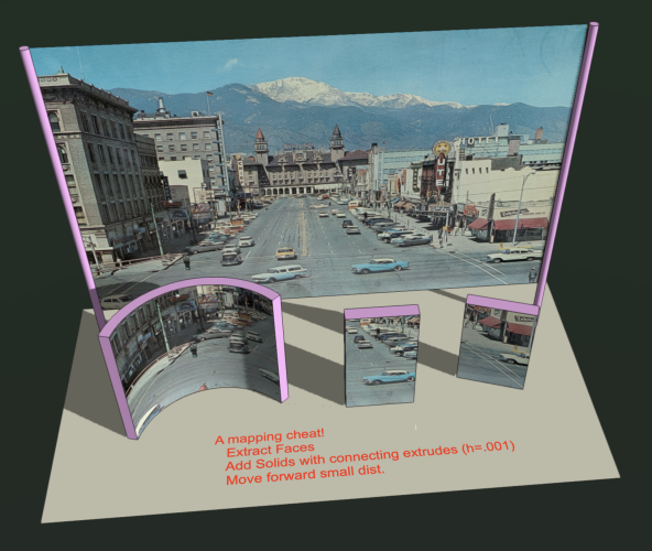
Have not needed this for a while, but thought I would try this cheat again. Mapping to faces of several disconnected objects by converting them to a single object. Back "screen" shows full image texture on a single surface. Foreground objects have same texture mapped to extracted faces: Extracted the front surfaces (created 3 NURBS surfaces) Connected them w/ 2 lines on layer plane. Extruded the lines .001 units. Convert the extrudes to NURBS surfaces. Add solids - creates a single object from the 5 sources. Apply texture > Plane mapping. Orient as needed via offsets. -B 1896549282_TextureAlign2023.vwx
-
DEFORM - Maintain consistent width?
Benson Shaw replied to brandon pass architect's topic in Solids Modeling
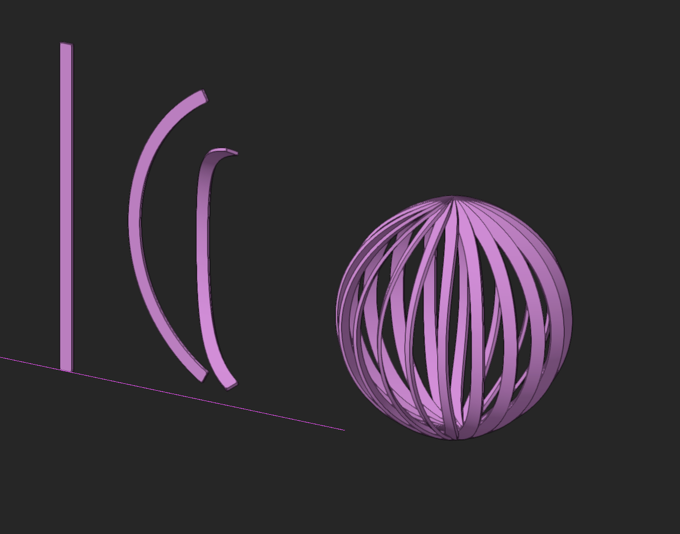
That one provides twist so that face of gluelam is everywhere flush on surface of the spheroid. Another way is to extrude a rectangle as profile of the beam (or one of its boards), then bend twice with deform tool. Eg 1st from front, then from side. Bends will be circular, but will not introduce twist. -B
-
DEFORM - Maintain consistent width?
Benson Shaw replied to brandon pass architect's topic in Solids Modeling
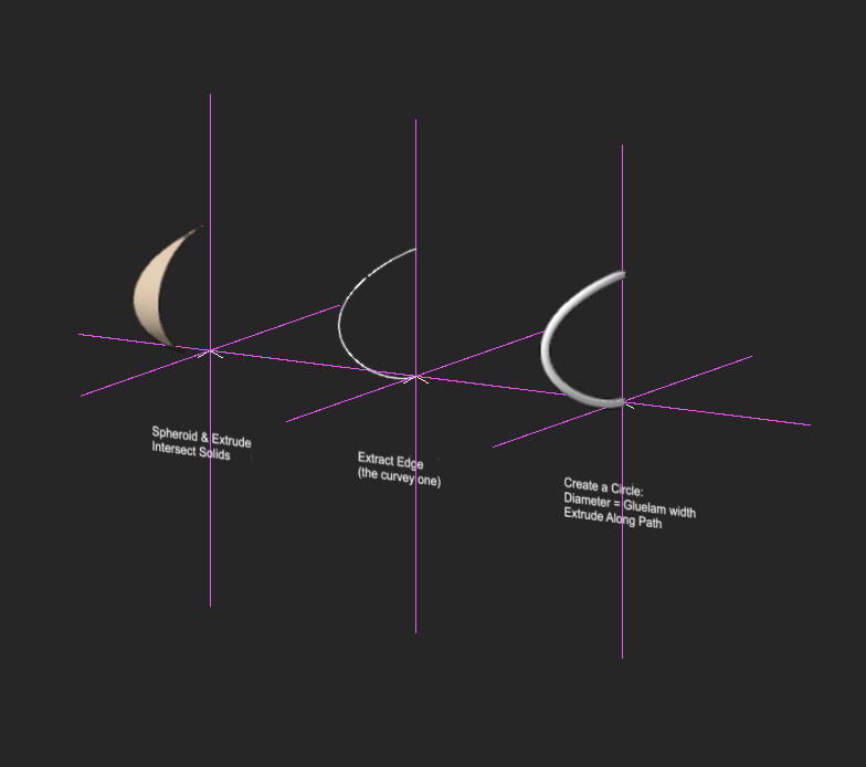
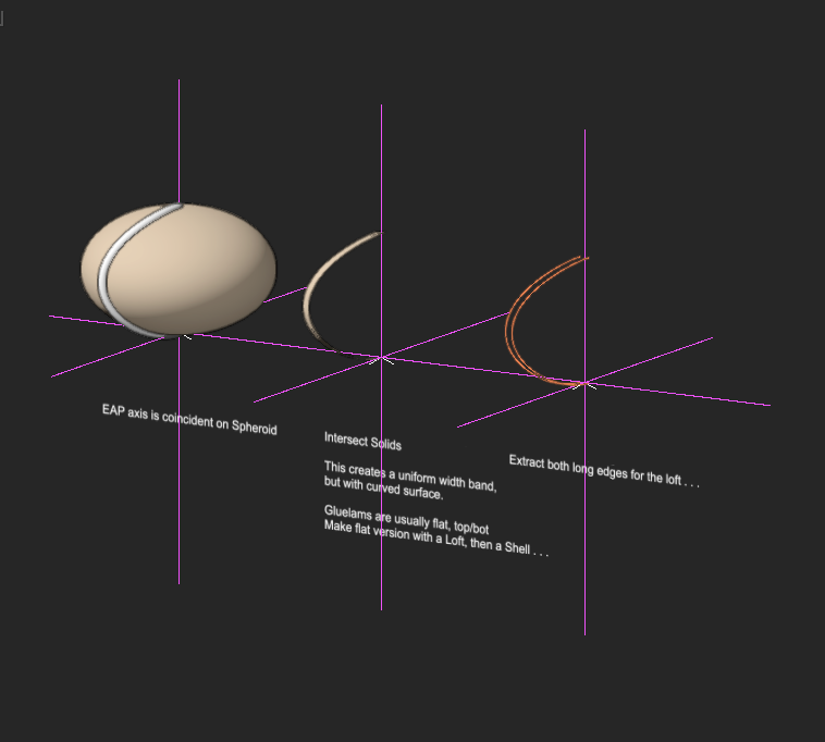
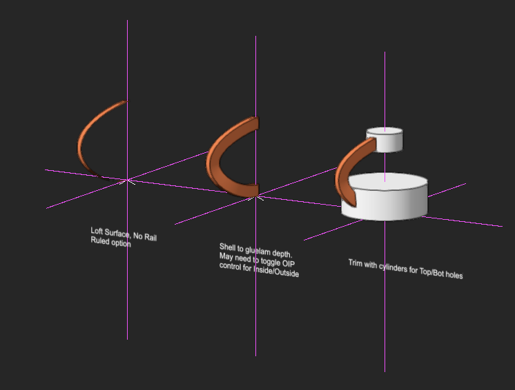
@brandon pass architect I think I understand your goal. Gluelams bend, but not planar, so describe a wandering axis. Here is one way - Start with the final implied spheroid/egg surface. Build up the gluelam shape via several 3d processes limited by the spheroid. Toward the end is a Shell step. I chose full depth of the gluelam. One could instead make repeated shells for each board in the gluelam. File is v2023. Click through the design layers. Ask for earlier version as needed. -B Bent GlueLams.vwx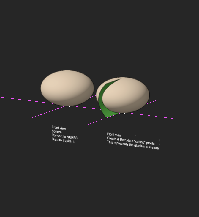
-
DWG file import with multiple lines
Benson Shaw replied to Flair-Studio's question in Troubleshooting
thanks, @Pat Stanford ! I'm glad that purge feature is there and works. I discovered, at least sometimes, a reason for the coincident geometry. This is some form of dwg drawing convention, or office convention, or individual drafter practice which acknowledges 3d or future 3d modeling from the geometry. An example I encountered is lines defining plan view of a concrete curb. The 3d profile includes many edges some of which stack in plan: a top edge, eg next to the wear surface of the sidewalk, paired with the sub grade edge at full thickness of the curb. an edge at top of vertical face of gutter, ie width of the curb. Paired with gutter edge at road pavement surface an edge at street paving surface level representing width of the gutter. Paired with a subgrade edge directly below at full depth of the curb. So 6 lines, stacked in pairs, representing 3 different z values (or more if roadway crowning is represented): Top of Curb, Top of Gutter (or of roadway), subgrade Bottom of Curb. These might be classed separately so that they can be isolated for deletion or view prefs. They might also have z data in the class names or in attached data. Not excusing this, because it is cluttering, annoying and can be confusing. It's not even very helpful for site modeling - level walks, curbs, roads almost never occur. -B -
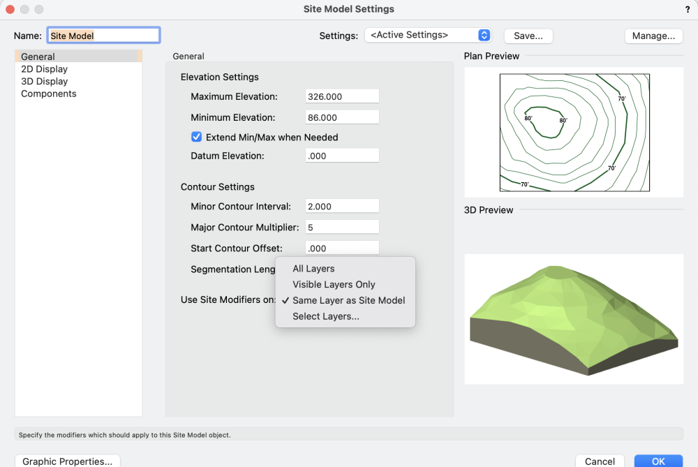
Not sure it is much different from your previous versions. Seems to work mostly as expected for me anyway, with some improvements in 2023. Here is the usual advice: 1st: Be sure to update the Site Model (DTM is easier acronym) to enable any changes (adding modifiers, etc). Click the Update button in the OIP. Usually the DTM will have a red bounding box, and red text in the OIP "Update" button if update is needed. But sometimes no red warning, so update anyway if something not showing as expected. Another thing: Modifier status might depend on layer(s) you place your modifiers. You can configure the DTM to allow or ignore modifiers on certain layers. Select the DTM. In the OIP, click the Site Model Settings button. Click the pulldown menu at Use Site Modifiers on: In the menu, choose something appropriate. The lowest option (Select Layers) offers choices among all the design layers. Post back as needed. Hope this helps. -B
- 2 replies
-
- 1
-

-
- site modifiers
- site modeling
- (and 1 more)
-
Paste & Paste in Place different 10 years ago vs today ...
Benson Shaw replied to Elite Exhibits's question in Troubleshooting
Not sure about version history of the Paste in Place for Extrudes and EAP profiles, but I have at least a vague idea of a couple things that can affect. Not testing right now, so this is from memory. But I think I have experienced a couple Paste in Place surprises in recent versions. One issue is whether the extrude is in original location and rotation when the source profile is accessed. If extracted from orig location, all is good. If source profile is extracted from a moved version of the extrude, the original location may be “remembered” during Paste in Place. Another possible bugaboo involves the drawing status in the extrude Edit pane. It is possible to extract the profile from a working plane determined by 3d view angle when the edit is initiated. This might make unpredictable PIP. Extracting from Layer Plane seems more predictable. Look at the Active Layer Plane pull down. I think it defaults to Extrude #1 or similar. I think that can only be changed to Layer Plane if the drawing is in TopPlan. Copy from Layer Plane in TopPlan might give more predictable Paste in Place. I think??? -B -
Screenshot shows a Fundamentals workspace. Can anyone verify whether Fundamentals license supports pdf import? @AA93 here is a stupid workaround in case your vwx cannot import pdf directly: Open the pdf in other software and save as jpg, png, or other image file. Drag/drop the image file onto the vwx screen, or Import that file via the File>Import >Image file. -B
-
Can anyone suggest a reliable method for 3d scans of venues?
Benson Shaw replied to grant_PD's topic in General Discussion
I’m trying to find a successful path with least effort. Older phone, fewest photos, no extra apps . . . Previous trials with the vwx processing were all failures. Some success with current version is encouraging. Obviously attention during the shoot is required for best results. My question was prompted by the new Apple promotions for their lidar features (eg 3d photogram of chair in sales room brought into interior design model). Has anyone here compared iphone lidar to not lidar images in the vwx photogrammetry offering? @jeff prince ‘s many wonderful examples and his comment from a year ago gave some inspiration to experiment. I think “wave my iphone” is probably metaphorical, and not incompatible with “well taken photos”. Phone cameras compensate very well for lots of waving around error. -B -
Can anyone suggest a reliable method for 3d scans of venues?
Benson Shaw replied to grant_PD's topic in General Discussion
The updated Vectorworks photogrammetry feature actually works pretty well, very well compared to the earlier version (IMHO). Apparently it is based on Apple's API. Load your photos to your vwx Cloud Services and follow the prompts. Results return quickly as several files: USDZ - opens in Apple Preview (and probably many others) as a rotatable 3d image. These are rather heavy files. Several hundred mb. Several PNG files - I believe these are images for texture on the USDZ OBJ - imports to vwx as 3d Mesh MTL - vwx texture file built into the obj Mesh. No need to import it separately as a new texture. mtl is acronym for material, but vwx treats it as a texture. The obj import to vwx automatically adds a texture to the Resource Mgr, but does not add/create a vwx material. As far as I can tell. I'm using an older iPhone, no Lidar. I wonder if the lidar photos would also process to return a point cloud. Heres a recent sample of a concrete stair. It melts in the middle because I was so intent on the sidewalls that I forgot to shoot straight up the middle. -B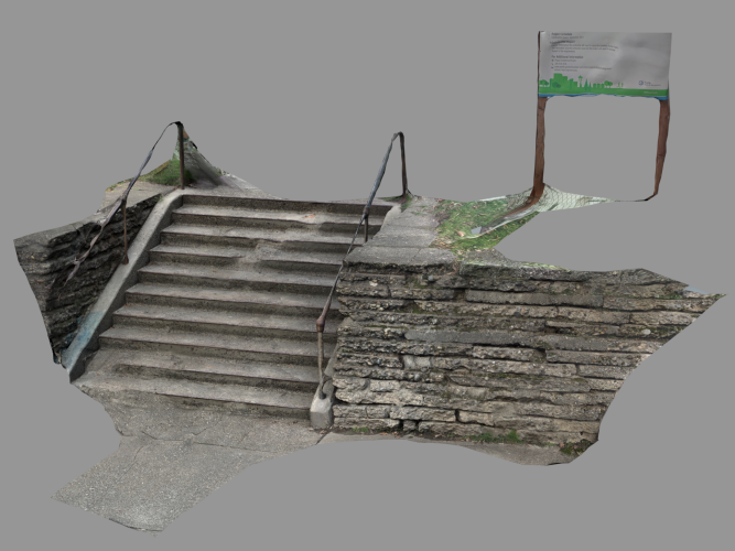
-
Not sure what you mean. In my views the NURBS objects have fewer lines out of place in HL, seem about same in HL preview and Shaded. Wasn't intended as dismissive. Meant to say he is the only responder running Windows. -B
-
Just to verify - File from @AlanW, when I open it, displays same HL problems in same locations as my original file and at least similar to what all you other responders found. But Alan is only running Windows OS. Mac/Window difference? Thanks everyone for testing and commenting! I will put together a bug report. Could be Win/Mac or my original geometry, or ???. We should look for it in other files with HL scenes. Another comment - That HL temporary preview, displays the scene as expected (no anomalies) while the HL render proceeds. I think it is sort of HL lite or Wire Frame Pro so that one can interrupt the render to make edits to view or geometry without waiting for render to complete. then start the render again. I wonder how that preview is different from the completed render, and if it could be a future update feature as additional render mode. -B
-
@Kevin McAllister Thanks, but no difference in the VP. I tried range of smoothing. @AlanW Interesting! Thanks for testing. I saw same at start of HL render, which is a sort of preview while the HL render bumbles along. But when the render completes (about 30 to 60 seconds on my rig), the zig zags return. I edited the extrude to see if any problems there. Only thing I found was an extra poly at central circular medallion area. Deleting that made no difference in the HL. In the Edit Poly pane, I also deleted all the left hand clipping polys and replaced by mirroring the right hand ones. No change in the HL. Also tried to remake from that revised poly in a new blank file. No improvement in the HL. So, I'm still stumped. -B
-
Suggestions? Lost Cause? thx -B
-
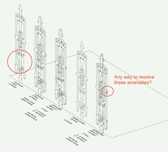
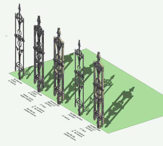
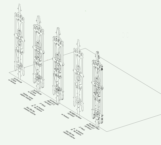
This started in another thread about representing decorative wrought iron. The modeling and texture creation is fun! But the hidden line render causes lines that connect edges which should have no connection. Strangely, the anomaly is much reduced if the textured object is NURBS surface or NURBS shell (objects on right end of the line). The NURBS surface and subsequent shell were created from the extrude (Extract tool). Some things I tried: Change direction of the 2d polys used to clip holes in the original 2d outline shape in the extrudes. Mirrored about axis, all same direction, mixed, etc. no improvement. HL smoothing angle. No significant changes at 0°, 0.1°, 1°, 45°, 90° Remove the textures. Remove the stacked objects. Screenshots show Shaded, HL with 0° smoothing. File is about 50mb or 40mb zipped, but forum accepted so here if anyone wants to take a look. Is this just a limit of the HL rendering of narrow volumes? or is there some correction to be found in modeling or rendering technique? -B Rail2.vwx.zip
-
Arrrrg! Why do these modules persist???!!! (Really? No greenwall in Architect?) Could the company soar by offering ONLY designer with its various workspaces as customizable presets? (ok, Edu and a low priced Fundamentals are also needed). Could the price point adjust to mutual profitability and affordability by abandoning the engineering efforts to kill or limit cross over features among the modules? Market Vectorworks as the most comprehensive CAD package out there. Acknowledge and encourage the trending integration among design disciplines. (right, so when I'm in charge, the world will bend to my will) (snort!) -B
-
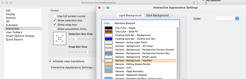
That should be in the VWX Preferences>Interactive Appearances, but I can't find any control for the marquee box. @Anyone know path to change the marquee color? Mine is a light gray border with a light gray transparent fill. You could try changing the Interactive Appearance Setting for General-Background-Top/Plan so that white objects have a difference. I tried wioth a light blue, but it doesn't help very much. Good luck! -B
-
Glad you found it. I said "Layer" pull down. I meant the Active Plane pull down. -B
-
Do what Pat sez. It gives points only on the contours, as you requested. Probably lots of them. If the selected spacing misses some sharper contourq curves, add a few extra loci by hand. A similar approach is to create, in a new class or layer, an array, over entire site, of 3d Loci on layer plane, via the Edit>duplicate array command. Choose xy spacing values to optimize the count. Send to surface. Call the xyz values into a worksheet and export csv. None may land exactly on the contours, but will be evenly distributed over the site. If that’s any advantage. -B