Benson Shaw
-
Posts
4,316 -
Joined
-
Last visited
Content Type
Profiles
Forums
Events
Articles
Marionette
Store
Everything posted by Benson Shaw
-
Line bridging tool, how does one eliminate the gaps?
Benson Shaw replied to LarryO's question in Troubleshooting
Some thoughts about this: General - 1. The tool is completely undocumented - No topics in HELP. No cursor or tool hints. No descriptions in the tool prefs palette. 2. Engage the tool and draw a Bridge Line. Defaults to Cover Weight 30. Ungroup it to see the 3 components: An 180° arc with line weight controlled by the Attributes Palette - this is the visible bridge . . . in front of . . . A 160°arc with line weight 150, and pen color same as vectorworks background color - this "blanks out" the crossing at the line/object being bridged. A diameter line across the arc with line weight 30, color same as vwx background - This covers the bit of leader/source line under the bridge. 3. If Manual Cover pref is enabled, the two "cover" objects' line weights adjust proportionally, with the straight segment adopting the Manual value. The Gaps - 4. Due to Vectorworks rounded line ends, the background diameter line covers a bit of area past its ends and outside the arc, causing those "gaps" on either side of the bridge object. If the Manual setting is large, even the rounded ends of the background arc could cause some of the gap area. 5. The gaps will be accentuated by the vwx Zoom Line Thickness pref - toggle it to explore. Possible bug - 6. In my tests, the "Pick Up Class" works in design layers, but not in the SLVP Annotation space (eg other leader lines). Working in the Annotation space, the Bridge Line object always acquires the active class attribute. Or, maybe I'm missing something. -B -
Help with georeferenced point file importing where it should be
Benson Shaw replied to PNWPaul's topic in General Discussion
OK, Glad this is being addressed by @Vlado and others. The LIDAR surveys and subsequent contour shapefiles, point cloud LAS/LAZ files and xyz data files for this region of the USA are collected and created by the Pacific Northwest Lidar Consortium. These files are hosted and available for download at the NOAA Data Viewer Portal website: https://coast.noaa.gov/dataviewer Perhaps some of the info below about the PNLC data could help sort this. And I present a workaround. PNLC "About" page: http://pugetsoundlidar.ess.washington.edu/About_PSLC.htm PNLC Tech Spec document - collection and data processing info (Projection, etc): http://pugetsoundlidar.ess.washington.edu/Technical_Specifications_withAppendices.pdf LAZ files from https://coast.noaa.gov/dataviewer imported into vwx2023 Same files, either new download or reused from local OS folders refuse to import into my vwx2024 - Corrupt data notice. Try with the attached zips of folders from NOAA. One is .shp with contours (imports fine). The other is LAZ. Here is a workaround for vwx2023: To correctly fit the point cloud data into the Vectorworks drawing: On the NOAA site, determine an Area of Interest and, in a series of requests, use the same capture rectangle (the website preserves it until you log out or redraw it) and receive via email the LAS, LAZ, Contours shp. May as well grab the XYZ, too while you are there: 0. Collect Contour and Point data from NOAA Data Viewer>Elevation. Click the "Return to Viewer" button after each Cart entry to use same Area of Interest outline for each request. https://coast.noaa.gov/dataviewer 1. Import the contour .shp to vwx This set of contours is used as the standard for the point cloud. Contours port in at proper scale and location whether imported to a prior georef vwx, or by letting the .shp determine the georef. Adjust the vwx internal and user origins to suit, and geolocate an image to verify that all is in order. 2. Import the LAZ or LAS. Uncheck the Center on Import option. Point Cloud will locate far from the contours. Group it and move it to, or near the contours via OIP. This makes both visible/selectable on screen. Separate layers is best, Show/Snap Others. 3. The scale will be wrong no matter the layer scale or which import scale. Make a ratio of the x value of the contour and point cloud groups. 4. Rescale the point cloud by the ratio of the groups. Point cloud will jump away to a new location. 5. Move the point cloud group near to the contour group (again). eg zero out the OIP location values of the Point Cloud group. 6. Lock the contour group so it cannot move. In any view except, use the 3d Align command to center the point cloud group on the contour group. 7. Verify that the point cloud is correct scale and location: Superimpose a DTM from the point cloud on a DTM made from the contours. They will be quite close. I made a video a couple in vwx v2023: https://www.dropbox.com/scl/fi/vd7x044kscx1t5l33hmz7/Vectorworks-GIS-2.mov?rlkey=kqejswd63jac1bjutlqjer4zg&dl=0 An alternative control is to use the ASCII XYZ file instead of the contour .shp file. Or, just use the XYZ data to make the DTM. As noted by others, these LAS and LAZ files import correctly to Q and Arc, so wondering if vwx needs an adjust? I think, in general, LAZ and LAZ files port in correctly??? Perhaps these PNLC files are uniquely problematic for vwx? Attached find a .shp and a .laz (GeoID 18) collected today and describing an area in the northwest Seattle, WA, USA. Contours import as expected. LAZ does not import into vwx2024. (My 2023 is expired, so not able to test) Also tried a LAZ in GeoID09. Did not import. -B wa2016_pslc_king_Job978312.zip wa2016_pslc_king_Job978313.zip -
Good idea, but no. My smart options: Basic Palette, Enabled Tool options, 3d Tools Palette, Standard views. -B
-
This may be unrelated . . . M1 MBP. Onboard screen only. MacOS 13.6 Ventura. VWX 2024 3.1 During a recent work session, my cursor cues and snaps were working as expected, then suddenly snaps stopped working. I tried a few things short of relaunch/reboot: move/zoom, group/ungroup, create new objects, toggle layer view, toggle tilde key, more. Turns out the Object Snap somehow became disabled. I do not believe I moused onto the menu bar snap area. Is there a key combo for snaps? I may have used the tilde key, but in this case it was not stuck. Clicked the Object Snaps icon to enable, and all snaps worked as expected. In a subsequent work session, the tilde key DID stick, causing the snaps off until I tested the key. -B
-
Stupid workaround (tip o’ the hat to islandmon). Model a base unit symbol containing a short length of profile extrude pierced by a single slot. For any specific length, DAP or MBP. Add Solids. One or both ends may need ungroup and Split to create a fraction of the base unit. Or just dupe enough to create a full “stick”, convert that to Generic Solid. Save to resource library as converts-to-group symbol. Split as needed after insertion. -B
-
@InchSw3 Welcome to the forum! Trouble shooting is easier if you add a signature to your post showing vwx version and some basics about your hardware: Click your name at upper right of the Forum window, choose Account Settings>Signature. Several things to consider about 2d color areas in Viewports: Your VP screenshot shows a red border which means needs to update. Select the VP>Object info Palette (OIP)>Click the Update button. Button shows red text when VP is out of date. Do an Update after every change to VP parameters to implement the parameter change. VP OIP has option checkbox to Display Planar Objects, about middle of the VP OIP. Check the box and update the VP. Your 2d colors should appear. Sheet layer has a default render dpi of 72, which is fast for tests, but too jaggy for presentation. Edit the Sheet Layer to increase the dpi when the VP shows desired colors and other effects. 300, 600, or even 1200 might be needed, but can cause slow render. VP Render modes, near bottom of OIP: Test your VP changes in the Shaded mode, it's usually fastest. In the Design layer, each "Carpet" could be exported as an image, and then image used to create a full scale texture, and the texture applied to a blank 3d shape corresponding to the particular carpet. This would show the colors in 3d views, (incl Top), but not in Top/Plan. or Each areas of same color, eg all the brown shapes, within one carpet could be extruded as a single command, to a shallow or zero height. Do this for each color in a carpet, then Group the extrudes for that carpet. This approach also shows color only in 3d views, but not in Top/Plan. #2 seems best bet. #5&6 are lots of work and probably not worth it for this, but something to explore as you learn Vectorworks. Post back as needed. Others may have other approaches. -B
- 1 reply
-
- 1
-

-
Long shot, similar to georef idea, but Maybe the source file of the mislocated objects is the problem? Rather than the target file? Here is one scenario : If the source file Unified View>Ignore layers of different scale is disabled, or if the Unified View is disabled, a view of several layers could show apparently properly located objects, even with one layer at different scale. But it would be a deception, and difficult to achieve! The different layer would be zoomed and panned, and objects arranged so that the contained objects appear proper size and location relative each other, AND to objects in the other layers. This would be a fragile arrangement - ANY change to view (pan/zoom/3d view) in any of the layers would destroy the deception. Anyway, Paste in Place from that off scale layer would produce your anomaly if layers in target file are all same scale and Unified View is enabled. Whew! Reminds me of a painter I met who was attempting to paint various shades of “white” on the various planes of his sagging plaster/lath kitchen ceiling. Goal was to have it appear a uniform color at night when the center, twin bulb incandescent fixture was only light source in the room. Wasn’t going well. -B
-
Installed Cityblueprint Font But Still Shows Up as Arial
Benson Shaw replied to Lance C's question in Troubleshooting
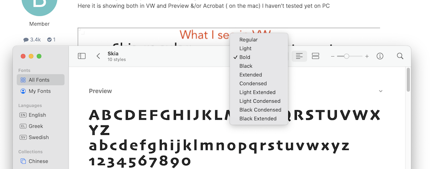
@bcd Found same results by placing the text objects on a sheet layer, then Export or Print or Publish the sheet layer page to desktop. I placed screenshots of the pdf text areas onto the vwx sheet layer. Same result with drop & crop the pdf text areas onto sheet layer. MacOS print to pdf shows the bolds. Export or Publish (with or without subsets) from vwx misses the bold. Screenshot of Skia in FontBook shows extensive suitcase of bolds, condensed, etc, so bolds should not be OS inventions. -B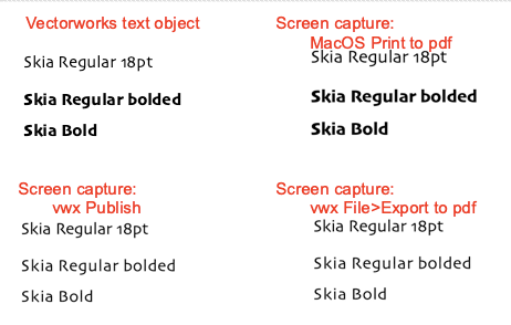
-
Apple macOS 14 Sonoma Compatibility - Feedback
Benson Shaw replied to JuanP's topic in News You Need
No posts in a while. Finally thinking of upgrade from MacOS Ventura to MacOS 14.3.1 Sonoma. Are we fully compatible now for vwx2024? Thanks -B -
Seeking advice on creating massing model of complex roof form
Benson Shaw replied to Sidney Rofe's topic in Architecture
I guess it depends on where the level line is (roof face axis). I put it on the gutter line. -B RoofPuzzleVideo(1).mov -
@bob cleaver TOTALLY not short shrift, and you are totally welcome. The forum’s a pleasure. I’m learning all the time and giving back when possible. Now, if we could just get this command added to the fix list . . . -B
-
Function definitely does not work! If Pad from Grade Limits worked as designed it would: 1. Create uniform grading at designated slope from pad to grade limits. 2. Create a level pad shaped by intersection with slope faces. 3. Place that pad at elevation of balanced cut/fill. It accomplishes 1 and 2, but completely misses 3. Hence the workaround. Workaround is time consuming! True, but other methods to accomplish 1,2,3 would also be time consuming. If working at mm precision for pad elevation, I think fewer than 10 attempts should resolve it . . . Workaround is imprecise. mmmm I think it is as precise as patience allows. Seems the slopes are correct as long as the value is keyed in at each attempt. The pad elevation and therefore Cut/fill balance are limited by construction precision, rather than vwx decimal precision. A millimeter deeper cut or 1deg steeper slope might flip the fill from import to export. Balance point is somewhere between at about 8 decimal points. Remove from program? Interesting idea. Or maybe disable it but show grayed out text in the menu with a “We’re working on it” notice? Add a date stamp or count down so we see interval to the fix. Also, just curious, @ landscape architects, is this a must have feature? use it on every project? Is there a common method without the command? Did it work in some distant, earlier versions? I have not seen earlier discussions here. -B
-
@aage.langedrag, @Katarina Ollikainen, et al. Problems with the Create Planar Pad from Grade Limits are discussed in this previous thread: https://forum.vectorworks.net/index.php?/topic/111998-creating-a-planar-pad-from-grade-limits-but-planar-pads-without-elevation/ But it went to wider issues, so starting new here. The big fail is that the command creates a pad at seemingly random elevation, instead of at a z value that would balance the cut/fill inside the Grade Limits. OK, I even suggested moving the DTM up/down to the pad elevation and recreate pads repeatedly to find balanced cut/fill then move entire assembly back to original z. Sorta works but fraught. I find now that a different command controls the pad elevation in the Pad from Grade Limits: Create Objects from Shapes > Site Modifier > Pad > set the elevation. Delete that new pad. Create Pad from Grade Limits will now match that elevation. Perhaps others have discovered this already, but offering here for the brain trust to pick at. Might help with fixing the bug. Video and file attached. Note: Pad via Objects from Shapes defaults to elevation 0, which explains why many tests of the Pad from Grade Limits creates a pad at z = 0. -B Pad from Grade Limits(2).mov Pad from Grade.vwx
-
Bump Does anyone know what is reported by the volume calcs of a Pad inside a Grade Limits? -B
-
@MGuilfoile That file name looks strange - like it's a repeat paste? Is Loft File 02.vwxLoft File 02.vwx correct file name? The forum definitely accepts vwx files, pretty much any version and from any OS. A file used to be refused if over a size threshold, but haven't seen any limit lately. Try again if you have the patience - drag/drop the file (the icon of the file) into that area for attachments just below the text area of each post. -B
-
Maybe a ripple somewhere in the surface? Shelling greater than 4 inches creates a self intersecting volume, causing calculation fail? Sometimes a workaround is to shell to a value that DOES work, then, while the shell is selected, adjust the value in OIP (as opposed to starting a new shell at a higher value). 4 to 40 seems a stretch, but might work. Post a file! -B
-
ASSOCIATE CERTIFICATIONS Exam question 17
Benson Shaw replied to JzWiley's topic in General Discussion
Aaargh! My opinion based rant: This concept trivializes the powerful and multi use Class and Layer components of Vectorworks. I suspect this is some legacy of early days in Vectorworks to help those transitioning from other software, confronting for first time ever “something” beyond class. Anyway, it is an assertion, merely rhetoric with some truth or usefulness to it, but very limited in outlook. I think as training and core concept knowledge it is at best a tip for someone struggling. It is not even close to worthy of Core Concept mastery status nor inclusion it the cert tests. Individual designers and offices will adapt the Vectorworks Layer and Class system to meet their individual workflows and efficiencies, which may be quite successful even though different from the expected dogma. Layers and Classes are two of several amazing sorting mechanisms in Vectorworks. One could also include Data Vis, Saved Views, Referenced files, Resource Manager items, various Styles, and more. All can be used in combination to sort, isolate, organize or otherwise aid in design, presentation, build, maintenance, archiving of our work. Layers and Classes are remarkable, flexible, and not at all limited to What or Where! One can use layers OR classes to sort for What, Where, When (Project phases? Design iterations?). Some would even include How (CNC paths?) or Who/Why (Specs? Notes?). And, about another question based on an assertion, with a dogmatic answer: Which is the MOST IMPORTANT palette? *(Spoiler Alert, can you guess? - the test writers and curators want answer spelled backwards below) My answer - The Palette I am currently working with. All the others are non important at this moment. OK. End of Rant. Knock me down if you like. -B *(PIO) -
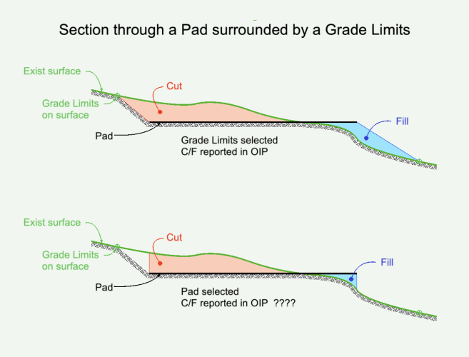
Site model. Single Grade Limits. Single Planar Pad inside the Grade Limits. Elevation of Pad causes both Cut and Fill. Cut/Fill values in OIP are same if Site Model is selected or if Grade Limits is selected. This makes sense. Cut/Fill values if Pad selected are not same as SM or GL values. What volumes are reported if Pad is selected? -B
-
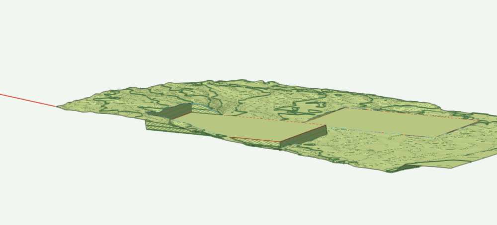
Regarding original topic about the Pad from Grade Limits: I call this the Move the Mountain to Mohamed Workaround. Problem - Planar Pad from Grade Limits command places pad at z=0 instead of at z=Value where desired slope produces cut/fill balance. Solution - Move the DTM and all extant site mods down (usually) by that z Value, run the command, make adjustments to balance the cut/fill, return DTM and all its modifiers up to original z. Needed: 3d Marker at an Anchor point, eg one end of a 3d Poly at one corner of the DTM. Estimate of distance to move the DTM down. Midway between Grade Limits (GL) high and low points. This was only OK. Better estimate uses Center of Mass of the patch of terrain mesh enclosed by the GL. To find this, duplicate the DTM to a blank layer. Crop it to outline of the GL, Ungroup. Delete components except the mesh. Apply Model>Volumetric properties. Note the Center of Mass z value. This is the estimate. Delete the little patch of mesh. Value of desired slope. Process: Place the Marker at Anchor point. Move the DTM (and Site Mods) straight down by estimate value. Use Move 3d for this. Select the GL and run the command. Update the DTM. Update the Cut/Fill calculation. Note the cut/fill values. Close enough? Select and move everything back up to the anchor point via Move By Points. Update again. Not close? A choice: 1. Adjust the pad up or down, eg 1mm increments. Update each time. Repeat until balance achieved. This also changes the slope (maybe unnoticeable), but easy because DTM and Calc updates both available in Pad OIP. 2. Delete the Pad. Adjust the DTM up/down in increments. Update DTM. Select the GL. Run the command. Update DTM and Calcs. Repeat as needed. Slope refreshes to desired value each time. Move the assembly up to Anchor Point via Move by Points. Repeat this process for each Grade Limits on the DTM. Might be a good idea to move completed Pads to a storage layer that does NOT affect the DTM, so they do not confuse current work. Return all Pads (or Duplicates) to effective layer when all are adjusted and the DTM is at the original Anchor position. Update the DTM. -B
-
@line-weight Thanks for comments! I was just experimenting with the geometry and found one way. Rise/run vs angle is about same effort, but extruding the perpendicular DOES provide both rise and run from OIP, which can be convenient. "Facia", sorry, I should have said abutting face. That was my point, anyway. I didn't take it as far as the construction detail. As you say, the mitre join is way to go. Roof joinery has such interesting challenges, design as well as build. -B
-
Glad for your successes. Temporary isolation you describe is a great strategy. Make Saved Views for repeated visits to those limited layer/class sets. To easily return to "normal" view, keep a Saved View with ALL the normal visibilities. Grouping objects for work, then ungrouping is another quick isolation. Use the Menu bar buttons switch between Layer Plane and Working Plane contexts. The tilda key temporarily disables snaps. Esc key clears the acquired snaps. Holding the space bar temporarily activates the Pan function by default. But while you hold the space bar, you can also enable and use any other tool - click in the tool palette. This is helpful if you have a snap acquired, but need a different tool. -B
-
@girwin Would this help with roof face tilting? -B
-
Some recent posts about roof face with cross slope made me curious. It is a geometry problem. Here is one solution in a simple rectangular context. Process starts at a control edge with known High/Low points - edge of adjoining shed roof, top of a sloped wall, etc, plus the proposed high point. Things needed for parameters of the Roof Face command, all determined via vwx geometry: 1. Locate the roof face axis = a level line across the imagined new roof face at height of the control edge. (h=4 in example). Analysis tool helps this. 2. Locate the the line perpendicular to axis from control edge low point, and . . . 3. Find the angle along that line from control edge low point up to the axis height. Video note - A 3d poly was created to represent plane of the new roof and find the axis. 3d poly is a perimeter. Analysis tool needs surfaces. 3d Poly was converted to Mesh. NURBS surface would also work. Analysis tool happy. Wish/Enhancement - Roof Face command adds a 3d 3 point mode, sort of a hinge: Select the roof face footprint. Click the control edge low. Click the control edge high. Click the roof face high point. The command runs. The current modes, including 2nd Click Height, all employ axis parallel to ground plane (or maybe working plane - too confusing!). -B Dbl Tilt Roof(1).mov
-
If roof style datum is Top shouldn’t the option place top of roof face at the height? Sorry, can’t test for myself at the moment. Will try to look into it later. -B
-
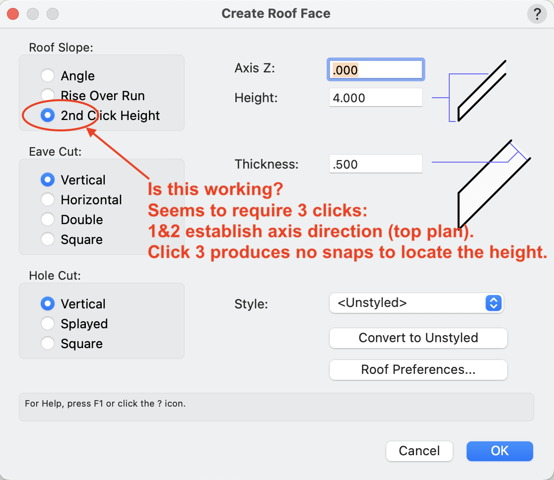
Trying to make roof face via the pref labeled "2nd Click Height". Here is Help text: 2nd Click Height Creates a roof slope based on a mouse click position (this option only available in Top/Plan view). Enter the Height for the second mouse click. Working in Top Plan, with normal snap options. 1. Number of clicks and what they accomplish: I think(?) this process actually requires 3 clicks. Is this incorrect in both the dialog and the Help? Clicks 1 and 2 establish the axis for the slope, similar to the other modes. A 3rd click is required to complete the command, same as other modes. 2. Snaps gone Snaps work as expected for Clicks 1 & 2 No shaps available for 3rd click. No acquisition of points, edges or edge extensions. Tabbing into smart cursor allows entry of the L field, but that produces roof face with incorrect height. -B RoofFace(1).mov