Benson Shaw
-
Posts
4,315 -
Joined
-
Last visited
Content Type
Profiles
Forums
Events
Articles
Marionette
Store
Everything posted by Benson Shaw
-
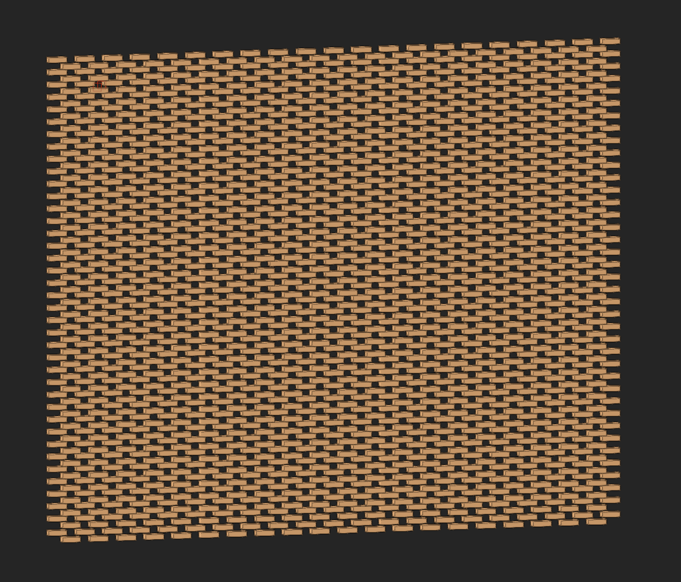
Probably a texture would do the trick. But if you want to model it, I suggest make a brick symbol (2 or 3 of them with varying color). Duplicate Along Path (or Move By Points) horizontally for the 1st course. Fixed distance to accommodate the blank spaces. Make a symbol of this. Then dupe the 1st course symbol and modify for the next course up with end offsets. Then dupe the two symbol courses vertically via Move by Points to complete the facade. If needed, after the whole facade is formed, ungroup a few courses and replace a few brick with the alternate colored symbols. Pain, I know but goes fast once you get the hang of it. Hopefully others will have better ideas. -B

-
Fillet a polyline doesn't cooperate
Benson Shaw replied to MartinBlomberg's question in Troubleshooting
The container/perimeter object OIP can show Closed even when the internal polys are not closed. Apply that Cmd[ shortcut to access/edit the internals. -B -
Fillet a polyline doesn't cooperate
Benson Shaw replied to MartinBlomberg's question in Troubleshooting
The fillet tool has a VERY small value (13) in this file. It is filleting, but not discernible except at huge zoom where the graphics are, um, confusing. And, one of the internal polylines is not closed. That open corner does not fillet, until closed. HTH -B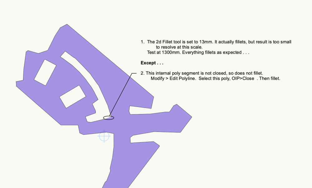
-
Cutting Complex Patterns Into Solids
Benson Shaw replied to Chame_liam's topic in General Discussion
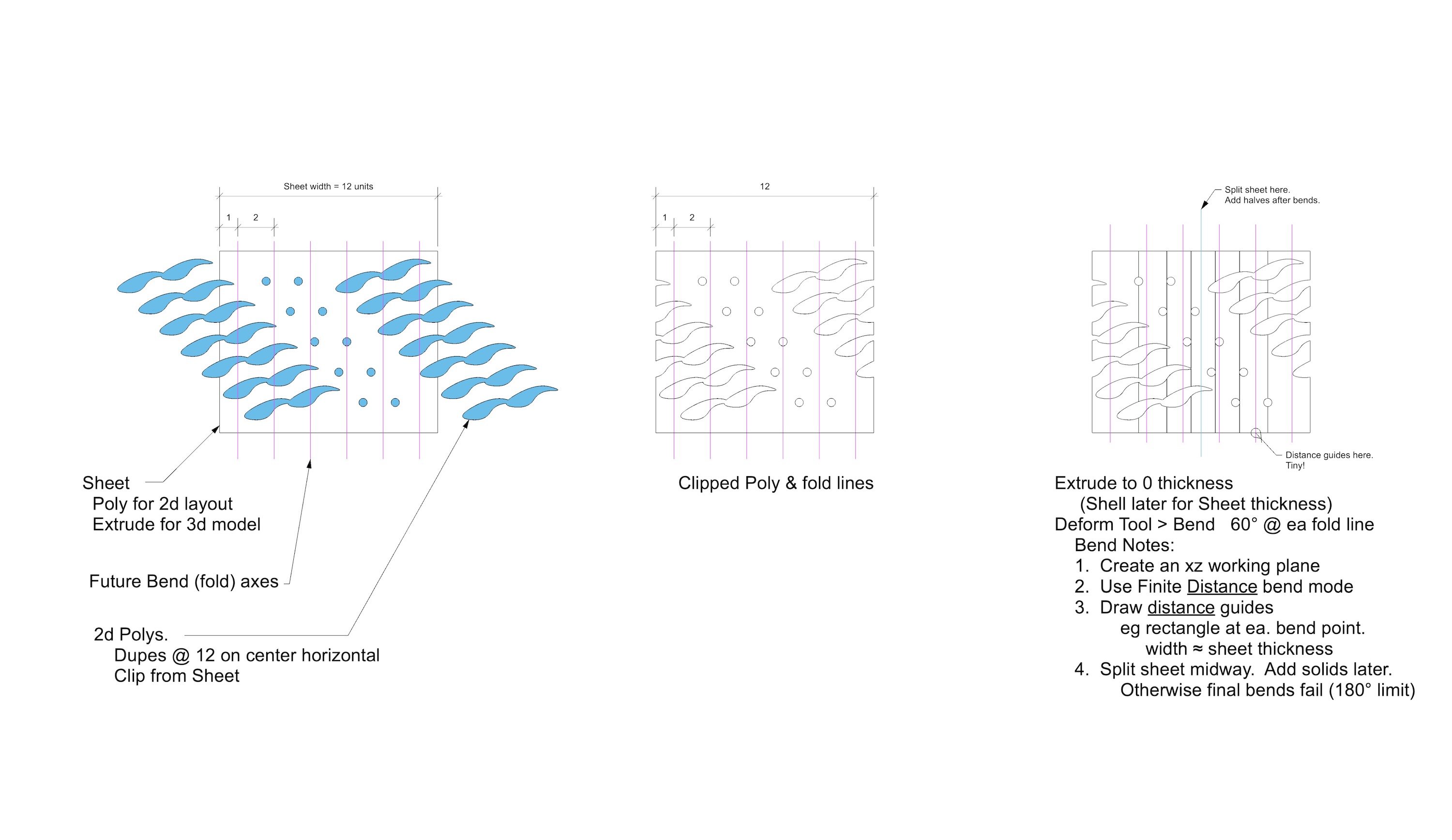
Forgot to mention some potential cutting issues. Check with the cutting personnel for tips and limitations: The 2D layout is best if the drops are individual polys arranged on the sheet outline - whether whole sheet or the 6 facets. Rather than the clipped poly used for the extrude. Some cutters software interprets only straight segments and circular arcs. Beziers or splines may not be recognized or may be “exploded” into a few or many straight segments. Get a proof prior to the cut. -B -
Cutting Complex Patterns Into Solids
Benson Shaw replied to Chame_liam's topic in General Discussion
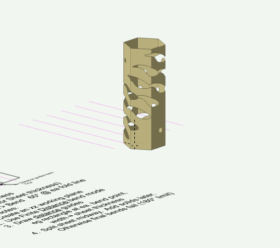
This doesn't discount any of the previous ideas or methods. All good. My experience is that laser cutting would be full sheet with subsequent bend to 3d. Cut/weld facets would likely be much more expensive than cut/bend a full sheet. The 2d on full sheet is not so difficult if the drops (cutout shapes) are arranged/placed to match when the edges are joined. Sheet width is 6x facet width. The drops need to be placed at integer multiples of the sheet width (or certain fractions thereof). Sheet metal bends are always slightly radiused. Your sheet metal shop can help determine if that level of accuracy is required. So self direct whether to undertake this technique via Deform tool to model similar to final product. Another note: In my model, the extrude has zero thickness and then is shelled to sheet thickness after bending. The bend can be made with a thick extrude, but vwx takes successively longer time to process each bend command. There is also some mystery limit to the sheet/shell thickness. ??? Anyway, here's the skinny -B HexColumn(1).mov
-
Duplicated contour line labels are a problem
Benson Shaw replied to Jeff Prince's topic in Site Design
Doh! Now I have to test AGAIN! Thought I made this work, once upon a time. -
Duplicated contour line labels are a problem
Benson Shaw replied to Jeff Prince's topic in Site Design
@Minna I think the workaround requires several things: A. Place all your site modifiers on layer(s) separate from the DTM. B. Make a copy of the existing DTM data C. Create a new DTM from this data on a new, blank Design Layer. Lastly, use the DTM settings to apply all the site mods layers to the new DTM, and update the new DTM. If terrain and contour labels are as expected, delete the original DTM (or, better, the orig DTM layer assuming no other objects present on that layer). Any further site mod edits or addition of new site mods will likely create duplicate contour labels. If so, repeat above. hope this works for you. -B -
Couple of side bar questions: 1. Some folks seem to submit bugs and somehow find, or receive an ID for it (eg VB#xxxxx), and apparently know some URL or other way to follow progress related to the submittal, or work on the bug. How does one get into that loop? 2. I also see forum threads referring to submittal of a JIRA. What is a JIRA and it's purpose? Thanks -B
-
Non-existent lines appearing on sheet layer viewports
Benson Shaw replied to oliver.williams's question in Troubleshooting
This time I did file a bug report via the webform. So, I guess? it will?, maybe?, be looked into ??? meanwhile, I also played a bit more with my file and the troubled objects therein. These were extrudes of polylines. The polys have lots of holes clipped out. The clipped poly was drawn and extruded on layer plane, then rotated 3d to xz plane for rendering. One new test - If I copy/paste the source poly onto the layer plane, and extrude it, and leave it on layer plane, it renders HL with fewer anomalies than the same object rotated 3d onto the xz plane. Further - an Extracted face of the extrude (a NURBS Surface on the xz plane) renders HL with only minor anomalies, but a Shell of that NURBS Surface renders HL with a bunch of anomalies. -B -
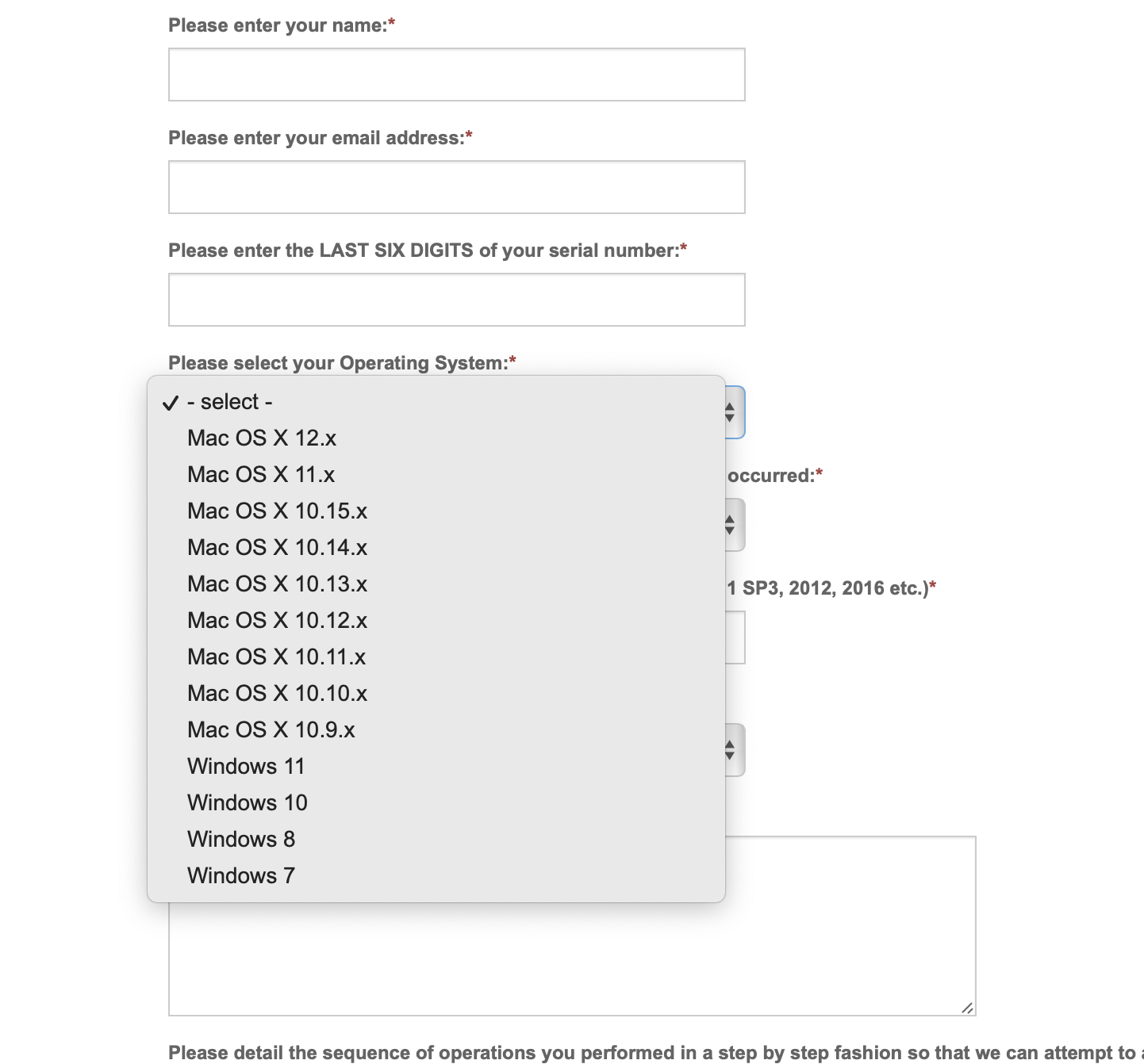
The online bug submit form has a pulldown to choose an operating system related to the bug submit. The MacOS choices top out at 12.x The current Mac version is 13.x (Ventura). 14.x (Sonoma) is coming soon. Is this bug form abandoned? Should we submit bug reports elsewhere? How would one know whether a submittal was received? -B

-
Non-existent lines appearing on sheet layer viewports
Benson Shaw replied to oliver.williams's question in Troubleshooting
Those tests with the decorative wrought iron produced unwanted or out of place HL lines in both Design Layer and Sheet Layer Viewports. I don't recall whether I filed a bug. Will file one. -B -
Convert objects made of 3D polygons to solids?
Benson Shaw replied to Christiaan's topic in General Discussion
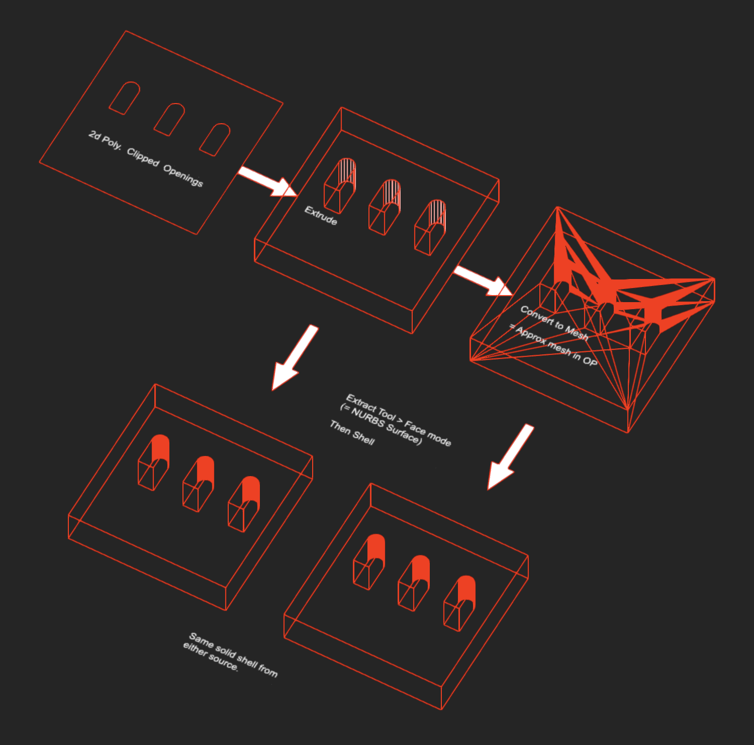
I think Extract, then Shell should be best method. My initial thought was that the trace would produce a more viable or vertex efficient source object. Not borne out by testing. I think the Extract (face mode), then Shell should work really well. I tried to approximate the obj mesh by drawing a 2d poly, clipping the openings, Extrude, then Convert to Mesh (produces a more complex mesh than the OP, but similar). Tested the Extract/Shell process on both the extrude and the mesh. Same result either way. The intermediate Extrude is a good solid, but probably not worth the effort to trace, or to extract edges. -B
-
Convert objects made of 3D polygons to solids?
Benson Shaw replied to Christiaan's topic in General Discussion
@Mauro Pujia post the .obj. and/or the vwx file. We can propose some actual solutions. Meanwhile, if only this object, It might be worth the effort to trace the front face with 2d shapes, clip out the openings and extrude. - B -
@jmcewen hope it’s working for you now. Guide objects can also help. 3d loci, corner of extrude, even xy plane objects, etc are very helpful plotting xyz curve vertices. Post a screenshot or, better a file to show your context. Specific advice will ensue. -B
-
I don’t think vwx NURBS can be modified that way. An alternative is to place a bunch of 3d loci on the existing curve and generate a new NURBS curve (interpolated points mode) by snapping sequentially to the loci. Initial loci placement can be individuals, ornvia DAP , plus any special locations desired. Admittedly, this new curve will deviate from the original, probably not by much. Sometimes, increasing Degree in the OIP, or the Rebuild NURBS in the 3d power pack can be helpful. -B
-
I think there is a vwx pref for this. Away from keyboard now, but remembering in early (?) versions, didn’t the full screen cursor cause this loci behavior? Also there is a pref for show hide 3d Loci. display tab, or session. Try toggling those prefs. -B
-
Many others have claimed this in the past. I think working with meshes is not always stressed in training or self learning. Reshape tool is the “go to”, but does not produce the desired result. Gotta marquee vertices with the Select tool. For thickness I would shell individual faces. Or one could shell for the face material then create a working plane and draw & extrude polys representing the lumber elements. Then model the hinges and bent nail connectors, etc. As @line-weight points out this would best be driven by intended construction and materials. Flats joined by hinges are common, some with face material on both sides. Visible joints can have a fabric cover. All depends on scene change, crew skill, etc. Others with more experience may critique all that and jump in with techniques for viewports with dimensioned shop schedule. -B
-
Meshes work just fine -B Mesh(1).mov
-
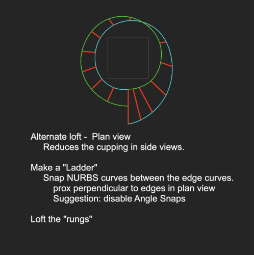
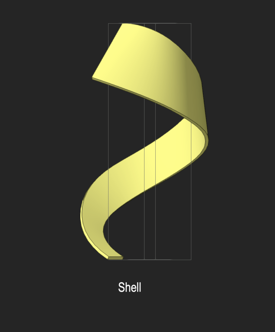
@VIRTUALENVIRONS Cupping is more of a carpentry/woodworking term. The effect of the surface of a board raised at the edges or if you flip it over, the center is raised. Wood/lumber often cups after it gets wet, or even from uneven drying between milling and sales point. My original loft between the two edges suffered from this. See it in the side view of my loft and shell. In my tests, no amount of "matched" point edge redux (thanks again for that tip!), degree adjustment, extending shorter one (cut back the loft after), etc pulled the cup to flat. -B
-
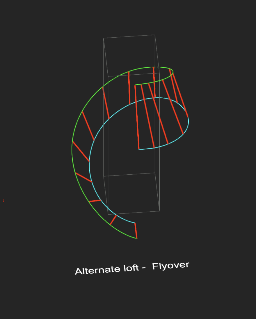
Still thinking about this. My example above is cupped/bowed between the edge NURBS curves. Here is an alternate version to prevent the cupping. @VIRTUALENVIRONS That Dupe Along Path is useful for loft setup in many situations, but here, the edges cross (in plan). I guess one could sequentially rotate the dupes. -B
-
Simple solution to fill in empty space?
Benson Shaw replied to Michael Gillis's topic in Solids Modeling
Oops, mashed up two versions of this. Should read thusly: . . . Creates a group containing the 8 NURBS curves - looks like a rectangle and a curved rectangle. Edit the Group, Select All, then Compose. This "joins" them into two NURBS curves (the flat rectangle and the curved rectangle). Extract the back edges of the curved piece and Compose same way. Select both . . . Loft can be done in the Group, or Ungroup, then Loft. -B -
@VIRTUALENVIRONS Thanks for these! Very generous. Good variety. With some of the standard stone textures they look pretty good - need to fiddle the texture scale. I found for even more variety and surface modulation I can stretch/compress the individuals, or bash a couple together, then Add Solids, or Solid Subtract, and Convert result to Mesh. -B
-
@Tony W if you want an enclosed area or volume in Vectorworks, draw it as such. Adjust line weight as needed. Alternately, if an existing line (or curve) needs conversion to an enclosed area . . . The Offset tool with option to “Close open curves” does what is described in original post. Tool pref provides parameter for offset distance. Possible problem: the offset tool offsets to one side or other of source object, but does not offset centered on the source. Workaround: Offset twice: 1st time to one side, at half distance, disable the “Close open curves” option. 2nd time offset the new curve to opposite side, full distance, enable the Close option. -B
-
Simple solution to fill in empty space?
Benson Shaw replied to Michael Gillis's topic in Solids Modeling
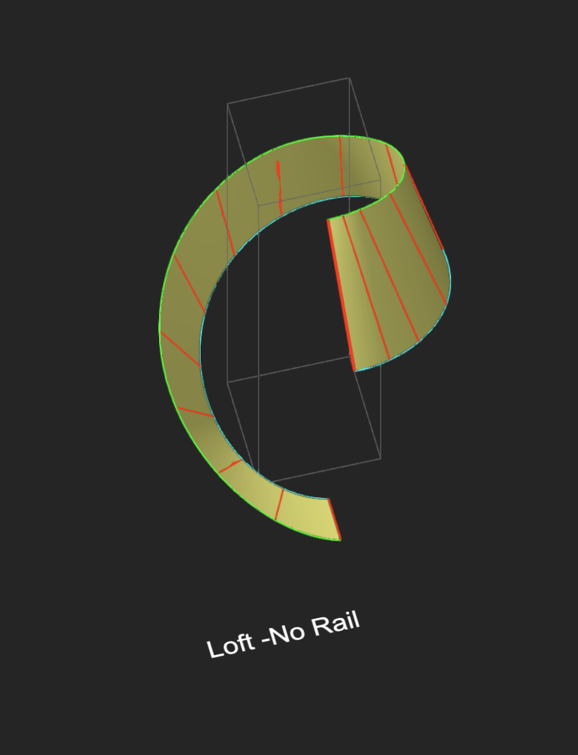
What @jeff prince said, Or, Loft the volume: Use the Extract tool in Edge mode. Extract the forward edges of the flat piece and the back edges of the curved bit. Creates a group containing the 8 NURBS curves - looks like a rectangle and a curved rectangle. Ungroup, then compose. This "joins" them into a single NURBS curve. Extract the back edges of the curved piece and Compose same way. Select both NURBS curves. OIP, Show direction. If not same direction, Select either one and reverse via the OIP Reverse Direction button. When both are same direction, Loft Surface > No rail mode. In the Loft dialog, choose options for Ruled and Create Solid, then click the green checkmark. Result is a volume matching the void that needs filling. Lots of words to describe this, but easy and takes about as much time to complete as reading this. Technique is especially useful when Extrude and PushPull are not viable, eg edges are not planar, faces are not flat, etc. -B -
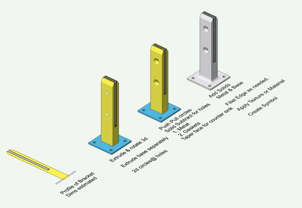
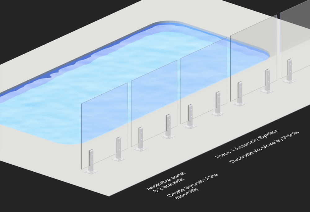
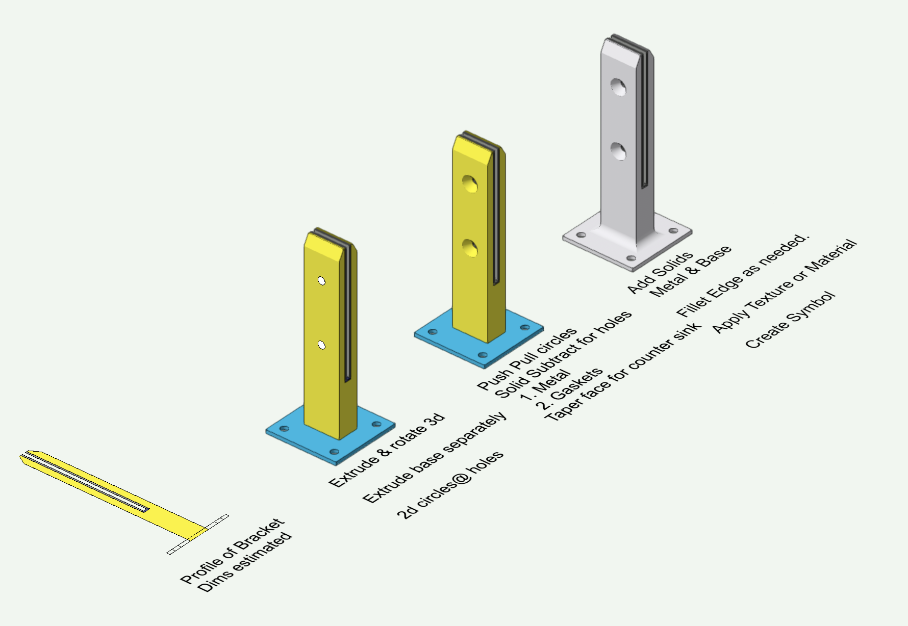
Maybe could do this with fence or other tool, but parameters and hardware might be a pain. Pretty easy to model this. Almost all extrudes unless really detailed hardware. Create a separate symbol for each item (each size of glass panel, deck bracket, hinge, maybe some corner hardware? Assemble the various repeating units into symbols and duplicate them to surround the pool. Attached vwx v2023 has blow by blow on separate layers for the glass panel (just an extrude) and the deck brackets (estimated the dimensions, so a bit out of scale - use a spec if available) -B Glass Pool Wall.vwx