Chame_liam
-
Posts
10 -
Joined
-
Last visited
Recent Profile Visitors
307 profile views


-
We are in search of a Melbourne or Sydney, Australia based draftsperson who'd like to join the team. This is an in person, full time role (we do have flexible arrangements but you'll need to be able to work from one of our offices). Feel free to ask me any questions! https://www.linkedin.com/jobs/view/3896897443/?refId=dDU1Rt4KROyfidkoRg8B9Q%3D%3D&trackingId=dDU1Rt4KROyfidkoRg8B9Q%3D%3D Hi, we are Mandylights! Our team of designers, producers, and technicians delivers end-to-end entertainment architecture for concert touring, special events, light artworks, broadcast, and immersive experiences. We light entire cityscapes and bridges, immerse people in stunning visual environments, take on the world’s largest stadiums and arenas with concert tours, and create one-of-a-kind experiential activations for any entertainment application. We are seeking a motivated individual with a wealth of technical drawing skills to join our busy team. Working and collaborating with the creative and production teams, the Draftsperson works to identify, develop, and execute designs across a wide range of traditional and non-traditional disciplines from concert tours and theatre designs through to light artworks and government or private-sector-led activations/experiential environments. To be considered for this role, you'll need strong knowledge of industry-standard CAD and drawing programs (Vectorworks, Spotlight essential). Additionally, you should have some experience with Depence, R2/R3, and Adobe Creative Cloud. You'll be creative and organised with exceptional verbal and written communication skills and a passion for technical drawing. In return, we'll provide a competitive rate, a role where no two days will be the same, a great team, and exposure to a fun, flexible, and engaging work environment. If this sounds like the role for you, please send your CV and expression of interest to work@mandylights.com
-
Alrighty, talk to me like it's my first day, no suggestion is too basic. I have a number of files that I'm working on at the moment that have ballooned in size quite dramatically, quite quickly. The worst one grew to about 5.5gb in 2 weeks. It's not a huge drama when I'm working by myself as I'm on very quick hardware and have a very quick internet connection in the office but it does get cumbersome when having to share things with others. Over the last couple of years I have gone from just working doing entertainment lighting in Vectorworks (mostly using PIOs) to doing whole production, venue, scenic and site drawings. So my use of tools has gotten wider and I am modelling lots and lots. I know one thing that I'm not doing that will help dramatically is referencing anything that doesn't need to be in the drawing but I'd like to hear about workflows around this when having to consistently be sharing versions of my files with colleagues and external people. One other specific thing that I'm interested in is any modelling tips to keep file size down. I have one particular project at the moment that is requiring more accuracy on the drafting end than anything I have ever worked on. It's an entirely custom build on a super short time line and there's no time for mistakes. So my modelling has been super detailed so I can be as confident of not having fabrication issues as possible. But some of these models are ending up at more than 200mb. One particular one that comes to mind did involve me bringing in some components that came across as .STEP files so I know this isn't helping but again, would love to hear about peoples' workflows for handing these. Thanks!
-
Just a quick workflow question today Does anyone use the ability to class things in sheet layers? Given I'm creating my paperwork here, I've never really understood what the benefit would be in my industry. More so I often find myself searching for things that I swear I've done that I've lost to a hidden class. Or better yet, doing them again only to find the duplicate later. I personally just find it easier to set everything to none
-
This looks stunning but unfortunately not quite what I had to draw. Our model needed to reflect the fact that all of the members of the structure are straight sections so the engineers could sign off
-
Ours is currently seeing a very cold couple of months in Denver
-
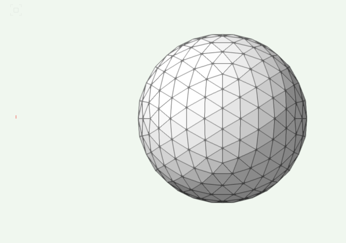
@VIRTUALENVIRONS not quite - difference between mine and yours would be that mine is a 5v geodesic sphere but I'm sure you could have achieved that with your methods. Would love to know how you achieved that in 30 minutes though!
-
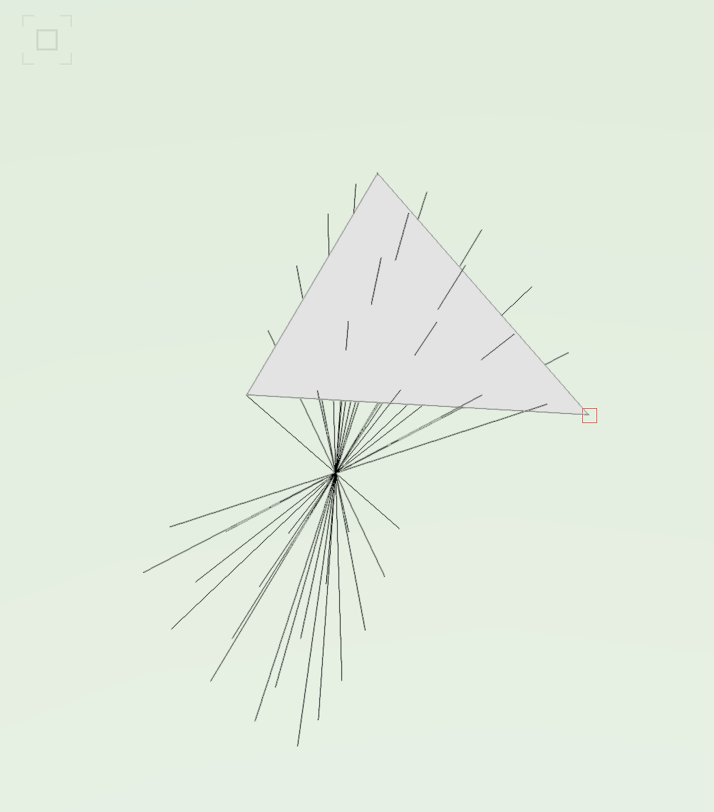
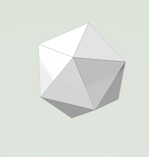
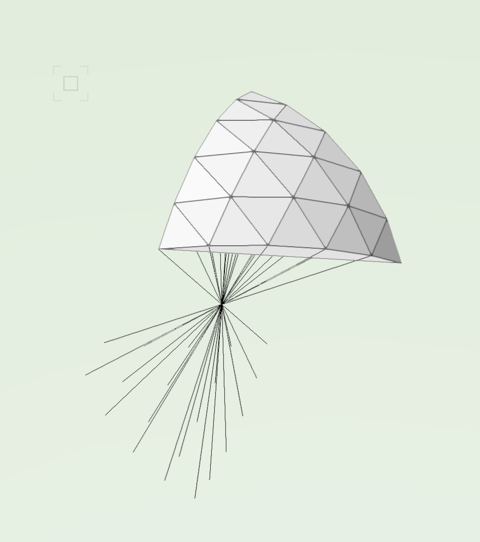
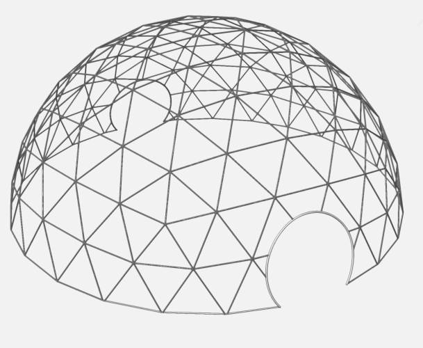
Alrighty - first of all, sorry if I'm using any of the wrong terms here... definitely could have paid more attention in maths in school. So, the company I work for has a custom half sphere structure that we build a light artwork over the top of. About a year back, the structure got stuck in transit and we had to replace our custom half sphere with a geodesic dome for that gig. Now the geodesic dome has made its way into our rotation as they're obviously much easier to procure and ship and today I had to draw the dome as the manufacturer didn't have a CAD for it and we needed to update our documentation. I got there but I feel like it took me so much longer than it should have so would love for any tips or ways to speed up my workflow. Here's what I did: I drew a regular icosahedron using 3 idential golden rectangles intersecting each other and then drew the faces by drawing triangles from 3d polys using the vertices of the rectangles. From there drew lines between the furthest vertices in the icosahedron that all overlapped in the centre of the icosahedron Hid all but one of the triangles and duplicated and rotated the lines so that I had enough points to draw my triangles in. I was drawing a 5v dome Drew triangles in Spent a very long time working out how best to duplicate this set of triangles and rotate them to sit atop the other icosahedron faces (I drew lots of squares and extruded them to set working planes that would be helpful to rotate the set of triangles. I had to do each face individually which ate a lot of time). This is what I ended up with: I then used my internal lines between furthest vertices to help rotate the whole thing so one of the clusters of 5 triangles was at the top From here, I removed the half I didn't need, scaled the dome up to match the size of the real life one, trimmed the bottom of the bottom row of trianlges so that it would sit flat and then had to use extrude along path with a circle for each of triangle (another very slow part, would love any other obvious way I could have done this. And it's also resulted in a lot of unneccessary overlapping geometry). I removed our doors by drawing a cylinder and subtracting solids. Then drew a nurbs curve in between the points of the remaining members and extruded a circle along those paths I definitely learnt some modelling lessons doing this but any other ways anyone would have approached this, I'd love to hear!

-
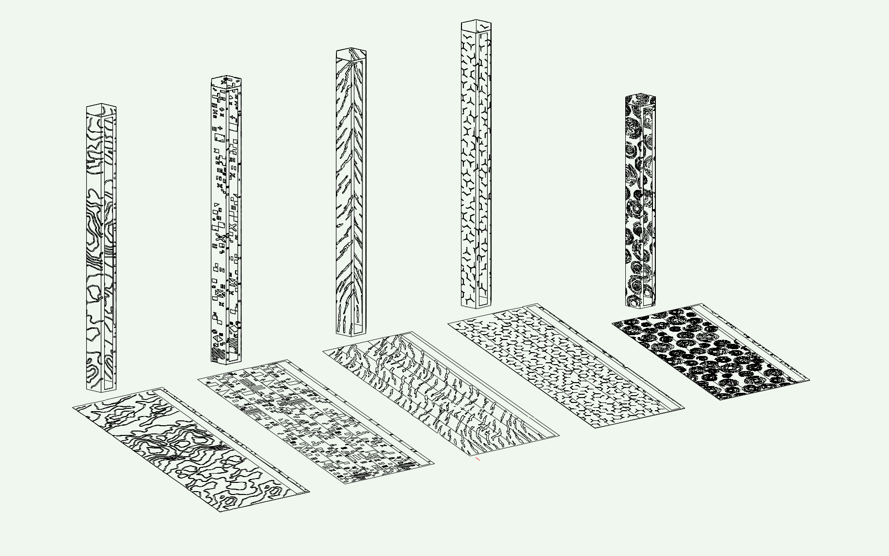
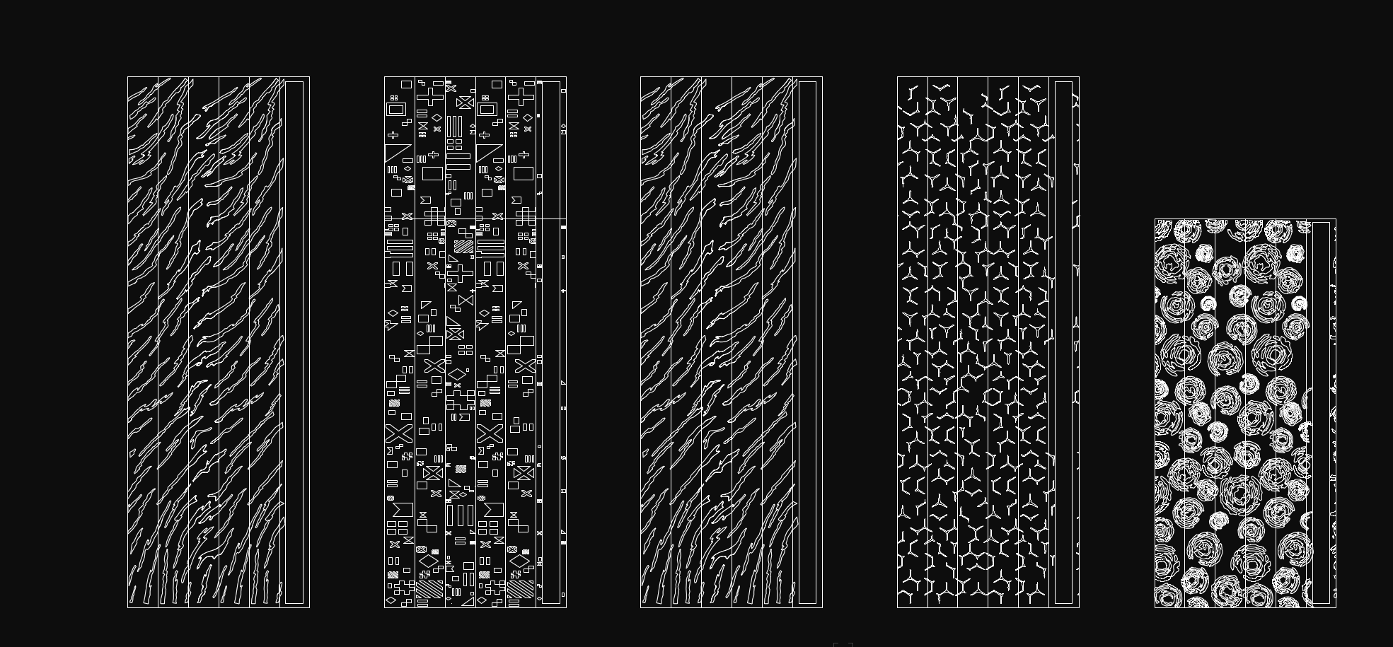
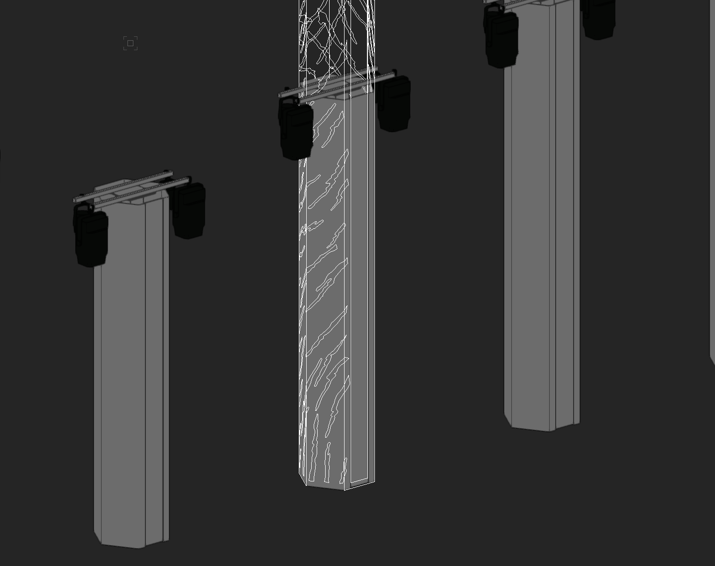
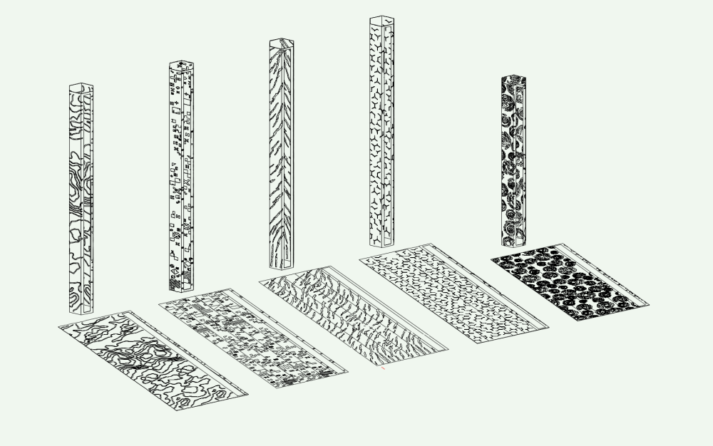
Alrighty! With a combination of most of the suggestions above I got there! Couple of things for anyone playing along... - a couple of the designs I found the easiest way to fix was to jump into Illustrator, use the pathfinder tools on the original paths to cut them out of the plate there, then bring the DWG back to Vectorworks to extrude. This did still require some finessing in Vectorworks but Pillars 1 and 3, 4 were pretty quick using this method. - Pillar 2 I had lots of problems with interestecting geometry but given it is mostly straight lines and 90 degree angles, I spent an hour tracing everything to get it workable - Pillar 5 caused a bit of a meltdown on my end due to the detail so got the original designer to give me those faces as 6 separate nurbs surfaces. Used the push/pull tool on them to extrude. Weirdly I had to use different modes of the push/pull tool for this to work. Some faces worked with the extrude face mode and some only worked with the move face mode. - Other than the last one, I had greatest success working on the plate as a whole design laying flat, then splitting into 6 faces and folding them into a hexagon profile. Thanks all!
-
I've attemped these methods in my initial crack at it... I'm wondering if what I'm trying to achieve is too detailed. Here are the designs I am trying to work with - they'll eventually be laser cut into the plate, acrylic backed and LED behind, hence me actually trying to cut it out rather than just overlaying the shape on the hexagonal pillar. Thanks very much for the detailed answers so far though!

-
Chame_liam joined the community
-
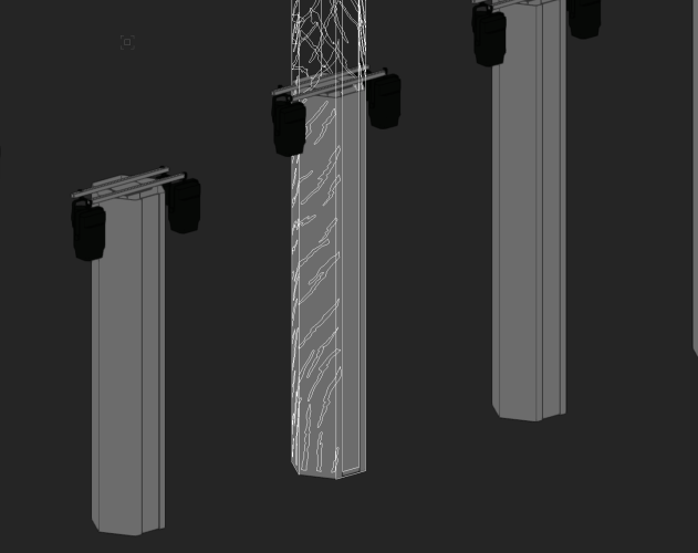
Having a very difficult time with this one and am really running out of things to try. I have a model that I'm working on that has some 4500mm tall hexagonal pillars that are currently just drawn as extrudes. The designer on the project has just handed off to me the DWGs with the patterns we will eventually be cutting into the pillars and we need to get this into our vectorworks model for our construction drawings and then later so I can do renders in depence. From the DWG, everything comes in as it's own polyline which isn't unexpected but is there a way I can do this simply - just selecting the pattern for each one and removing it from the solid? Or removing the pattern from a surface and recreating the hexagonal pillars out of that flat surface? I've tried everything I can think of and it's all either produced unexpected results or has caused Vectorworks to lock up.