


jmcewen
-
Posts
112 -
Joined
-
Last visited
Content Type
Profiles
Forums
Events
Articles
Marionette
Store
Everything posted by jmcewen
-
I opened this tool once assuming it was a tool that allowed you to make parametric chains. It wasn't what I was looking for so I closed it and moved on. But I remembered those curves in the mode bar and assumed the same. Too bad. This sounds like a very powerful tool.
-
Rotate profile around an axis to create a solid ...
jmcewen replied to Etienne_Mallee's topic in Solids Modeling
Both suggestions will do what you want. @Tom W.'s suggestion is the most straightforward once you understand the idiosyncrasies involved. Whatever shape you draw will be swept around its left-most point unless you ad a locus, in which case it will sweep around the locus. In this case, the locus acts as the infinitely small circle you are mentioning. @VIRTUALENVIRONS' suggestion will offer you far more options and will be adaptable to more situations, but will involve a couple extra clicks since you need to generate the rail object as well. I suggest you try both. Figure out which works best for your use-case, but keep the other in your back pocket because you will want to remember it later. -
This would be an ideal use of Chain Extrude, wouldn't it? I have never used it, but it sounds like the primary purpose of that tool to me. Lay out the battens (both seat and back) instead of the frame of the awning that is typically used as an example of how the tool is used. Use a curve for the path object instead of the face of the building the awning attaches to, and use the the rectangular profile of the end of the bench as the profile extruded instead of the awning surface. Again, I never use this tool but if it works the way I understand it, then the whole project should be finished in a few clicks with no deforming involved.
-
Curved vertical would certainly be more precise in terms of maintaining even spacing between rows.
-
Could it be as simple as creating a horizontal plane the cuts through the bowl then finding your curve with analysis?
-
A lot of access for clearing out the ash, and it lets you enjoy the fireplace if you like to sit on the roof staring at stars. These guys knew what they were doing.
-
Non-existent lines appearing on sheet layer viewports
jmcewen replied to oliver.williams's question in Troubleshooting
Just noticed a difference between the "Hidden Line Muddle" example and this example. The other thread is an extrude of a clipped polygon, this is a solid subtraction. Just for larks, what happens if you convert the subtraction to a generic solid? The other thread experimented with converting to nurbs and got modestly better results, perhaps we stopped short, but were on the right path before. I also wonder if minor changes in your geometry such as nudging the depth of one of our subtracted surfaces by .001 might cause a different rendering result. I have had operations fail, then do a solid addition where the added object is entirely inside the other object so it does not change anything visually or dimensionally. After doing this sometimes the operation will succeed. perhaps this will shake something loose in the rendering process as well... I am not suggesting this as a fix-- just as a bandaid if you need this for presentation or something like that. -
Not a Mac solution, but any windows users who land here with the same question can start a recording with window+alt+R. End the recording with the same keystrokes. Video should end up in a folder named Captures in your videos folder.
-
Non-existent lines appearing on sheet layer viewports
jmcewen replied to oliver.williams's question in Troubleshooting
I think you are right, but I have had it in viewports too, especially on pierced surfaces such as clipped poly lines that have been extruded or solid subtractions. Should we expect the behavior be any different between design layer and viewports? -
Yet again... edit VP scale list?
jmcewen replied to DSmith2300's question in Wishlist - Feature and Content Requests
Projects built in US but installed abroad and vice versa or else the project is being sent to bid both foreign and domestic... Just happy dual exists so I don't need to measure twice. -
Non-existent lines appearing on sheet layer viewports
jmcewen replied to oliver.williams's question in Troubleshooting
You aren't the only one seeing it. I have fought it too, to no avail. @Benson Shaw posted this a while back. Baybe he found an answer at some point. -
Yet again... edit VP scale list?
jmcewen replied to DSmith2300's question in Wishlist - Feature and Content Requests
Please be more in depth than just switching between Imperial and Metric! I work 60% of the time in imperial, 10 % in Metric, and 30% in dual. But when working in Imperial only once have i ever needed 1"-100'. I also expect never to need 20x, 50x or 100x. But I do use 1:2 and 1:5 on detail viewports often enough to not want them to go away just because i am using imperial units. Ideally there would be a central menu where we could check the scales we want offered in the pull down. Second would be to right click and pin options to the top of the list, Barring that my third choice would a quick menu of recents or scales already used in the document would be automatically pinned for us to the top of the list like we have for fonts. And I want to be able to save those preferences in a couple templates, so i can have my Imperial, my Metric and my Dual Dimension set and ready to go for different clients. Related-- is there a way to add a commonly used custom scale factor to the list to increase clutter? I have used 1:3 a lot in the past couple weeks and need to make a custom scale each time. Can I add it to the default list somehow? -
I was so happy when I figured that out.
-
Does your keypad have a numlock button?
-
There are worse buttons to accidentally click. I once turned off unified view before I knew much of anything and was totally lost for a whole day!
-
Number Pad / Macro Pad / Stream Deck / Loupedeck
jmcewen replied to Mark Aceto's topic in General Discussion
Redragon M990 gets you up to 23 buttons, 16 arrayed under the thumb, 1 by your index, and 4 behind the scrollwheel, which I think would typically select polling rate, but who really needs that in our industry? Pretty sure they count left right and center as part of the 23 programmable buttons, too. You lose some top buttons on the wireless version of this, so if interested be careful which you look at In my set up with the little brother of this mouse, I use the mouse buttons for views and selection operations, a streamdeck XL on the left for common multikey inputs, and a stream deck pedal for x ray mode. The pedal still has 2 unassigned inputs, and I am trying to figure what is most valuable to put there still.
-
Number Pad / Macro Pad / Stream Deck / Loupedeck
jmcewen replied to Mark Aceto's topic in General Discussion
I lack enough faith in my memory of how I mapped my keys to use one of those without visual remindrs. But if you like that you should check out the Azeron Cyborg. Using it looks like holding hands with a robot.- 72 replies
-
- 1
-

-
- hot keys
- tool modes
- (and 1 more)
-
23 minutes? That is fast! Sure if it is no trouble. I have dabbled in Nurbs to fill gaps in other abilities, but more and more it seems i need to be something i need to embrace as a core competency. I was making my way through the Vectorworks University Core Certification videos while work was slow to try to fill in the gaps in my foundational understanding, but then work exploded in Q3 and i had to abandon it. any thing that will make some of these concepts more concrete will help. the basic tutorial videos often fail to hold attention. Learning from a more complete project may be more engaging. Thank you. @Bill McGarvin sorry for hijacking your thread!
-
Number Pad / Macro Pad / Stream Deck / Loupedeck
jmcewen replied to Mark Aceto's topic in General Discussion
I used my mouse to get around my numpad placement, but I had to remap all the numbers on the mouse to make it match the numpad layout in my mind. Plus i get a few of the single key shortcuts that aren't worth mapping on the streamdeck, but do just fine going under my right thumb. Cheap mouse, works well, pretty long battery life. It is just really big, and that puts some people off. I recently saw a different mouse with 16 thumb buttons, but i don't think I could handle that. UTechSmart Venus and RedDragon Impact Elite are essentially identical. Razer makes the Naga, which seems pretty similar but is 2x the price and you can swap the thumb pad for some different custom key configs as well.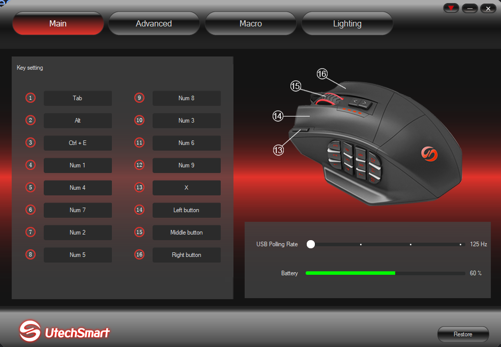
- 72 replies
-
- 2
-
-
- hot keys
- tool modes
- (and 1 more)
-
Number Pad / Macro Pad / Stream Deck / Loupedeck
jmcewen replied to Mark Aceto's topic in General Discussion
Why stop at numpad on the left. How about the whole thing on the left?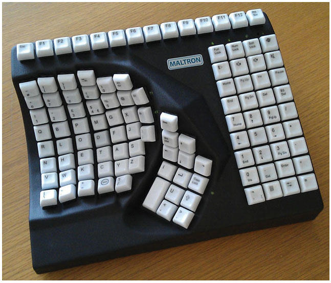
-
Number Pad / Macro Pad / Stream Deck / Loupedeck
jmcewen replied to Mark Aceto's topic in General Discussion
Mapped as console gaming buttons like Playstation maybe? They use circle, triangle square and x don't they? Edit. quick research confirms the use of these symbols on gaming controllers but not necessarily for this keyboard. From an interview with person who designed the playstation controls : Other game companies at the time assigned alphabet letters or colors to the buttons. We wanted something simple to remember, which is why we went with icons or symbols, and I came up with the triangle-circle-X-square combination immediately afterward. I gave each symbol a meaning and a color. The triangle refers to viewpoint; I had it represent one's head or direction and made it green. Square refers to a piece of paper; I had it represent menus or documents and made it pink. The circle and X represent 'yes' or 'no' decision-making and I made them red and blue respectively. People thought those colors were mixed up, and I had to reinforce to management that that's what I wanted. -
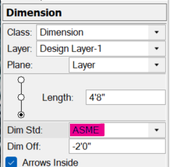
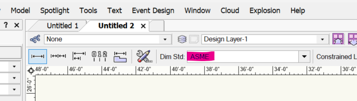
I suspect you have changed from Arch to ASME. to change the existing dimensions choose Arch from this pull down in the Object Info Palette. and to stop it from happening on new dimensions change it to Arch here. Both are easy places to accidentally click, especially the second one which is your culprit. Accidentally catching it while changing layers or editing existing layers is probably when it happened.
-
Thank you for showing me this. To do theses exact functions I have spent so much time using Vectorworks like it was a straightedge and compass doing geometric constructions as if I were one of Paul's colleagues 45yrs ago😁. The names of some of these tools say so little about what they do and the little icons don't reveal much either. I don't know what I would call it instead though. I need to go through the palette customization process again and investigate the uses of all the tools with what I know now. Between tools i didn't know existed and tools i use everyday that do things I don't know about or don't understand I could be busy for a while.
-
Loft Tool will not let me select a NURBS curve, 2 degree
jmcewen replied to MGuilfoile's question in Troubleshooting
Can you post a file with the curves in it? Maybe we can find the problem. -
Thank you. Skill at design, yes, but in Vectorworks there is still much to learn. I actually only discovered the create contours tool while working on this problem. I didn't realize the split tool worked on 3d objects until 2 weeks ago (the basic palette has always been 2d palette in my mind.) I have been drawing for about 18 years (about 13 years as a primary responsibility) but I am still finding things I don't know about that immediately become integral to my process. All this time and I still think of myself as a novice. There is so much I do not know about so much. A good bit of what i see on the forum here is gibberish to me until I need it enough to learn it. The one advantage I think I have over a lot of 3D modelers is the amount of time I have spent building in real life. I started as a theatre scene painter, then started building so that projects would get to the paint department in time to be painted, then started doing breakdown drawings to get things to carpenters in time to be built so they would get to painters in time to be painted, and now I am designing so that things have time to be broken down in time to get to carpenters in time to build to get to painters to paint....
