jmcewen
-
Posts
112 -
Joined
-
Last visited
Content Type
Profiles
Forums
Events
Articles
Marionette
Store
Everything posted by jmcewen
-
My approach would be to build it as 3 solids. The first would be a tapered extrudeup to the break line you have drawn below the crotch. Then I would extract the top face of that extrusion and birail sweep it across 2 polylines traced from the elevation view to complete the first branch. Repeat with the same base ellipse and a new pair of rails traced from the other branch to complete the system You could also do this with a loft. Or you could do an extrude along path but tuning the taper will involve some trial and error.
-
Is this your dome that is getting installed today in a shipyard in Ancona Italy?

-
Just 3d model. Once i get it looking like i want, I will make the necessary compromises to 3d print some of it.
-
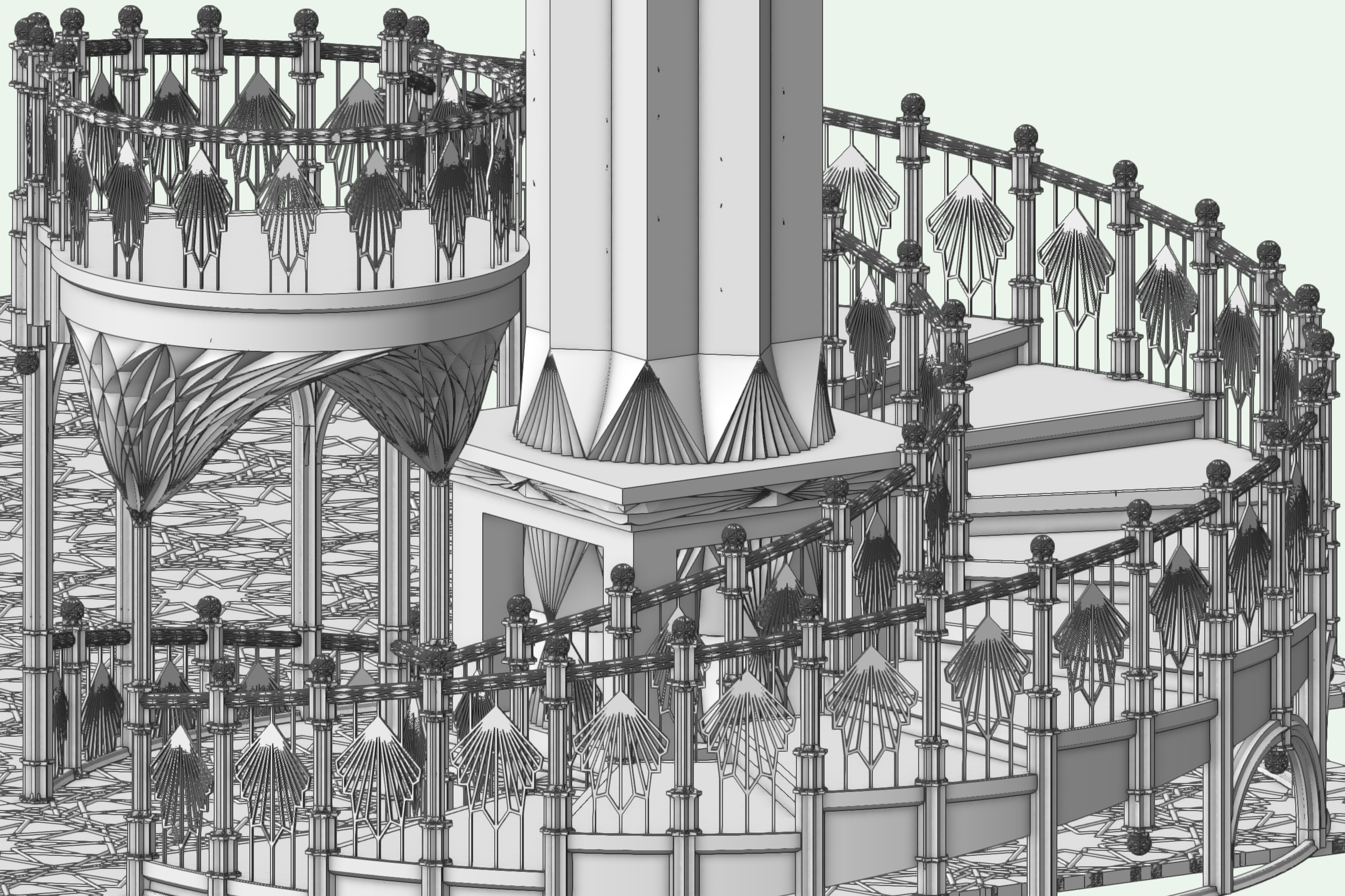
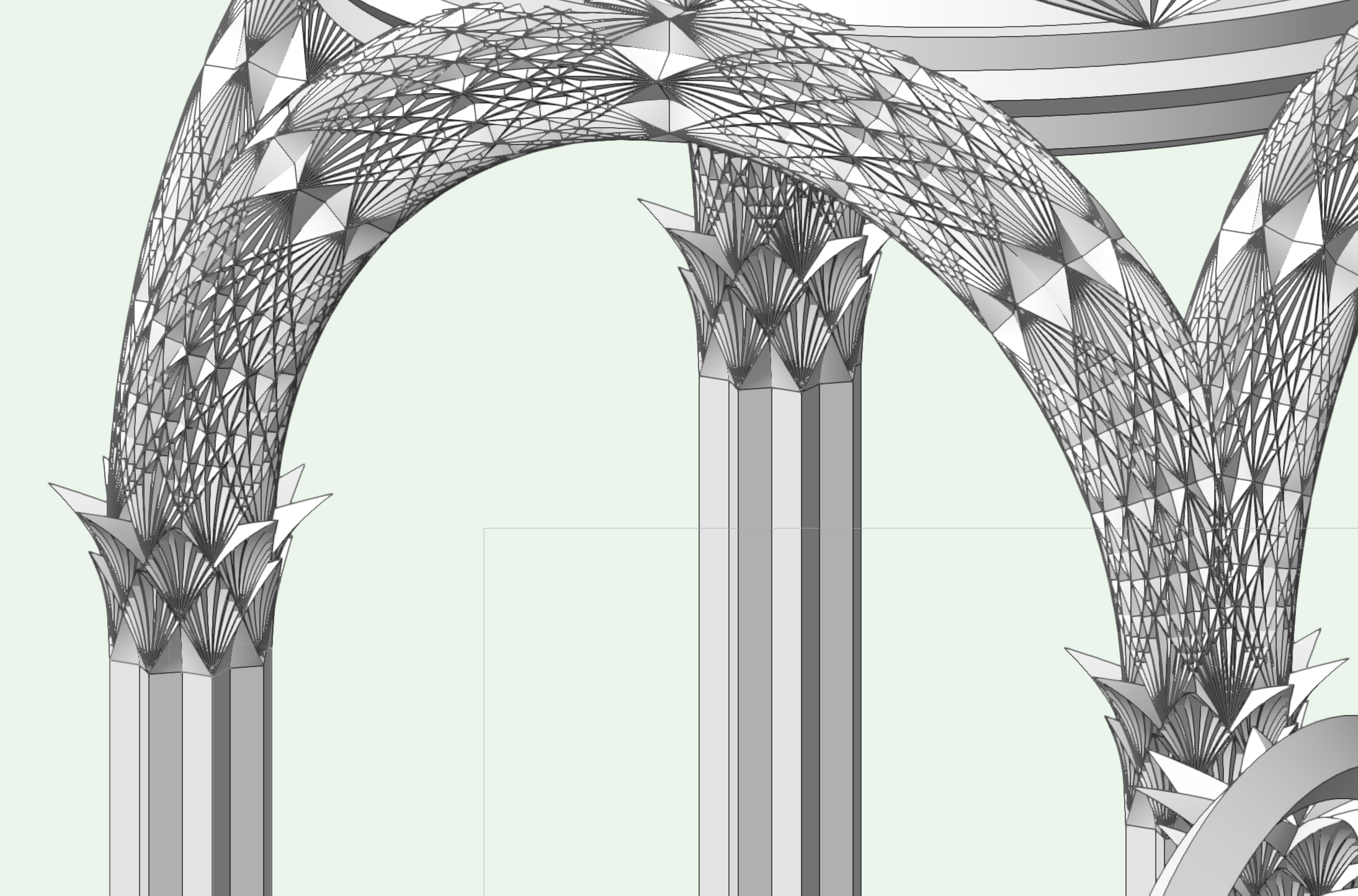
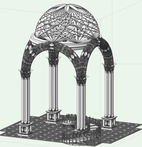
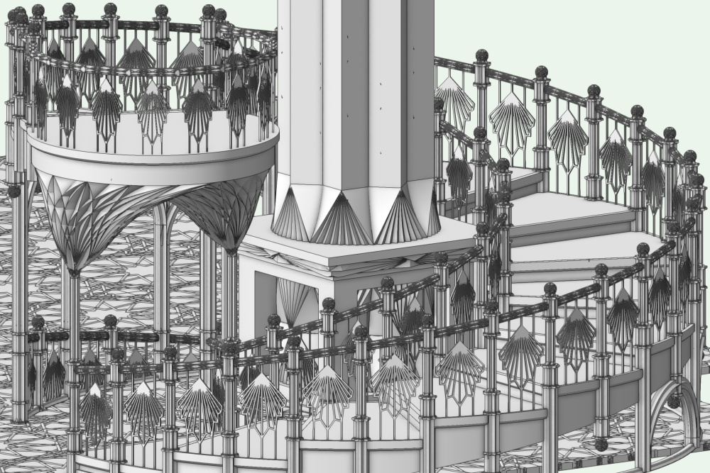
Polygon heavy doesn't begin to describe it....Haven't tried NURBing out yet. This has been a personal project of mine for a while-- decided to design something as I learned to use the tools and workflows that were never necessary in my previous career. Work has picked up, though and I have not been able to get back to it for a couple months. This is just a part of it-- working on a whole cathedral.
-
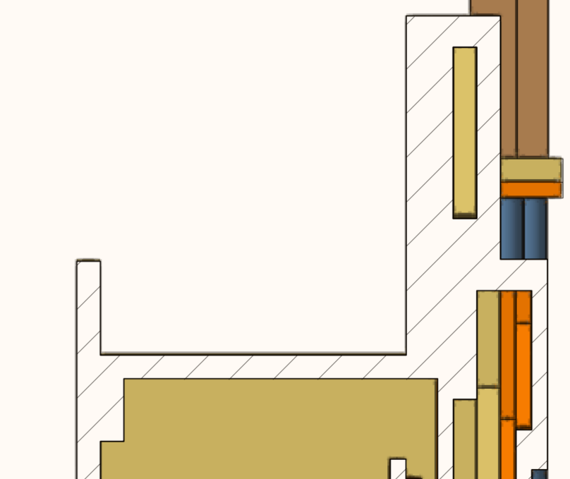
Using the deform tool in this way will absolutely work. The arches below were produced by repeated use of this method, stacking increasingly twisted square extrusions on top of each other so they occupy the same space, then bending them into an arch as a single unit once I achieved the look i wanted in a single straight piece. The geometry is imperfect, but it is close to being consistent. However you can probably spot some corners that no longer line up after repeated bendings. For your forged iron look, I doubt that any inconsistencies will really be a detriment to the final look.

-
I once again advocate for the UTechsmart Venus, which is nearly identical to the Redragon Impact Elite. I recently moved to the Redragon Legend. 23 programmable buttons on the Legend (counting the lmb,mmb, and rmb.). Fewer on the Venus/Impact Elite. Both are available in black or white when I last checked. The Redragon models have some additional red on them. They might not have the premium feel of your Rat or Razer, but will be far less expensive to try out; all should be in the neighborhood of $50. Razer has a model with 12 thumb buttons as well, though I have not tried it. The thumb buttons are easy to keep track of if 9 of them replace your numpad.
-
Will stitch and trim surfaces take care of this? If not, convert to mesh. Then select one face with the push/pull tool and move it by a set amount that is easy to remember like 1". Then move it back by the same amount so it ends up where it was to begin with. Usually if the mesh is complete, this will convert the mesh to a filled generic solid. It doesn't sound like it should work. I don't know why it works or who figured it out, but I do this fairly often. If the mesh is incomplete, i.e if there are gaps, it will do nothing.
-
Map those keys to the thumb buttons on this mouse so you don't need to move your hand. It took surprisingly little time to grow accustomed to the location. The numbers are arranged differently from the keypad so you will need to edit the mapping, but it is fairly easy.

-
Is the intent to fold the linework on at its normal size or do you want it to look "correct" from a particular view point like an anamorphic image? The first option will end up being a series of compromises, fudging, and muttering "close enough" I expect. If you are looking for the second option, set your working plane to your preferred view with the polyline placed on top of your bench in your preferred position in the screen plane. Extrude your polyline, then use the analysis tool to extract the curves from the surface of your bench (and whatever wall and floor objects are behind it.) When viewed from any direction other than the view you worked from it will be distorted, but from your chosen direction it will be perfect, and you will not need to bend anything.
-
Alterations to a 3d arch without losing resolution
jmcewen replied to Malcolm Woodruff's topic in General Discussion
Note that the settings on your viewports can be different from what you have set in the model space. If you have trouble with curve quality in the sheet layers as well, check each viewport's OIP under the "Background Render Settings" button. This opens the same render settings dialogue box but only applies to the viewport. -
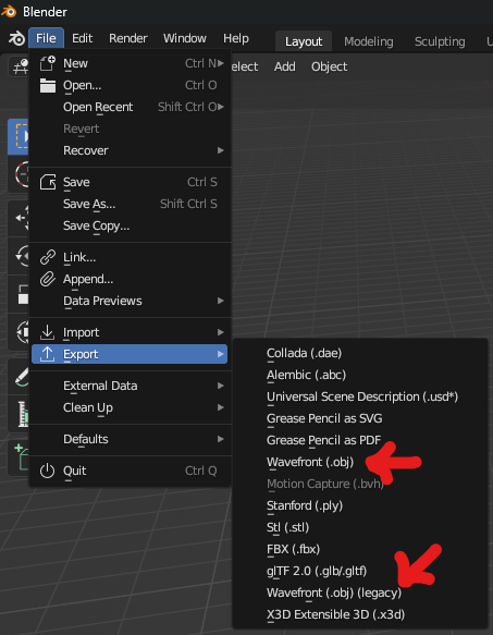
I am by no means an expert on this, more of a gentleman amateur to be honest, and my workflows are probably backward and upside down from anything that makes sense to a professional. Take my advice with a grain of salt. OBJ is hidden a bit. It is listed under Wavefront, so if you are looking for anything starting with "O" you will miss it. I still have not learned anything in Blender. I finally have too much work to stop and study tutorials, and the little bit of learning I had managed is now all fuzzy and forgotten.
-
Why can I not draw a 2D object in any orthographic view?
jmcewen replied to MGuilfoile's question in Troubleshooting
Sure, but this is an extra step. I tend to do all my playing at once, skipping from view to view. I can set the working plane every single time I change views so that I can draw my crop shape for every single viewport, or I can set to screen plane one time, and never need to think about working planes again until I want to model more. What is the value in phasing out screen plane as a standard option? -
Why can I not draw a 2D object in any orthographic view?
jmcewen replied to MGuilfoile's question in Troubleshooting
What was the reasoning behind phasing out screen plane mode? It was the fastest way to make viewports, especially if they are not orthographic. Almost every plate I make has at least one not-quite-isometric overview summary viewport because true isometrics always seem to line things up perfectly to hide important details. It would not change your working plane when you went back to drawing so screen plane is great for when you want to temporarily work at a strange angle. I keep turning on the legacy mode and a little while later find that the legacy mode has been deactivated again. -
Colour transparency and line weights issues
jmcewen replied to oliver.williams's question in Troubleshooting
Section viewports make use of a "section style" that you should be able to find in your class navigation pane. Section style governs any part of the viewport where your model crosses the cutting plane. You can right click on this clas and edit it. This allows you can change the lineweights and pen colors that are visible along the cutting plane, change fills or hatches that appear on the cutting plane, etc. -
TEXT ALONG CURVED PATH
jmcewen replied to DSmith2300's question in Wishlist - Feature and Content Requests
Add this to the list of seeming ly basic tools that could have saved me hours if I had realized it existed, but that I have always used a complicated workaround to achieve the same result. Maintaining that editability is a huge deal! -
There are times when I love having the 15 added and times that I absolutely hate it. When my drawings get a little too crowded and there are many things competing for those snaps it gets to be too much. But most of the time i am glad I have it.
-
Thank you @Jeremy Best. It hasn't happened in several days so I am hoping it was just a transient issue that sorted itself out. Followed might not be the best way to describe the behavior. When i moved the mouse , the SOD would pop up the moment I stopped without delay. it would also disappear if i moved at all, even as little as to try to click something in the display, but still it would immediately reappear after I moved. But if it starts happening again, I know the steps to take to figure it out now!
-
Thank you. Advanced Properties had run off the bottom of my OIP so I had not found it. This will save me a lot of time today. I have a ton of sections to plate, and I did not want to need to draw the object separations in the annotations!
-
I suspect this is a simple one that I have just missed. When I create a section viewport, every object along the cutting line appears in section as though they were a single object, with the hatch continuous across all objects. Is there a setting somewhere to allow the objects to appear separate? it seems there should be. That is half the point of a section viewport in my mind-- to see the layers of parts that go into an assembly.
-
Sometimes when I open a file, the smart options display pops up and follows my cursor. It has almost no delay before it pops up after moving. No tools are useable when this happens, including anything that is in the SOD. The ribbon is clickable. I can change views. I can change layers. I can change tools from a palette, but they are all non-functional while this is happening-- I cannot even select objects. The only thing I have found to stop it consistently is to start a new document then switch back to the document I wanted in the first place. It happens most regularly when I open a backup file (I have suffered a few crashes lately), but occasionally from a regular file. I don't think I have seen it happen when opening the application without opening a file, but I cannot be certain of that. I don't use the SOD, and it is turned off in my workspace. I often stop and stare at my drawings when thinking, and I don't like to see it when that happens. I can remedy the problem when it arises, but does anyone have any thoughts on how to prevent it, or does anyone else experience this who can offer more info?
-
As always, we will have a hundred ways proposed to do something and every one of them will be 100% correct. Use-case, inputs, and client expectations make all the difference in the world. That model looks great! I would not want to be stuck trying to recreate those beams in the real world though!🤪
-
I am learning I like deform when I am making something new that I am in control of the final look. It is fun to push and pull and say it looks like what I intended. Matching existing with deform is a little more difficult, and I am learning the value of NURBS processes in that use case.
-
@VIRTUALENVIRONS is more NURBS friendly than I am, but another way to find those curves if you are working from flat orthographics is to trace 2 separate views and extrude each one, then arrange them so they intersect appropriately. At that point you can use analysis to find the curve at the intersection. You might need to repeat a few times to generate enough curves to generate a surface, but the process is pretty quick, and judicious planning of what you trace for each extrusion can yield multiple curves to save some repetition. I have often gotten a PDF of orthos that were plainly derived from a 3d model, but I was told the models didn't exist, so I have done some variation of this process a lot (but I didn't know about analysis when I was at that job so there were more steps involved!)
-
I have taken OBJs out of Blender successfully before with textures intact. That is about all I can do with Blender so far, and was the whole reason i downloaded it in th efirst place-- as an alternative route to fix broken textures in downloaded models.
-
The Deform tool works great when it works. It fails a lot though. It amazes me what it will joyfully plow through, and it equally amazes me how it can stumble on tasks that appear to be simple. Note that the deform tool will also always result in a generic solid, thereby deleting all history data for the object. You will not be able to edit any additions, subtractions, fillets, chamfers, etc after the operation. Consider your order of operations when planning your model with this in mind. this should only apply to each object, though. Each batten should end up a generic solid and the concrete should be a generic solid.