Tom W.
-
Posts
5,067 -
Joined
-
Last visited
Content Type
Profiles
Forums
Events
Articles
Marionette
Store
Everything posted by Tom W.
-
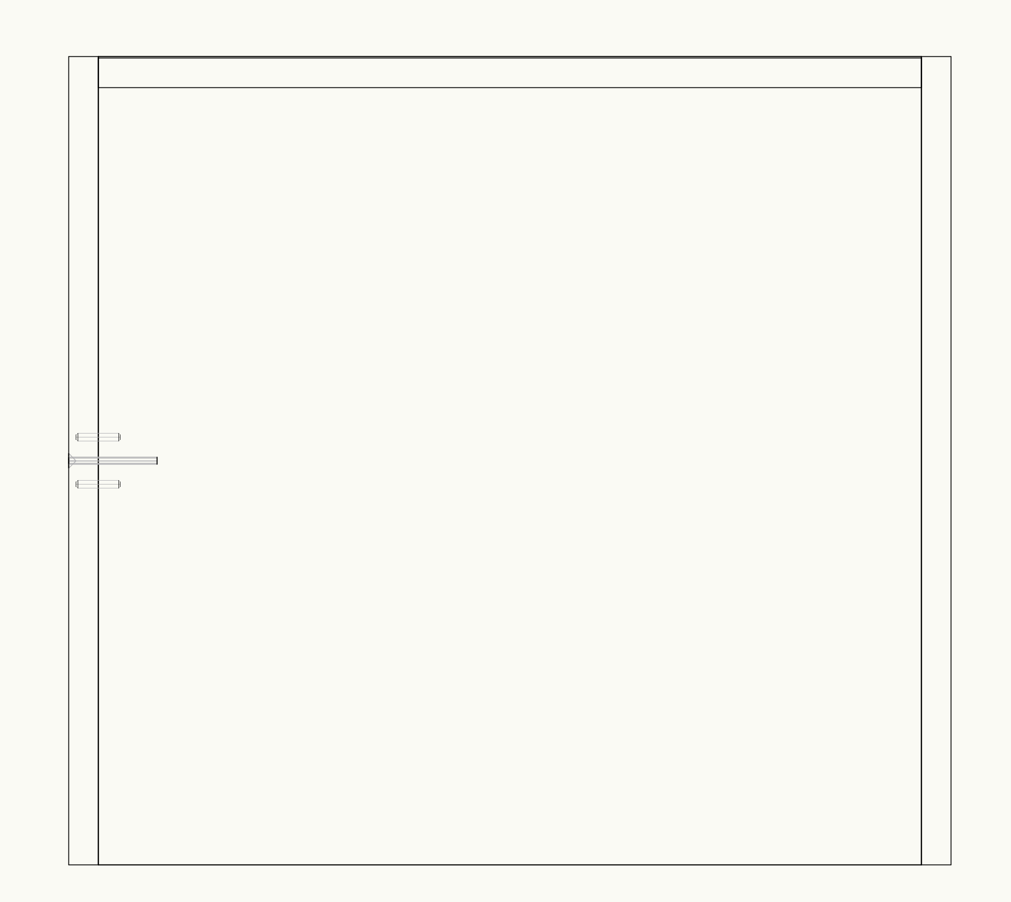
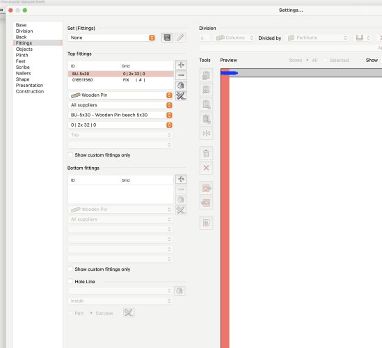
I am using the Interiorxs demo version + I can't see a way to create your own grid in the Fittings tab. Is this another shortcoming of XS over the full CAD version...? This: Gives me this: Which is one-off of what you wanted but without being able to edit the grids I can't see a way to move the dowels/screw up + down the panel + repeat it. @Blinkglitter is someone else who might be able to help.
-
Might be time to post the file...
-
Also, are the classes the Slab components are assigned to visible?
-
It looks like all the components are assigned to the stair class so it's not that. What are your settings in the Construction tab? Do you have 'tread thickness' + 'riser thickness' unchecked..?
-
Are your Tread + Riser classes turned off? Check the classes in the 'Graphic Attributes' tab for the Stair. 2D attributes + 3D attributes are controlled separately.
-
Yes I have a ProMap template file covering the 8km x 9km area I mainly work in. It is a 2D file: just lots of lines/polygons (no hatches) + only 13MB in size. But it is quite laggy on the DL zooming in + out + navigating about. Plus in other files hatches like this will really slow things down: But this one has 379 levels so I guess I've only got myself to blame... Other times I've placed too many Plant symbols (with too much 2D linework) in a drawing + things have ground to a halt... On the other hand I can cram as much 3D geometry in as I like + everything's absolutely fine!

-
I have an A1 size sheet with six vector-only viewports on it. The sheet DPI is 72 + if I publish it with the resolution set to 72 DPI with file size reduction set to 'None' the resultant PDF is 13.9 MB. If I publish it again + set the file size reduction to maximum the resultant PDF is still 13.9 MB so no benefit there. If I set the export resolution to 48 DPI however the PDF comes in at 3.6 MB but the hatches have gone a bit haywire in the process. I checked the fill on the VPs + half of them were set to None so I made sure all of them had a solid fill + republished at 72 DPI but the PDF was still 13.9 MB so again no benefit there either. I thought I read somewhere that the emphasis on maximising 3D optimisation meant that 2D performance had suffered as a result but I know nothing about these things... I know I receive PDFs from others containing vast amounts of vector based geometry (maps for example) + there are no issues with the file size or anything else but when I try to create the same type of PDF in VW the files are enormous... So is it to do with how VW deals with 2D geometry compared to other software?
-
Does this just affect image-based graphics or will it reduce the file size of line-based geometry as well...?
-
Everything on the design layer is in fact drawn at 1:1. So if you want to be drawing in metres you need to go to File > Document Settings > Units... + select metres as the units. In fact set up everything the way you want it + save the settings so you can apply them across all files. The design layer scale is more a preset zoom level which you'd normally set to the same scale as what your sheet layers will commonly be so that you are seeing things on the design layer at the same scale as they will be printed. There are various threads on this such as: I'm not really sure why your vehicle symbols, doors, etc are all so small in your screenshot... Did you resize them to make them that small? The cars look like they're 5-6mm long...! This is nothing to do with design layer scale. Scale really only comes into play in viewports.
-
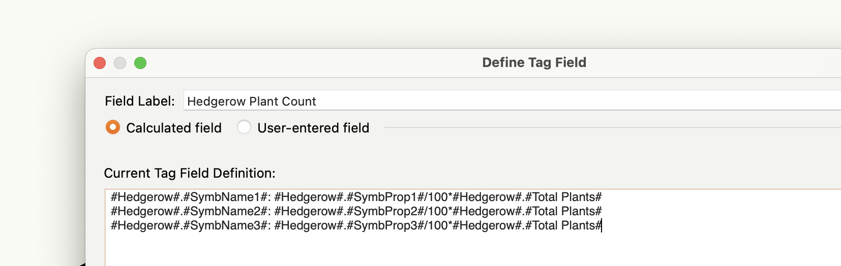
Thanks. Out of interest is there a reason why 'Hedgerow'.'__SymbQuant1' etc isn't included in the 'Parameter Name' drop-down in the 'Define Tag Field' dialog? Isn't it quite a useful thing to be able to report on? Or is it excluded because as you say, the standard way to measure quantity is per linear unit? Thanks.
-
Yes because it affects navigation/zooming on sheet layer too...
-
In this screenshot you are using the ISO-03 Dashed Spaced Line Type but the Line is only 7.3mm long which is too short relative to the length of the dashes. Either make the line longer or edit the Line Type to make the dashes/spaces smaller. In the second screenshot the line is 10.56mm long so it's probably the same thing but hard to say without knowing what the HIDDEN Line Type is. The Pen is not by class so you're not using ISO-03 Dashed Spaced which is possibly your intention. Make the pen by class in the Attributes Palette to do this.
-
This is the killer for me. And just loads of 2D linework generally. Images I can easily compress afterwards using ILovePDF but the big 2D PDFs I can do nothing with after the fact. But then I've got consultants sending me 30MB+ reports so I figure what's so bad if I produce the odd 15MB drawing myself...? Not ideal but at the same time there is no restriction on uploading files this size to my LPA portal.
-
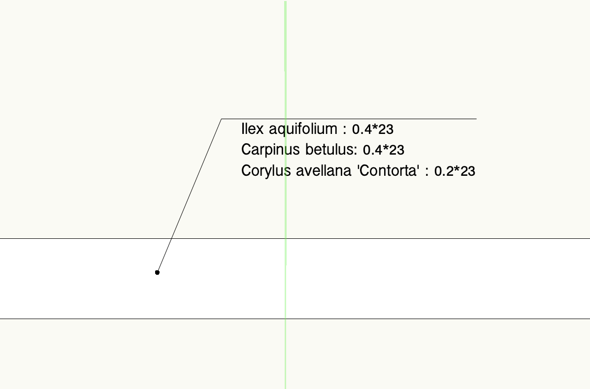
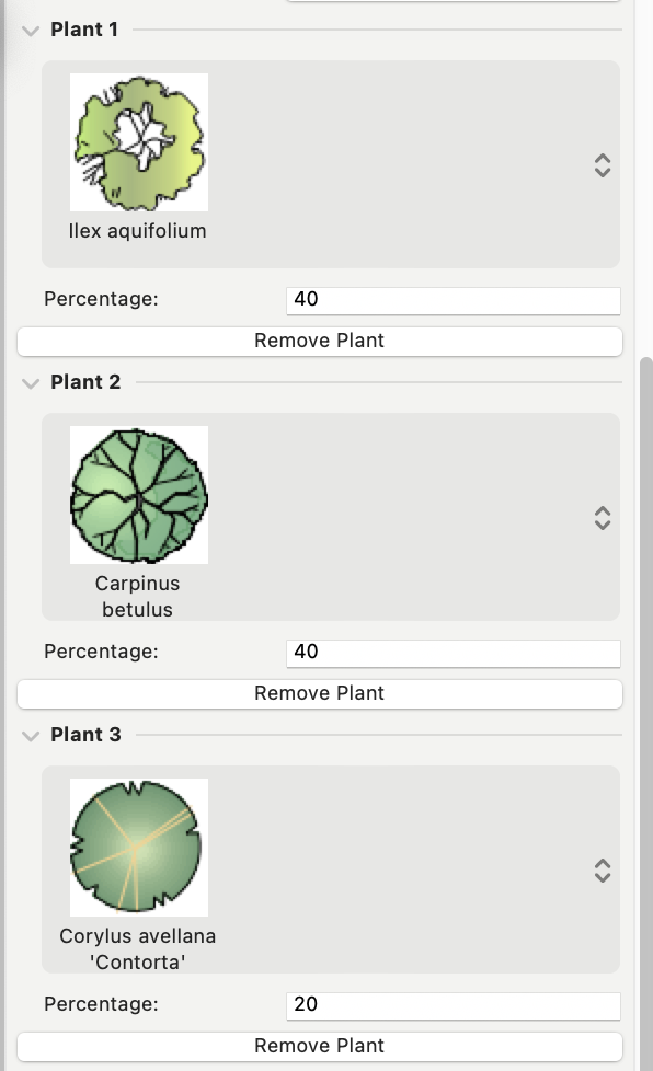
Thank you yes I do have a vague recollection about seeing this but I think it all sounded very complicated at the time so I scurried away + didn't investigate further... But now I've seen it in action I reverse my position! I will play around with it thanks for the link. BTW both tags seem to be returning whole numbers whatever size I make the hedgerow. I noticed at the beginning that #Hedgerow#.#Total Plants# was always returning a whole number: so if my Hedgerow has an area of 38.621 sq m + the plant density is set to 1 plant per sq m, it returns a total plant value of 39 rather than 38.621. Is this a function of it being defined as text? And is this characteristic retained when you apply the Value function? Or does Value convert Text to Integers by default? And why if you say that #Hedgerow#.#__SymbQuant1# is defined as a Real does it not return 15.4484 plants for example instead of 15 plants...? Sorry for all the questions + thanks for taking the time to talk me through all this. Also, I hope the tag is of some use to @Laura Stone!
-
Brilliant thank you. So did you find these by searching for them somewhere or was it just trial + error + years of experience, sixth sense, etc?! Can I have your brain when you retire? 🙂
-
Sure thank you: Hedgerow Tag Test.vwx It's funny: in the process of copying the tag + hedgerow into a clean blank file the /100 part of the formula has stopped working. Why does it work in one file but not in the other...? Be glad to hear your thoughts thanks for looking at it
-
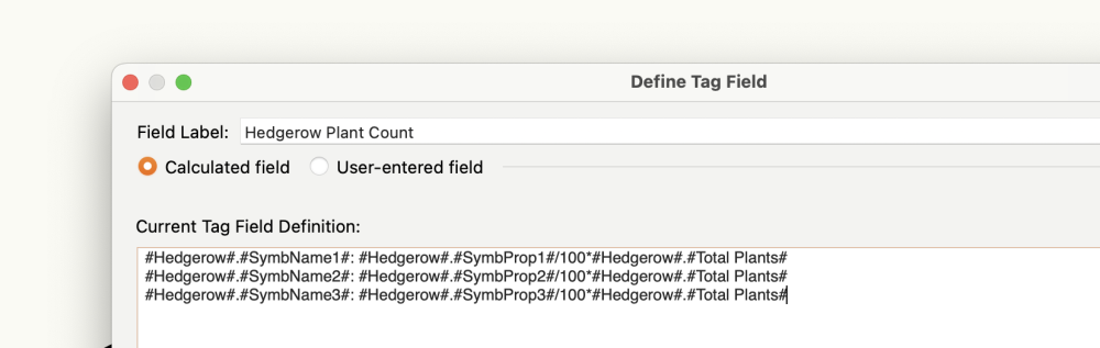
I was hoping this might do it: But it doesn't do the maths unfortunately: But perhaps @Pat Stanford or @Nikolay Zhelyazkov can say how it should be done! This is the Hedgerow settings:

-
I struggle with reducing the file size of PDFs with lots of 2D geometry too. All I know to do is lower the publish DPI: 72dpi at a minimum + sometimes less if I can get away with it. But often I end up with 12MB PDFs + have to live with it. Be glad to know if there's anything else I could be doing.
-
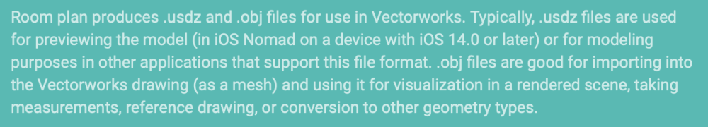
 @inikolova thanks for such a helpful explanation! I tried doing a room plan scan just now, at home where I have internet, and the .obj file looks identical to the .usdz version: there were no textures generated with it @jeff prince...? The only difference I can see is that the model consists of a single mesh whereas in the .usdz version each wall is a separate mesh. Interestingly, I can convert the separate .usdz meshes into Generic Solids one at a time then add them together whereas the single .obj mesh won't convert into a solid... So I think going forward I will ignore the .obj file (if it's generated at all that is) + just work with the .usdz file... And if I want a textured .obj model I need to use Scaniverse, etc right? I have also been playing with 'Create a point cloud with Lidar' (Nomad). The point cloud that Nomad generates seems to have many more points than the Scaniverse version (2,000,000 compared to 500,000 in my case) so I guess that means I'm better off producing point clouds with Nomad?
 -
Can anyone suggest a reliable method for 3d scans of venues?
Tom W. replied to grant_PD's topic in General Discussion
@Claes Lundstrom did you stitch these 25 scans together by eye or is there a more precise method for aligning them within VW? thanks -
How do I chang the glazing in a curtain wall door?
Tom W. replied to K.E's question in Troubleshooting
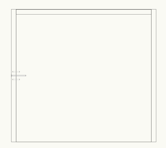
I don't use Curtain Walls much. I think I have just inserted Doors in Top/Plan the conventional way. When I try right-clicking in 'Edit Frames + Panels' mode the options are greyed-out: How do I insert a Door this way instead? Thanks!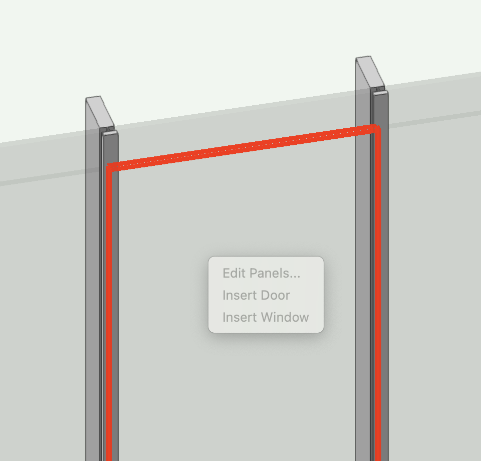
-
How do I chang the glazing in a curtain wall door?
Tom W. replied to K.E's question in Troubleshooting
You need to go to the 'Classes' tab in the Door Settings + see what class is selected for 'Glazing'. Then either replace this class with the appropriate one or edit it so it has the same texture as your Curtain Wall glazing. -
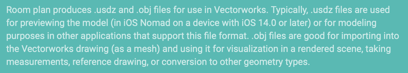
I have been playing with 'Create a room plan with Lidar' on Nomad. From the article linked above: I got the .USDZ file but no .OBJ file - presumably because I had no internet at the time? I assumed that once I had wifi the opportunity would re-present itself but I could find no way of sending a .USDZ file off to be processed into an .OBJ file. But seeing as I can import .USDZ directly into VW is there any reason to...? What is the benefit of importing the scan into VW as an OBJ instead of a USDZ? Why didn't I get an OBJ automatically as the article suggests? Why couldn't I generate one after the fact? Thanks!
-
Associative Dimensions and Parallel Constraints
Tom W. replied to rudybeuc@gmail.com's topic in General Discussion
In that case you can just have them as separate tools in the tool set, they don't all need to be children of a parent. Or add them to to your Smart Options Display if that's an easier way to access them. Although they do work on moving Walls in 3D via the Dim value, which was one of the examples in the orig post...- 9 replies
-
- 1
-

-
- associative
- associative dimentions
- (and 1 more)
-
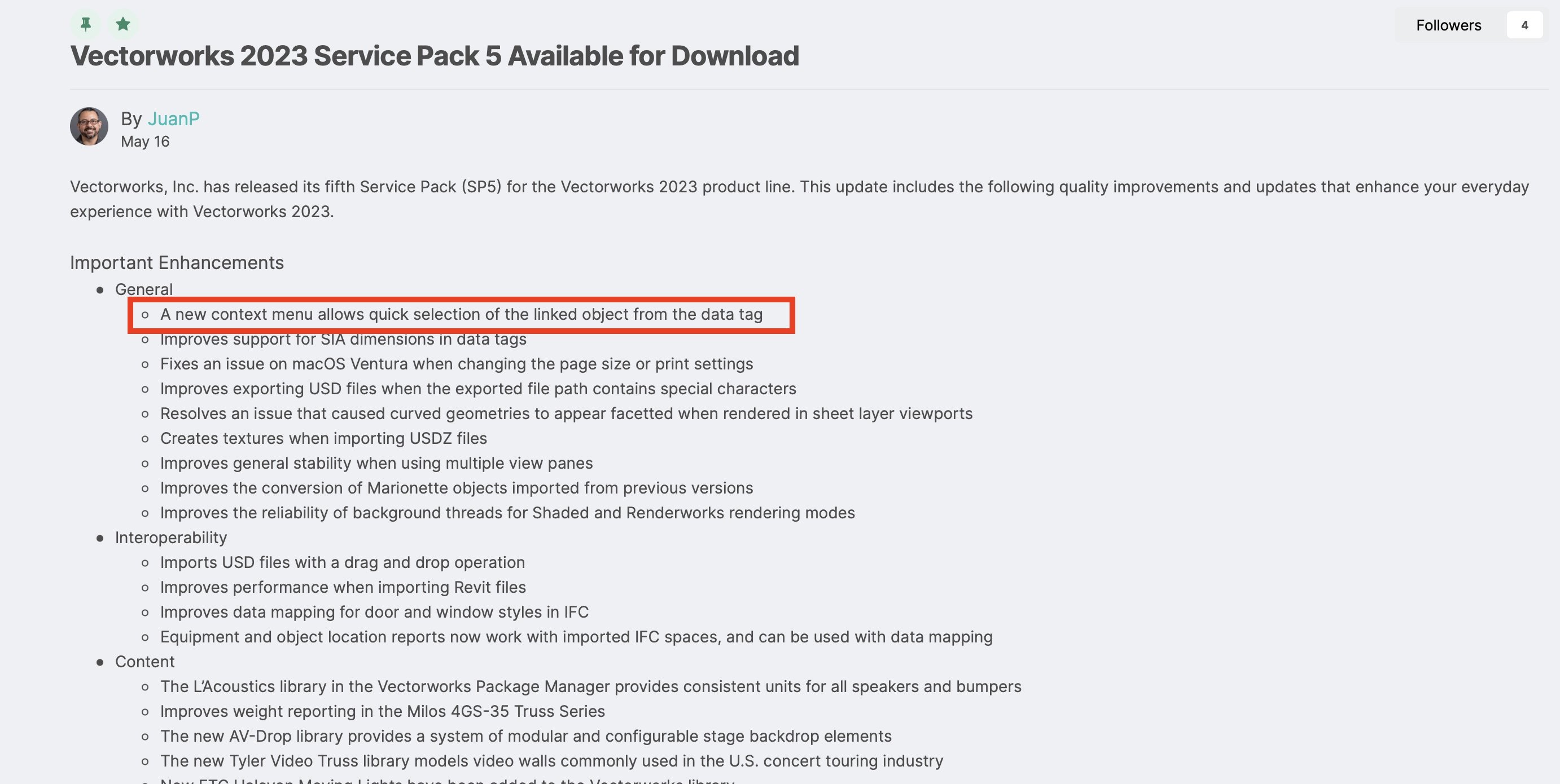
I agree this is great addition. It was new with SP5: It felt like no sooner was it discussed + requested than it appeared! Thank you VW!