Tom W.
-
Posts
5,083 -
Joined
-
Last visited
Content Type
Profiles
Forums
Events
Articles
Marionette
Store
Everything posted by Tom W.
-
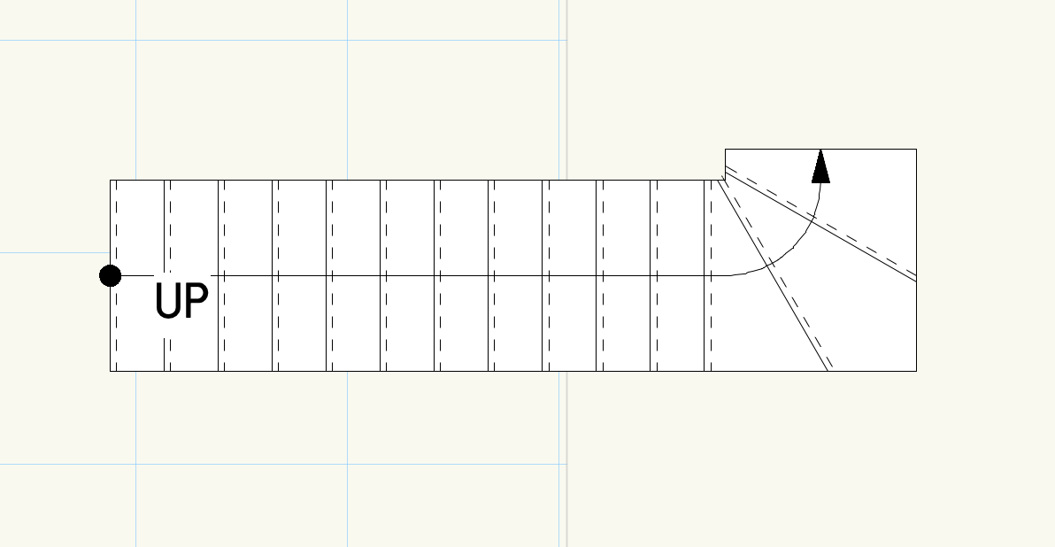
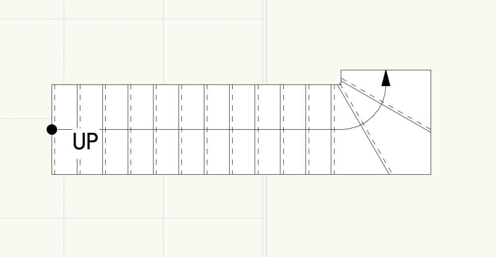
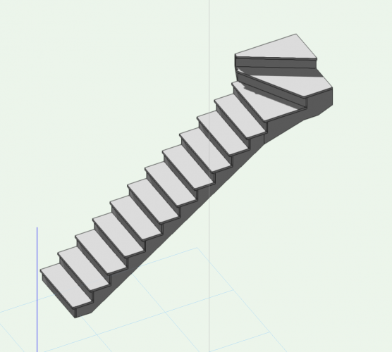
Is Custom Stair an option?
-

Forced to rename Hatch folder for same hatch ??????
Tom W. replied to Dubman's topic in General Discussion
Cool glad you got it sorted thought it sounded like a naming conflict 👍 -
Forced to rename Hatch folder for same hatch ??????
Tom W. replied to Dubman's topic in General Discussion
This is what I understood you meant but like I said, I can't replicate this behaviour. In your screenshot, do the various hatches folders actually contain anything or are they empty? -
How would I create detailed brickwork for the facade of a building?
Tom W. replied to Ami's topic in General Discussion
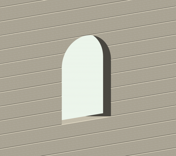
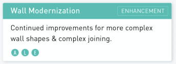
@CipesDesign is right the Create Wall Recess command is really let down by the fact it can't be used at the ends of walls. Perhaps this is something that the 'Wall Modernisation' enhancement in the road Map will address...? 🙏 It would be great to have the same flexibility for editing slabs available for walls also... Like @zoomer says, another option would be to use a Wall Hole Component symbol to create the main horizontal chamfered joints: This has the advantage of allowing you to use the wall tool + utilise all the functionality associated with walls: make them as long/high as you want, freely add doors/windows/openings/recesses, move them around, etc. Perpends (vertical joints) could easily have been incorporated into the wall hole symbol, I wasn't sure if you needed to show them or not. To do the detailing over the window I used another symbol that also incorporated a wall hole component to clip the wall to remove the horizontal joints in order to replace with the angled joints: This was a little bit fiddly + because it's specific to this particular sized opening would need to be remade if the opening size changed. But if you had several openings the same size once you've made the symbol it's then very quick + easy to reuse it on other windows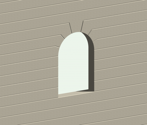
- 11 replies
-
- 3
-

-
- architecture
- walls
- (and 3 more)
-
Forced to rename Hatch folder for same hatch ??????
Tom W. replied to Dubman's topic in General Discussion
I don't see this behaviour. Copying an object from one file to another, if that object has no new resources associated with it, should have no bearing on the resources or the resource folders in the file you're copying it into. The only time I'd see what you describe is if I tried to import a Resource Folder from one file into another file which contained a Resource Folder of the same name: then there'd be a naming conflict + I'd have to rename the folder. Unless VW2021 behaves differently to 2020. Or I've misunderstood what you're saying -
Ha ha! Although be keen to learn more about these: Not sure what this means: ?

-
That being said any improvement to wall component wrapping would be a VERY positive step
-
No probably not v precise but looked a pretty cool way to populate a 2D map with massing models with a couple of clicks. If your city has only flat-roofed buildings that is... And you could find someone to supply the shape file in the first place... But how were you acquiring height info for your buildings/structures?
-
I can't find the videos now unfortunately. The way I understand it they are like OS maps but the polygons have data attached to them which gives you lots of options for modification, one of which is to make massing models from the polygons based on building elevation data contained in the file. This thread talks a little bit about it:
-
Hi Rick thanks. Depending on the process you use to create a hybrid symbol it will display differently in the Resource Manager (i.e. whether you select both the 3D + 2D components together in Top/Plan + select Create Symbol; whether you create a 3D only symbol first then edit the symbol definition to add a 2D component; whether you duplicate + edit an existing hybrid symbol). So if you’re making a number of different symbols you can quite quickly + easily end up with a variety of different display settings in the RM + find you need to tidy it up a bit to get them all displaying consistently. I recently made 20 plus electrical symbols that I wanted to display as Top/Plan view thumbnails in the resource viewer pane + right ISO Open GL thumbnails in the preview pane. To achieve the former was easy because I could select all the symbols + change them as one (in fact because of the way I created them they all displayed this way anyway). But to achieve the latter I had to click on each symbol individually to see what the preview display was set to, then if it needed changing it was four clicks to choose right ISO + Open GL. It was just wondering if there was a quicker/easier way to control what you see in the preview pane: like I said, ideally you’d select multiple symbols in the resource viewer pane then adjust the settings in the preview pane + have it affect all the selected symbols in one go, rather than having to adjust them all individually. I guess by defaults I meant something like an option in the ‘Create Symbol’ or ‘Symbol Options’ dialogs where you can specify how you want the thumbnail to display in the RM. But this just creates more settings – the first way would be simplest. This applies to Hardscapes as well. Like I say it’s not a massive deal, I just wondered if there was some clever trick I could be using to do it quicker. I actually found a Wishlist item from a couple of years ago regarding this but it didn't have many votes - it's obviously a niche area! Thanks
-
That's amazing you've surveyed that yourself. Very impressive. I thought maybe you were working off a shapefile which look amazing on the VW videos but not sure how/where you get hold of them (ProMap weren't v helpful)
-
@line-weight It looks fabulous. You gotta love a victorian railway viaduct. What kind of survey are you working from? Thanks for sharing
-
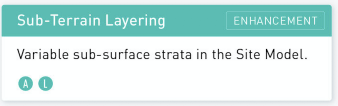
You'd rather hope not given the purpose of the command but hopefully someone more knowledgable can say. Be interested to know if bug or not By the way what is the model of, if you can say?
-
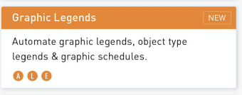
Yes you're right sorry: I meant to say that I just went around the model adding the various solids together until I identified the ones that wouldn't add together, and ended up with three separate solid additions, which could only be added together when they were dragged away from each other. In the process of pulling the model apart I found two Line objects which I deleted so not sure if they were part of the problem? Because you can't perform Add Solids on 2D objects? When I repositioned the solid additions I'd pulled away + ran Add Solids again it formed a single solid addition: Not sure I put the objects back in quite the right place. And also because I performed multiple Add Solids commands it's a nightmare to go back into the history + edit. So sorry not much help but if you can dig out the line objects + delete them that might allow you to run the command on the objects all at once? Select Similar then Invert Selection?
-
This is probably no help whatsoever but I could add most of it together with the exception of the two objects I've dragged away as shown in screenshot Once they were dragged away from the rest of it they could then be added to form a single Solid Addition. I have no idea why they wouldn't add when in their original (correct) positions. Is the aim to convert the overall object into a single generic solid?
-
You need to add the dimensions in the VP annotations. Right click or double click on the VP + choose 'Edit Annotations'. Then the dim values will be world based.
-
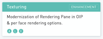
Just like to say I also think Andy Broomell's guides are excellent. I'd not seen this one on textures so thanks for sharing. And good to see your project
-
Is there a way to change the thumbnail settings for multiple resources at once in the preview pane of the Resource Manager? You can change the thumbnails of the resources themselves (in the resource viewer pane) en masse but not their preview thumbnails that I can see. Or a way of setting defaults so resources automatically display the way you want them? Not a massive issue obviously but does make a difference navigating through them if you have them displayed the way you want them + I seem to spend quite a lot of time going through adjusting them one by one...
-
That's a really good point. I'd kind of got used to re-Group sending the objects to the front then having to send them back again, but can see now the advantage of the Cut, Paste In Place method!
-
I tend to Ungroup (command-U), shift-click to deselect the object/s I want to remove, then command-G to regroup the remaining selected objects
-
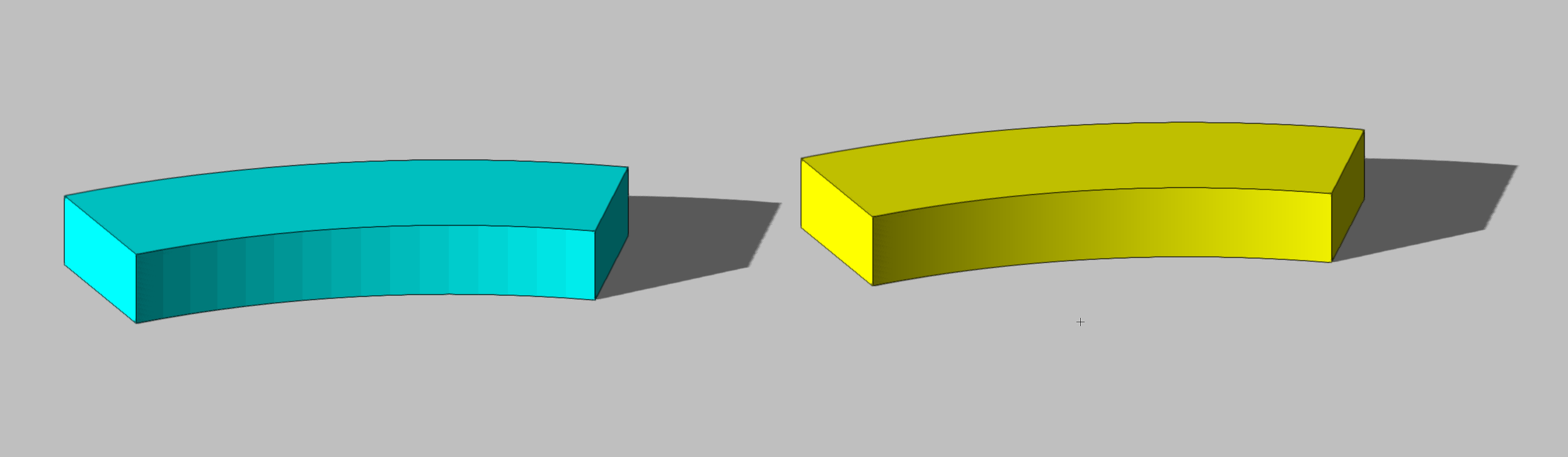
I thought I better check what I said about removing the facets on the curved floor object + I was wrong sorry: you can smooth the curve so much but not entirely. The blue object on left is a floor, the yellow one an extrude. I had no idea floors had this behaviour. This is with Open GL Detail + 3D conversion resolution both set to very high

-
Ok great. Not relevant now of course but on the faceted nature of the floor object I think if you go to VW Preferences > 3D tab > 3D Conversion Resolution you should be able to remedy this Also like I said earlier + bcd as well, something like this you're generally best making into a hybrid symbol so you get the 2D look you want + can easily be inserted into the drawing multiple times + can be saved in favourites for future use. Which is basically what you've ended up doing anyway by using a pre-existing symbol Glad you found a solution that works for you
-
Interestingly I just learnt (thanks to @michaelk) that if you run Convert to Group on a slab you find it's actually made out of floor objects, which makes it even more confusing why it doesn't share the same functionality in regard to texture mapping??
-
Hi @jpccrodrigues so pretty much what I was doing already + no trick to prevent it happening in first place. I can live with that! Thanks
-
Good question. I've had this too + wondered why it was happening. I just cropped the offending edge/s out like you say but be good to know why it happens + if anything can be done to prevent it