

trashcan
-
Posts
546 -
Joined
-
Last visited
Content Type
Profiles
Forums
Events
Articles
Marionette
Store
Posts posted by trashcan
-
-
@jeff prince seems like a similar issue but not exactly the same. Are you able to import PNGs with Alpha into VWX as resources?
Either way related to the same underlying problem.
Oddly, I can copy and paste them in - but then can't use them as resources.
My work around has been to use the Alpha + PNG and make a Luma Matte that matches the PNG. I use that Luma Matte as the mask for the PNG when I bring it in as a resource and turn it into a prop. Worked fine, none of the grey stuff happening. Though I haven't tried it in RenderWorks yet.
I've also found that if I bring in other images (say a floor plan reference) it masks the image prop for some reason. The work around for that problem has been to apply image effects on the floor plan reference and then toggle them off. Obviously a bug. Silly.
There seems to be a lot of issues with bitmap / images / import / export. Sometimes I wonder if this kind of stuff even gets QA'd...
-
Curious about this as well!
Mainly as a work around because importing PNGs with Alpha seems to be broken in VWX 20
However, the alpha does carry over when copying and pasting... odd.
-
Oddly, if I copy and paste that PNG from Photoshop to Vectorworks - the alpha shows up! But alas, I can't save it as an image resource so cannot reuse it as an image prop.
-
I have a PNG plus alpha image I created in photoshop. I can confirm it has alpha channel.
Per the documentation:

I am using a Mac.
When I go to import that image, here are the options in the dialog box:
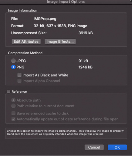
🤔
Bug? Or am I missing something.
-
You'd think that would work but

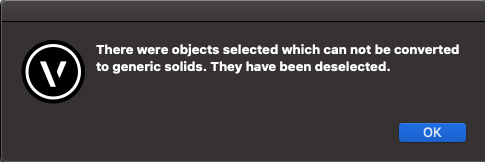
-
@markdd still works like a charm - follow up though - how do I convert that mesh back to a generic solid?
-
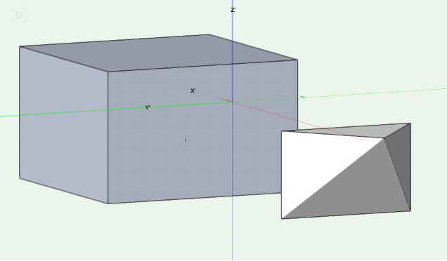
This is driving me nuts again.
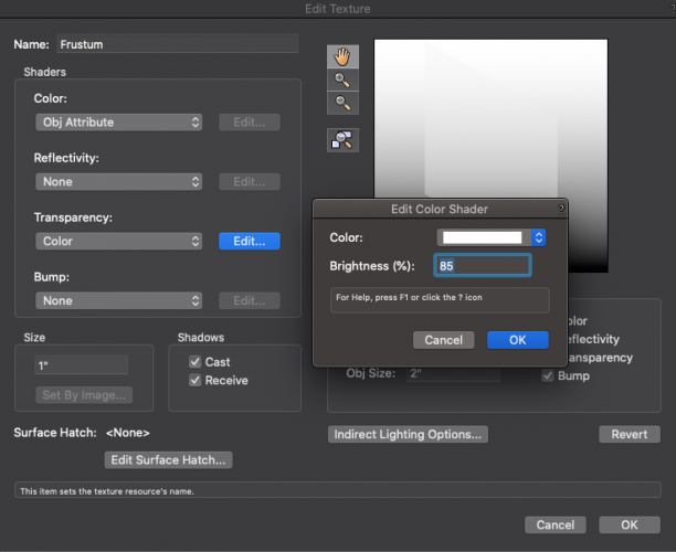
Pyramid is supposed to be transparent:

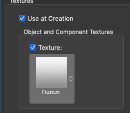
Texture details:
Class details:
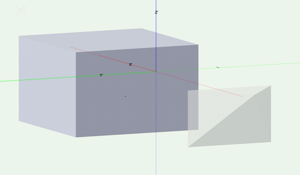
Pyramid should be transparent in OpenGL, but appears to only show as transparent using a RW style (I.e., final quality):

How do I get this to work with Open GL again? Or... is this a bug. Have restarted VWX etc.
-
@Taproot👍 three year old post saved me, thanks
-
Would love to be able to go deeper than 4 levels deep with subclass hierarchy. I'm sure I'm not alone here!
-
@cberg it's a workflow I have to use often for mapping on architectural stuff. 😭
It seems to me that there's a bug here somewhere. I've narrowed it down to a use case that always works (viewport wireframe) and many that don't (all other renderers). So at least there's that!
Other folks don't seem to have this problem - so wondering if it's version related or there's something else I'm missing. I've also contacted support but haven't heard back...
-
@cberg the issue is that vectors only seem to get exported properly if my viewport is rendering wireframe. Any other background renderer rasterizes the image.
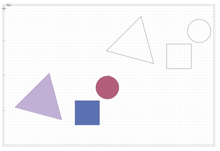
Here's a little example:
These bricks are all individual 2D objects, with a solid fill and a little pen stroke. If my viewport is set to OpenGL, in Illustrator (or Affinity if you go that route), it comes through as a rasterized image, not as individual bricks.
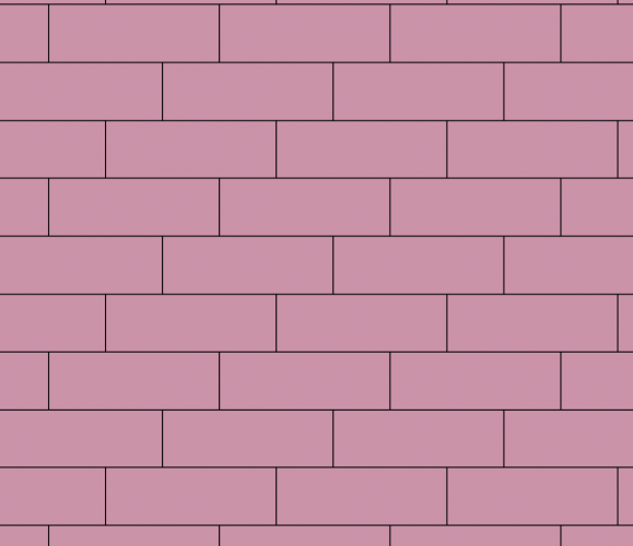
If I change my viewport background renderer to wireframe, the bricks comes through as individual shapes in Illustrator.
Oddly, I have a symbol in another viewport that in wireframe renders as a solid shape (with color) for some reason. Very confusing.
-
A little update from my end.
If I set my view to WIREFRAME, it exports properly. So that's good.
But I want to export solids as vectors... not possible?
-
@Pat Stanford noob question: how do you implement a script?
-
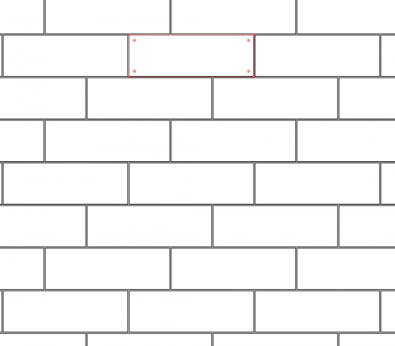
I'm working on a project right now where the tiling pattern of the bricks was originally drawn with 50% offset row-to-row and it has since changed to 1/3 offset row-to-row.
I've received an as-built and have imported it just fine, but I now need to scale everything to match with the grout. The simplest technique I can think of is to select all the individual bricks and perform some kind of "scale each". In other programs it's called "scale each" or "transform each".
The bricks are currently 1' wide x 4" tall. I'd like to make them 11 15/16" wide x 3 15/16" tall, but keep their center consistent.
It seems like it's as simple as
- Grouping all the bricks
- Duplicate the group
- Open the top layer group, select all bricks and subtract .083" from each side in the OIP (with anchor being the center).
- Open the bottom layer group and perform add surface. Then I have my grout.
- Then I can rescale everything so that the bricks are back to their true 12" x 4"
Does that sound right?
-
@fuberator sup man good to see you on here 👋.
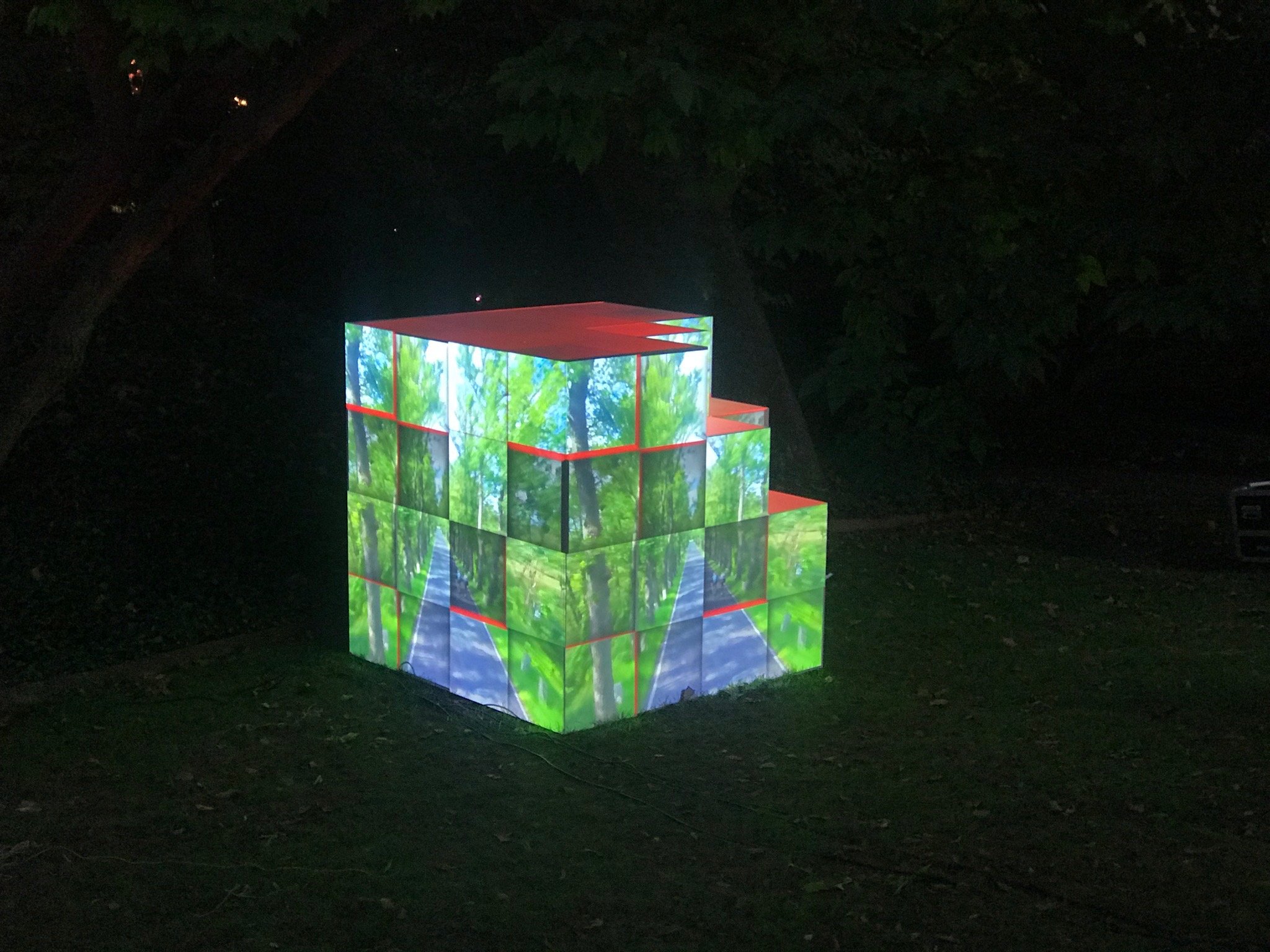
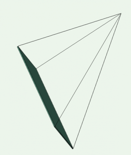
I'm not using the projector screen tool so don't have the tilt options. I'm using projector symbols and then manually drawing out the projector cones using good old frustums. Most of my projections surfaces aren't flat planes so I kind of need to do that (unless you have a workflow recommendation!).
-
Oddly, if I copy the solids into Illustrator or Affinity (literally copy and paste), I get the same rasterized versions of the shapes. If I switch my viewport to hidden line and copy and paste, the shape data comes through on a copy and paste method:
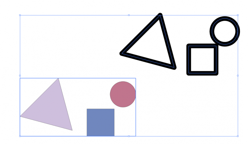
This is true both in Affinity and Illustrator.
So a workaround here is to switch your viewport to hidden line and straight up copy and paste into your vector editing software. Unfortunately, this isn't always accurate but it's better than redrawing from scratch. I have tried this with more complex shapes and it is a consistent solve, but be prepared to do some repairing 😪
-
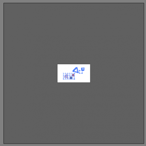
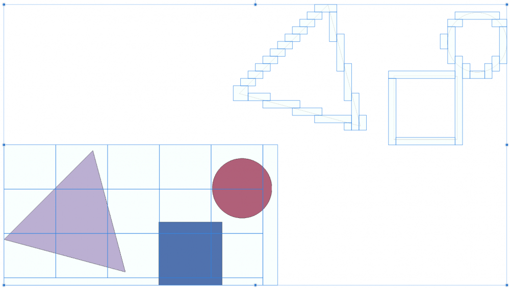
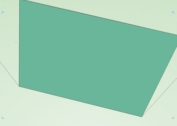
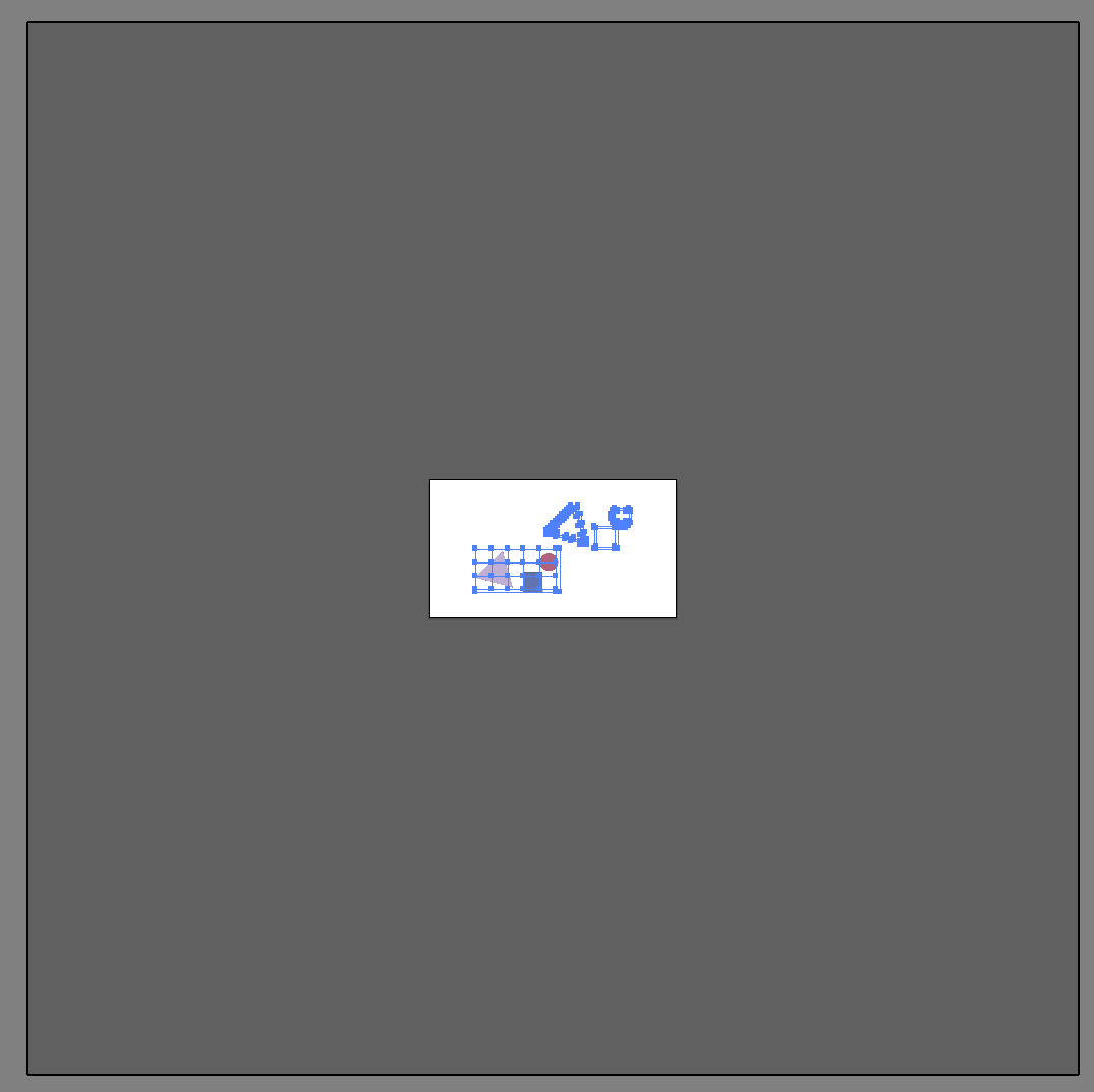
@Claes Lundstrom - the export dims are fine. my sheet layer is Arch D.
The big grey box here is the Illustrator drawing area on import, the white area is Arch D.
When an image is bigger than the drawing area on import, it will still open in AI. But that isn't the problem here:
-
Weird. I'm using VW20 SP3.1 - have jumped through all the hoops I can find and still am unable to look at the shapes as anything other than a rasterized image. Have contacted VWX support and will post my findings here.
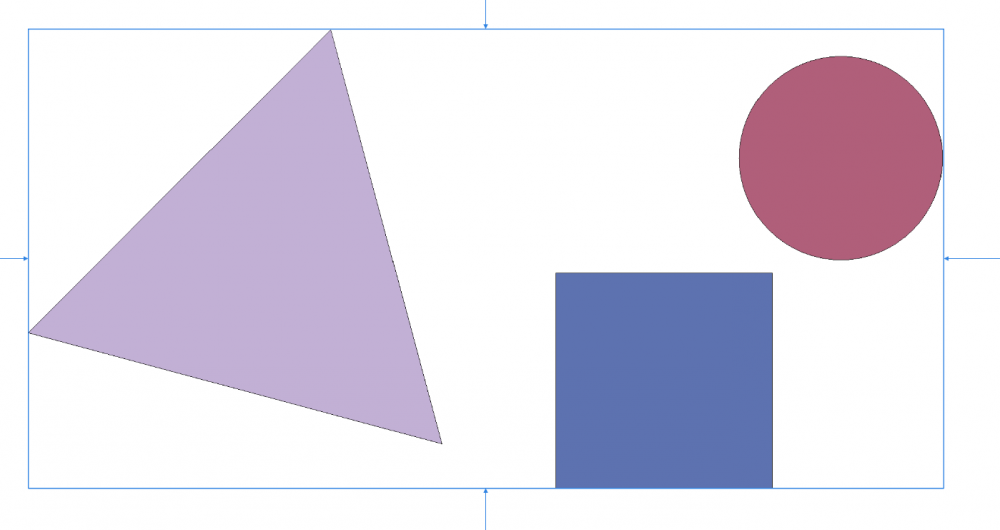
I wondered if it was something like the Render style, so tried exporting this (EPS):
This is what it looks like both in Illustrator and Affinity Designer:
Really odd behavior!
-
@Claes Lundstrom For due diligence, I tried this using affinity designer and the image still came through rasterized. Are you using VW18 or VW20?
-
Re: Rotating the image - I'm having trouble following that workflow - are you saying to use the rotate tool or work off that dummy plane I've created?
Re: Spread angle 2*.5 = 1?
-
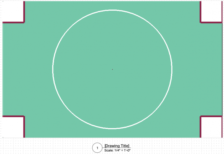
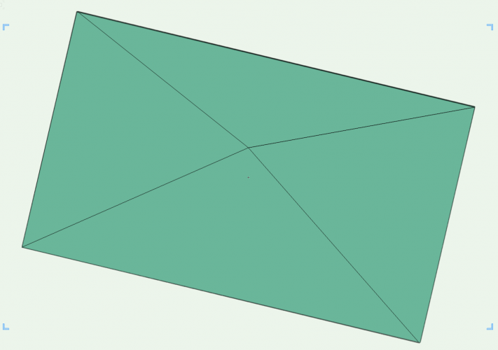
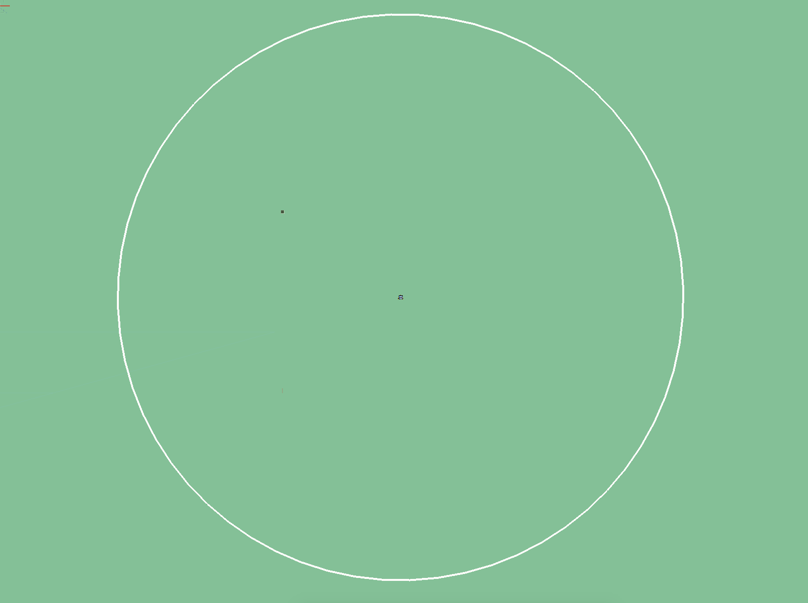
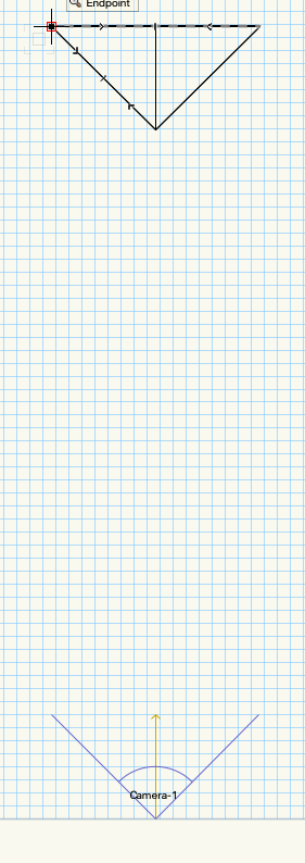
In a simple config I could easily enough match the PV object to the frustum. Here's the target area:
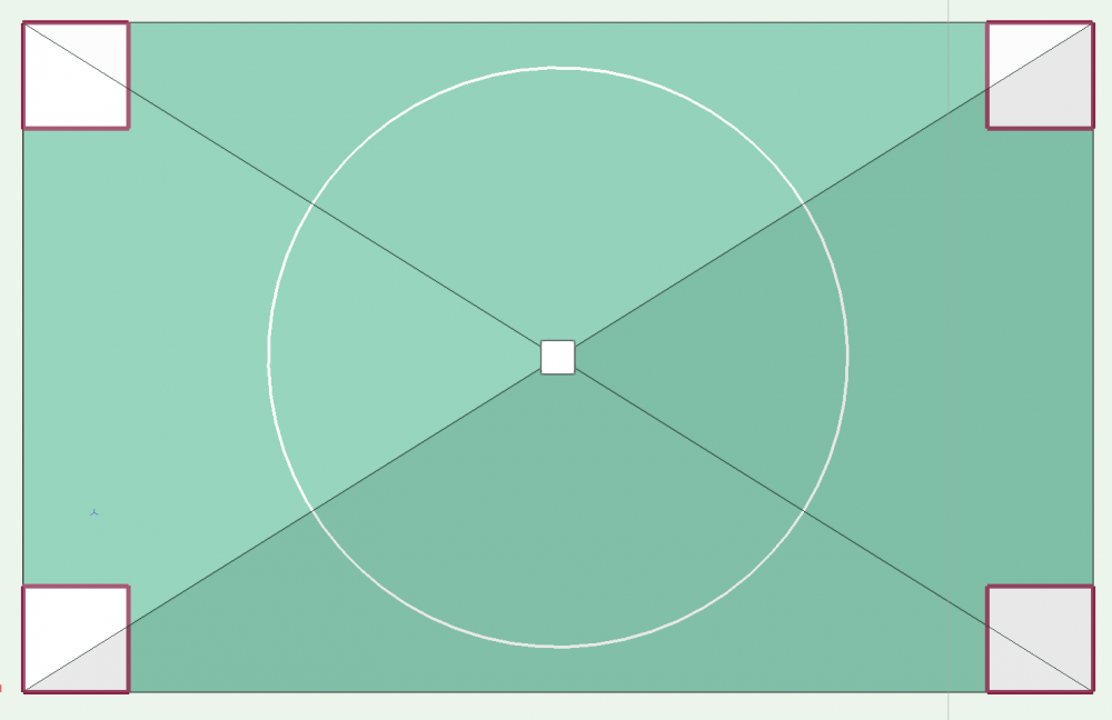
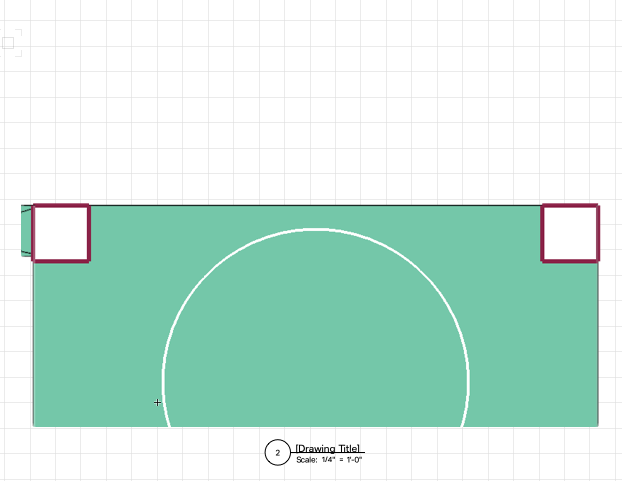
View from projector looks like so - not quite what I expected:
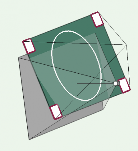
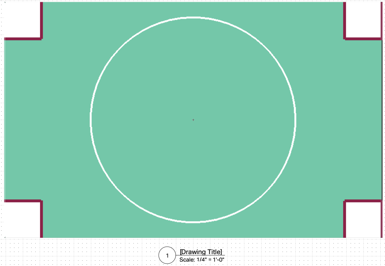
After clicking match camera as you described - I couldn't see anything at first so turned my projector into a locus point:
This process gave the right results with the odd part being that the view from projector wasn't showing what I expected. Or maybe that's correct? Either way got to the results I wanted on that use case.
I imagine there isn't a way to accommodate shift (I.e., -50% Horizontal)? My guess is no because cameras don't work that way.
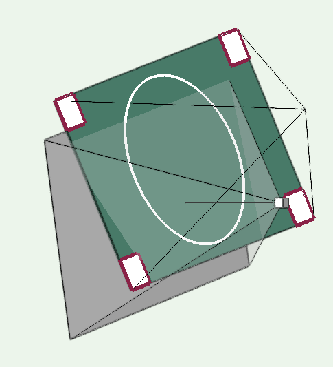
When I have a target surface that is rotated on all three axes, I'm finding it difficult to match:
Normally, I would use the target as a reference point / working plane but that doesn't seem to work because it's a hybrid symbol.
I was going to ask you how to calculate Lens to Spread Angle - but it looks like it's built right in to the Projection Viz Tool. What's that formula? Can't find it anywhere and am curious.
Any ideas?
-
I wonder if this is a bug. I know it has been a bug in previous versions of Vectorworks.
@JuanP is there a way to confirm if this is a bug or not?
I really need to export Vectors so I can get it out to our digital designers and not manually redraw all the shapes... the shapes... hundreds of shapes!
Here's a similar bug from 2015:
-
 1
1
-
-
Ah-ha I got lost on setting the Z height for the camera instead of setting the camera height and look to height at the projector position height.
Here's another one:
100% shift
Some pan
Some tilt
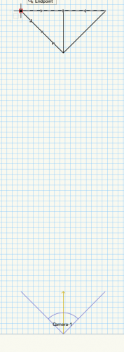
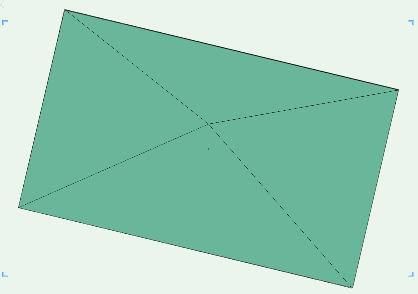
My starting point:
- Set the target green box as the working plane and save that as "target WP" (so I can easily check it against camera view)
- Set camera height to projector height
- Set look to height to center of projection field
So far so good, but: how do I tilt the camera down and rotate it to match? And dumb question: what is the Throw Ratio to FOV calculation?
Perspective:
Ortho:
-
@markdd I had that thought too, but as soon as you switch to ortho you can no longer set the aspect of the camera. Found a work-around though. Set camera ratio to custom 1.6, then switch to Ortho, then suddenly the aspect is there.
Though now the camera isn't at the frustum tip:


Reshape Generic Solid
in Troubleshooting
Posted
I think I figured this out. Re: @zoomer my reshape was watertight!
Seems a little backwards but here's a process that consistently works.
To move planes around as per my original post:
5. Reclose all the planes - turning into a 3D mesh auto converts to 3D polygons and then leaves them open polygons for some reason.
6. Convert back to Mesh
7. Convert from mesh to Generic Solids.
Is there any easy way to get rid of that 3D loci now?