Claes Lundstrom
-
Posts
241 -
Joined
-
Last visited
Recent Profile Visitors
3,864 profile views


-
Their OBJ files come into VW in scale though you have to rotate then to get Z face upwards. Point clouds work with DTM. Have used their STL to 3D print without doing anything, Nice movies can be generated in seconds. Their USDZ can be used directly for augmented reality on Apple devices without installing anything, Very fast. Pretty good indeed for a free app.
-
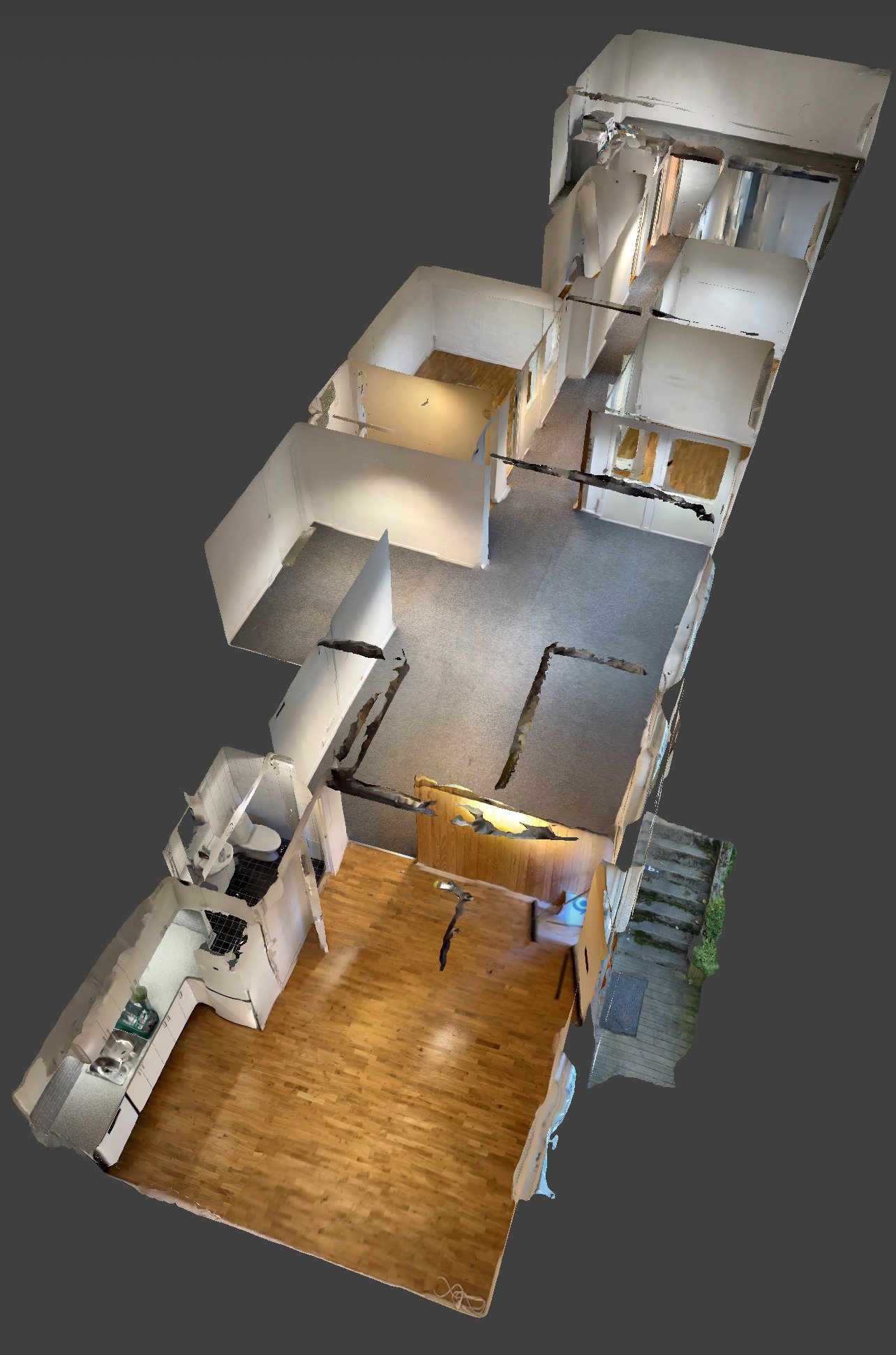
A small suggestion would be to test scanning with a phone first. You will get the feel for what you want and need from a base and entry level. The picture was scanned with an iPhone 13 Pro Max using the free app Scaniverse. The place in the picture is about 180 sqm and took about ten minutes to scan in a single session going from room to room and sniffing around like a dog. Accuracy about 1%, so you still need to cross check with real measuring. Models can be imported into VW in several formats. Phones having ladar has a definite advantage compared to photogrammetry as it's much faster. On the Apple side it means iPhone 12 Pro models or later, and later iPad models (check before buying). You can scan with Android devices too, but my knowledge is limited there, so ask around.

-
Sketchup download taking hours, how do I cancel it?
Claes Lundstrom replied to MGuilfoile's question in Troubleshooting
They have indeed shaped up a lot. It was a complete mess. Apple invested a man-year in it just to optimize Blender on the Apple side, so it's quite fast as well. Still, after watching some tutorials, and played with it a fair amount of time, I still feel the user interface is still a bit of a mess. My point is, when looking back at my work back to 1985, I have always preferred apps with a clean user interface. I tried several CAD apps back then and ended up with MiniCAD 2, not because it was the fastest (it wasn't) or the most advanced (it wasn't), but because it was easy going and straight forward, and it had rudimentary 3D. Since then, I tried many CAD apps. Some where more advanced, but often fell through due to a bad interface. FormZ was such an example. The same apples with rendering apps, och which I have probably used at least ten over the years. Again, best user interface always generated shifting to a new app, not most advanced. As an app developer, my favorite key word has always been "modeless", essentially meaning finding an absolute minimum number of steps required to get something done. A friend illustrated it well when he did a shift from one app to another. He did a certain task in his favorite app, which took about two hours. He then tried it in another app, concluding that it took seven minutes. Time is money! -
Sketchup download taking hours, how do I cancel it?
Claes Lundstrom replied to MGuilfoile's question in Troubleshooting
The booleans in my mesh examples are open shapes (so they do leak), and they still always work as solids. OK, my imported meshes never leaks, so I guess it can be problem for messy meshes. Leaks is a problem with shapes intended to be closed, where there is a need for volume and center of mass calculations. Incorrectly facing normals can also be a problem here. -
Sketchup download taking hours, how do I cancel it?
Claes Lundstrom replied to MGuilfoile's question in Troubleshooting
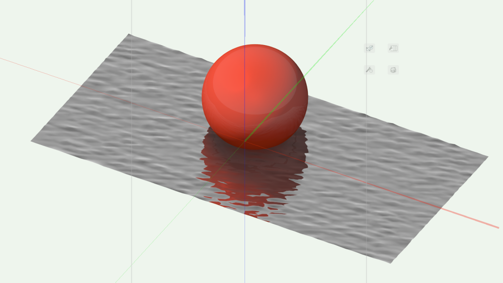
Meshes may not technically be defined as solids, but in reality, they are for sure solids too in the sense that they work and operate as solids. You can add and subtract solids to it, and on closed shapes, you can calculate volumes etc, on them. It usually work very well on the meshes I import, and I typically do 90% of my mesh modeling externally. The example show an imported mesh surface, where I did both solid subtractions and additions without any problem.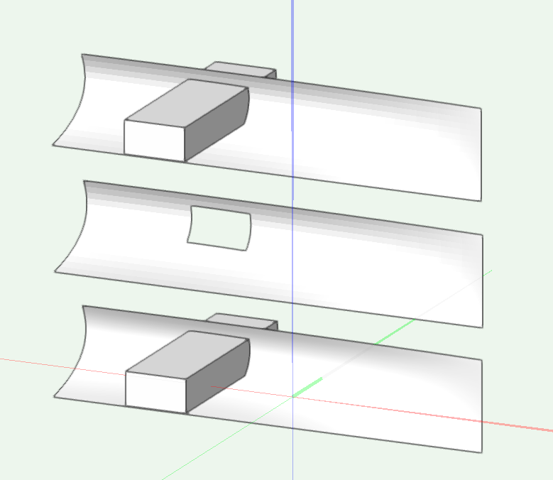
-
Affinity still has some catch ut to do in some areas. Been using Photoshop AI quite a lot lately for generating backgrounds, and that is an area where Affinity needs to step up. The spelling checkers also needs a major update for those of us not speaking one of the bigger languages. You can fix it, but it's primitive at best. I never liked Adobe Illustrator much, and therefore used Freehand quite a lot back in the late eighties and early nineties, when the rendering apps at the time where pretty much unusable. Now that Affinity Designer got DXF/DWG in/out that works much better than the notoriously unreliable equivalent in Illustrator, and importing PDF from VW works well, I have moved 100% to Affinity Designer. Being able to export SVG is also useful, since VW does not do this for some reason. All in all though, I really like the Affinity line, and use it quite a lot as a supporting unit in my workflow. They have evolved a lot in a short period of time, so most likely, they will have an impact as they close up on Adobe.
-
Renderworks textures for water surface
Claes Lundstrom replied to Helen Palmer's topic in Site Design
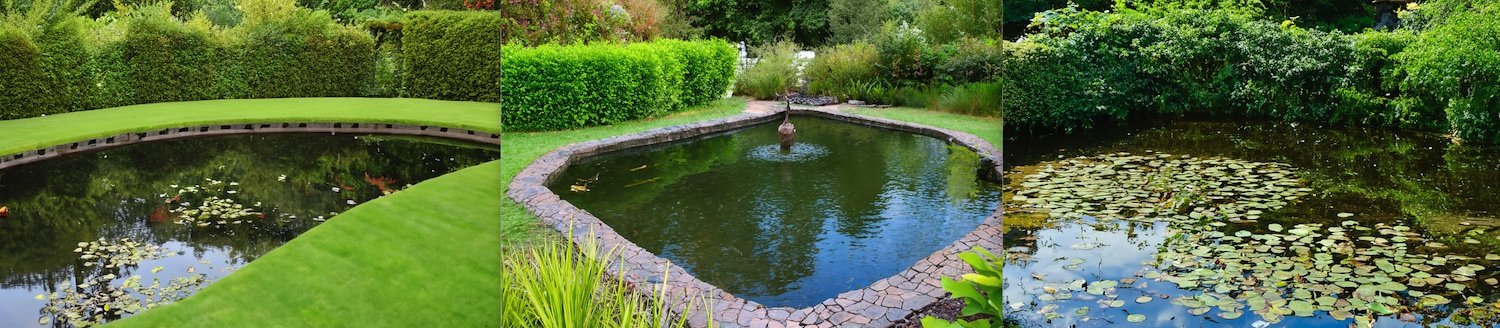
I totally agree with Peter here, backgrounds are absolutely essential for most renderings, and especially for water. An important thing to know is also to consider the direction of the light. Lights behind the viewer tends to make water look gray and plain whereas the opposite makes it come alive making it shine and sparkle. The opposite of course applies for the object you visualize, so the trick is to find the sweet spot between those factors. Here are a couple of examples showing the impact of the background, where they very much set the mood for the entire picture on some more open water renderings.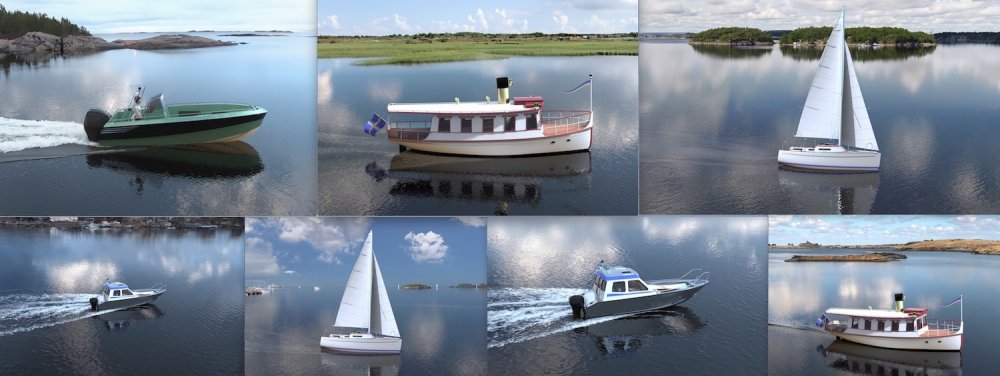
-
Renderworks textures for water surface
Claes Lundstrom replied to Helen Palmer's topic in Site Design
A good water texture is very shiny and reflective, has a bump map for waves, and that's it. It really doesn't have a color, as the color is always and almost a 100% reflections of the surroundings. I generated these three images in Photoshop AI as examples, and if you study the colors of the water surface, you will see that it all consist of reflections. It can be more or less blurred dies to wind and waves, but it's never the less reflections. The only exception is when the water is very clear so that you can see the bottom.
-
The problem is in the receiving app, not in Vectorworks, as well as in other app I tried. If I import a file into Apple's USDZ viewers, it will come in being in scale, unless it's too big to fit into a technical boundary box that many of these apps have. If I import a say 50 meter object, it will scan down of crop the model. It you import a typical car, it will work. On the Adobe Areo side, it does not import in scale. You have to wing it, and if it goes beyond the box, it will start to crop the model.
-
AI Visualizations-Thougthful discussions
Claes Lundstrom replied to Luis M Ruiz's topic in AI Visualizer
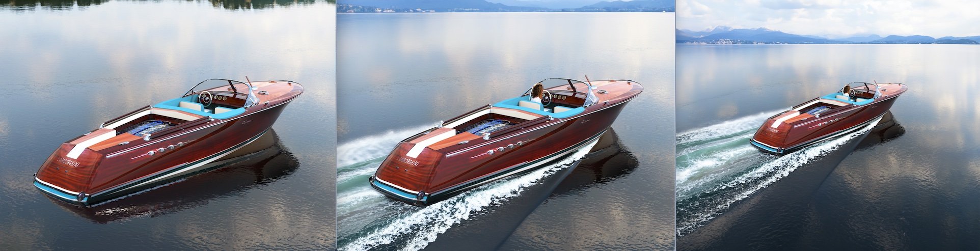
It's based on a 1968 Riva Aquarama, specifically based on Lamborghini founder Ferruccio Lamborghini's private Riva powered by twin Lamborghini V12 engines. The textures are UV-mapped from a series of pictures of the real boat. Here is a link for those interested; On product renderings of boats, you typically use comparatively flat water as too much drama on the surrounding tends to distract more than it adds to the picture. I guess the message is that it's something pleasant, not something dangerous. -
AI Visualizations-Thougthful discussions
Claes Lundstrom replied to Luis M Ruiz's topic in AI Visualizer
On the subject of AI, I played around a bit with AI in Photoshop. Generating full images generates very mixed results. Some ok, some terrible. It does however better when adding elements to the picture, and for extending a picture beyond the borders of the picture. In this example, I started with the rendering to the left, added some motion waves about the boat and a coast line far behind. In the right image, I extended the image on all sides to get more of an overview. The waves probably took 5-10 attempts to get the effect I wanted (Photoshop generates suggestion in batches of three). The coast line was ok within one try. The same applied to the extensions, though Photoshop seems to prefer extending in one direction at the time.
-
This is a really really basic mapping that should just work if you ask me. I work with UV-mapping on a daily basis. It's an absolute must to have something that is easy to use, delivers perfect high quality results every time, with a minimum of fuss. Perhaps the developer team needs to sit down and do a proper update on these features.

-
Which app do you use ? On a basic level, Apple's USDZ viewers in the iPhone/iPad and Mac Preview gets it right in scale every time, if you set the drawing units right, so it can't be that it doesn't work in principle. Adobe Aero does not, you have to set it up manually. So, there must be something else messing it up.
-
Yes the bottom picture looks reasonable right, though it was a bit too low res, so I pumped it up with AI. Globe.vwx
-
Water.vwx