Conrad Preen
-
Posts
1,023 -
Joined
-
Last visited
Content Type
Profiles
Forums
Events
Articles
Marionette
Store
Everything posted by Conrad Preen
-
Thanks guys! This kind of input helps a lot. Let me read back to you what I understand to check that I've got it. What we are after is a generalized cabinet that you can define the look of. And that Equipment Items will detect and update their locations accordingly. Essentially behaving a bit like a Room but with nice graphics. How am I doing? Conrad
-
@JonnyAVC Thanks! Yes we will be adding those back in by popular demand. Conrad
-
Overall scale issue after upgrading from 2020 to 2021
Conrad Preen replied to sbecraft's topic in ConnectCAD
@Ljones Thanks, yes we are aware of the problem and we are looking into it. Conrad -
I guess you could do the schematic as an abbreviated version like Speaker 1 ... 100. You know dotted lines. What you really need is to put Equipment Items on floor and reflected ceiling plans. So you could create a symbol that looks like your speaker. Create an Equipment Item and then select Use Symbol in the Object Info Palette and select your speaker symbol. That gets you and Equipment Item that looks like your speaker. Duplicate this and rename it to create all your speakers and place them on the plans. Use Create Report menu to get a report of Equipment Items. Just my 2c worth Conrad
- 2 replies
-
- 1
-

-
- loudspeakers
- connectcad
- (and 2 more)
-
@joneztria That sounds like an option we could easily re-instate... I'll give it a look now. Thanks for letting me know! Conrad
-
@Kelzilla1000 Interesting... I hadn't thought of that .
-
ConnectCAD Sockets paste in place far from device
Conrad Preen replied to TLeatherman's topic in ConnectCAD
@TLeatherman Hello, That looks related to another copy-paste issue we saw. It is fixed in the next service pack. Thanks for the report Conrad -
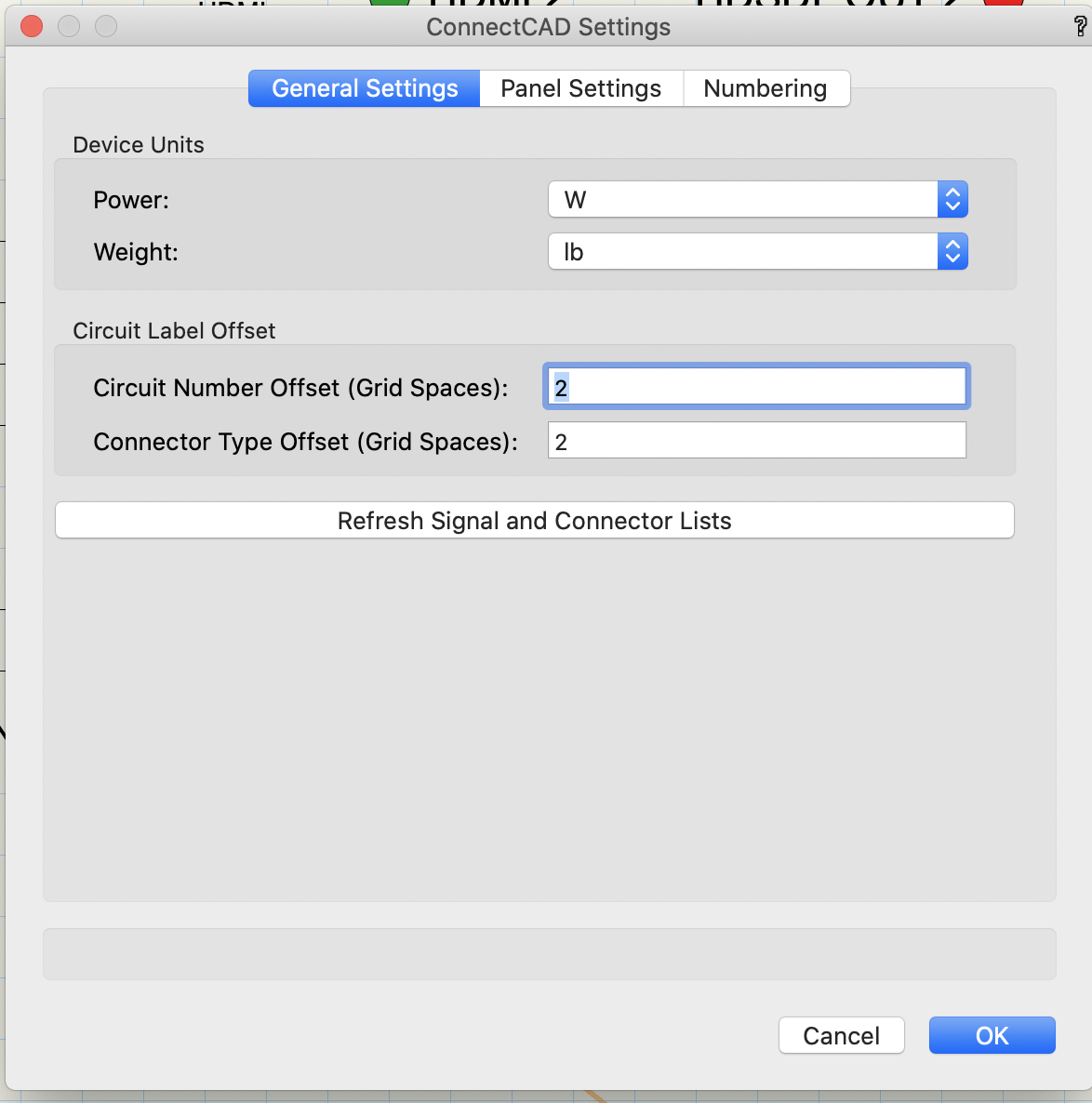
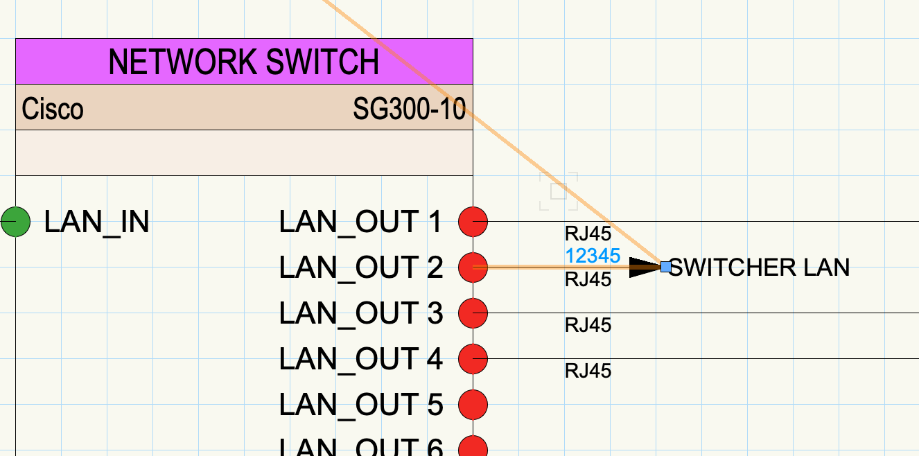
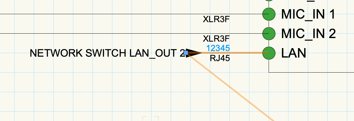
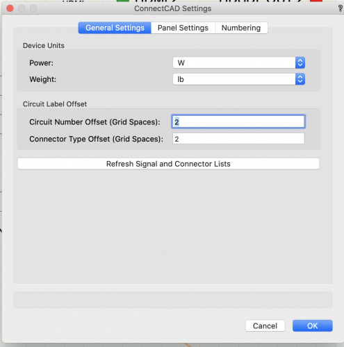
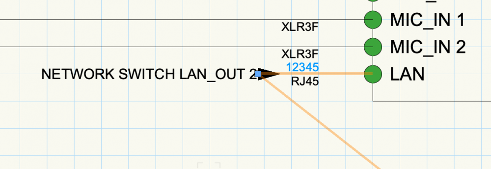
Hi @mark4 These screen shots are from your file showing the settings I've used and the results. All I did was to change the Circuit and Connector Type Offsets. To me these look eminently satisfactory. What seems to you to be wrong with this? You know Mark, we have known each other as developer and customer for years now and we have met online on several occasions. And I think you will agree that I have addressed every issue you have raised with me. So can I ask you kindly to avoid remarks like "less than professional", these do not really help our communications. They simply leave myself and my team feeling less motivated to assist you. Conrad

-
Just to fill you in, nowadays the circuit path only has arc vertices in it if there's a hopover. Otherwise all circuit paths have corner vertices, and the object draws the vertices rounded or chamfered according to the style selected in the Object Info Palette. Hopovers get deleted if you move a device. Not really a big deal. If you need a lot of hopovers usually that means that the schematic could be better structured. Conrad
-
Hi Matt The word from Niko is that if you move your devices a bit this will go away. We had to change the way we implemented hop-overs since 2016. We will also do a real fix in a coming release. Thanks for reporting! Conrad
-
@TomWhiteLight great idea ! will you file the enhancement? Conrad
-
@livespace josha The software currently uses a default of 6 snap grid spaces as the standard width but this automatically expands if the socket names are too long. In earlier versions the width was controlled by a tool preferences and there was no auto-sizing. We will be re-instating the default minimum width together with auto-sizing. Generally we try to keep the number of tweaks to a minimum because these can be really hard for new users to navigate. Conrad
-
@Nikolay Zhelyazkov good to know! But rotating sockets still isn't "as-designed", otherwise we could do away with orientation altogether. Hmmm! Could be an idea? 😄 C
-
Never mind I added it to the wish list. C
-
It's a bit hard to read...
-
Y e s T h o m a s we didn't anticipate v e r t i c a l E x t e r n a l s Conrad
-
Ok, these are things for us to think about... But just to manage expectations a bit - there is always a risk of unexpected results when you start using things in ways they weren't designed for. If it works that's great but if it doesn't then that's not necessarily wrong either. The bottom line here is that you want the option for text to run vertically in these cases so as to achieve a closer socket spacing. That's what I take away from this discussion as an improvement to be considered. Conrad
-
Hey Matt, ConnectCAD has been steadily improving over the years !!! All signal type coloring is now done using Vectorworks Classes. so for each signal type a class is created named Sys-Circuits-<sigtype>. You can edit all the attributes applied to your signal type by editing the class attributes. So "R G B LS LW " are no longer relevant because the class takes care of all that - much better. I'm pretty sure this is covered in the online help too. Our Tech Pubs team do a great job. But, if there is something missing please do let me know. Conrad
-
Ah now I get it. I'll add this point to my notes. Good that you have a workaround though because I think we have more than enough already in terms of new stuff to test. Conrad
-
@Thomas Peters Thanks for the feedback. "Let them eat cake" is our slogan. Seriously though I definitely keep that in mind. Conrad
-
Hi, Sockets are spaced on multiples of the snap grid setting. The horizontal spacing is greater because you mostly need room for the socket name to be displayed. This is an exercise is pleasing most of the people most of the time. Conrad
-
Request: Specifying the "Rack Elevation" Layer
Conrad Preen replied to Thomas Peters's topic in ConnectCAD
It would be great if you could just create your equipment items on any layer you like... We have already thought about it 😁 coming soon 😉 Conrad- 1 reply
-
- 2
-
-
WOW !!! This is way off-topic !!! But no worries everyone starts somewhere 🙂 C
-
Thanks Jens Believe me I would be happy to extend the customisation capabilities of sockets, but I don't want to lead you to places that in the future may not be supported. So please bear with me on this. Regarding device labels check this thread Best Conrad
-
Hi Jens, Would it work for now to customise one of the existing socket symbol types in a template? Conrad