Conrad Preen
-
Posts
1,023 -
Joined
-
Last visited
Content Type
Profiles
Forums
Events
Articles
Marionette
Store
Everything posted by Conrad Preen
-
Disable Automatic Cable Type Based on Signal
Conrad Preen replied to garrettohler's topic in ConnectCAD
@garrettohler I've filed a bug for this and we will get it fixed as soon as possible. Conrad -
Disable Automatic Cable Type Based on Signal
Conrad Preen replied to garrettohler's topic in ConnectCAD
@garrettohler Thanks for reporting this - we'll look into it. Conrad -
Disable Automatic Cable Type Based on Signal
Conrad Preen replied to garrettohler's topic in ConnectCAD
@garrettohler Could you send us a Vectorworks document that shows the behavior and the steps we should take to reproduce the problem? Conrad -
Problem with "Use Symbol" for 3D rack equipment items
Conrad Preen replied to SSvectorproblems's topic in ConnectCAD
@SSvectorproblems By all means PM me the Vectorworks document and I'll take a look at it. Conrad -
Adding devices to "global" library/database
Conrad Preen replied to R_Teunissen's topic in ConnectCAD
Dear Remco, Why don't you set up a website of your own and distribute this content and whatever else the community wants to share? It would be nice to see some independent initiatives. We used to have a whole bunch of community websites around Vectorscript. It would be great to get that spirit back. ConnectCAD is part of Vectorworks now because I proved to them that it worked as an independent company. Why not do the same with content? If you believe in it go for it. Conrad- 1 reply
-
- 2
-

-
@SCOTT.T.JOHNSON Hi Scott, there is no way to do that in the Device Builder. Horizontal arrays of sockets in the general case aren't really great because their names make the spacing too great. But the beauty of ConnectCAD is that there's nothing stopping you from just creating an empty device and the adding sockets wherever you want. Conrad
-
@tk_ we are working on that too
-
@tk_ collaboration in Vectorworks where you have multiple designers working together is done through Project Sharing. There is a master file, and you can check out the layers you are working on and then save your changes back. Your lighting colleagues can do the same on their layers. That way the data doesn't have to jump between files. Check out the online help for more about Project Sharing. Conrad
-
ConnectCAD - How to create your own connector graphic styles ?
Conrad Preen replied to Enzo Vernusse's topic in ConnectCAD
@Enzo Vernusse Just posting a Google translate. Hope it does justice to your words. We will look into this. I'm pretty sure this was possible but maybe not in the way you are trying. Truth is, not a lot of people customize socket graphics. Conrad -
Problem with "Use Symbol" for 3D rack equipment items
Conrad Preen replied to SSvectorproblems's topic in ConnectCAD
Create Equipment can create equipment set to use the symbols we ship with Vectorworks if you check the box in the dialog. As Simon says CAD models from manufacturers tend to bloat your file with unnecessary detail. Thanks @Pat Stanford for explaining the symbol colors for our new users - much appreciated. C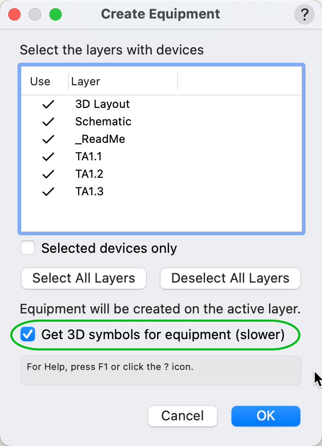
-
@wscooper Not exactly clear about your question. By "new and better connector layouts" are you talking about connector panel design? And how does that fit in with drop points that essentially are locations of equipment that has not yet been specified? Conrad
-
Using the 'category' field from the Device Builder dialog
Conrad Preen replied to Thomas Peters's topic in ConnectCAD
Yeah. The Category and Type fields in the database are not parameters of the Device. They are just there to help navigate around the database to find what you need. Noted for the future though. Conrad -
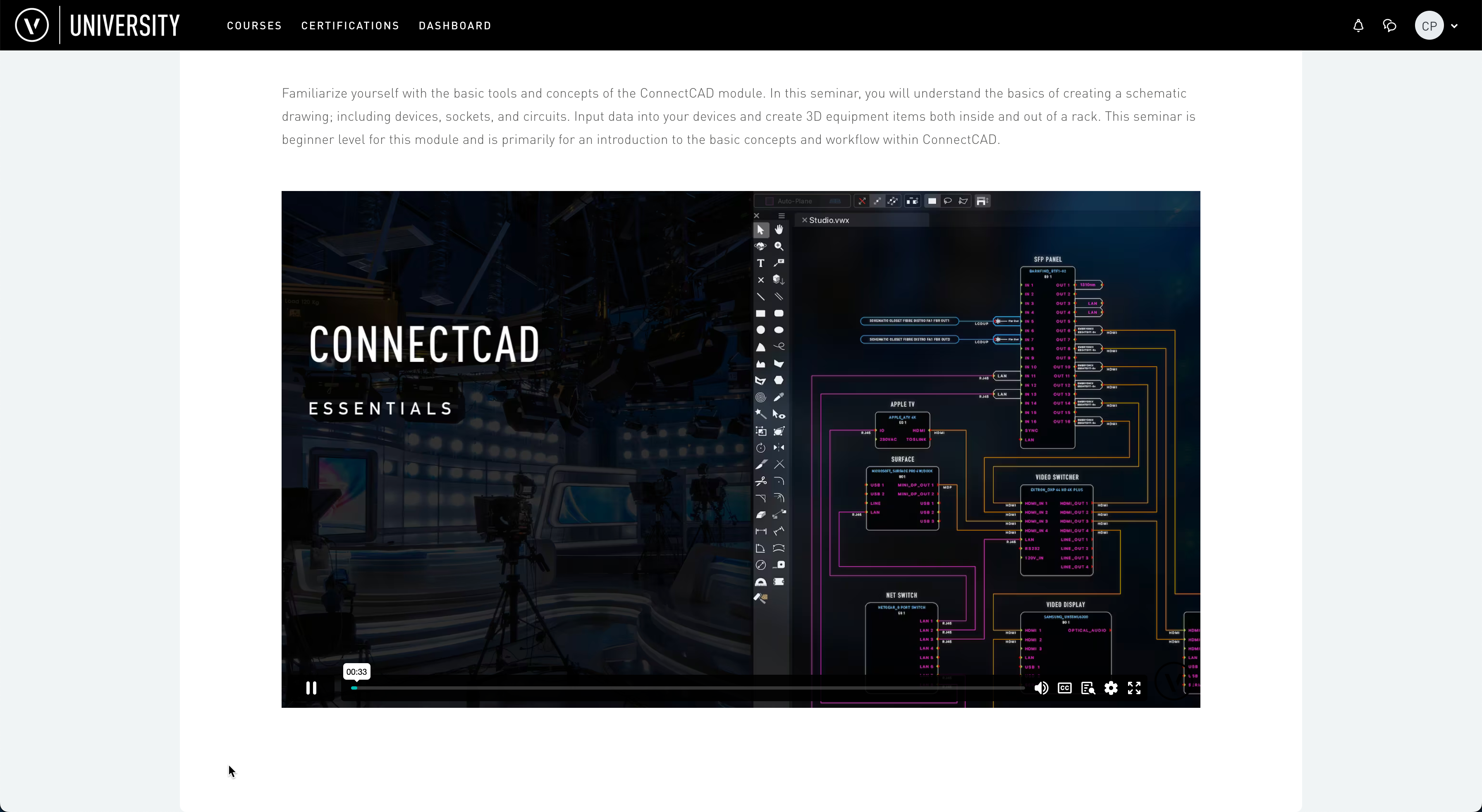
New to ConnectCAD? Check out the ConnectCAD Essentials tutorial in the Vectorworks University.

-
Worksheet Showing a Device's Active Circuits and Un-Connected Sockets?
Conrad Preen replied to btgroves's topic in ConnectCAD
@Pat Stanford There is one report that we create programmatically bypassing as you put it the normal database from criteria mechanism. This is the worksheet created by the tool Make Rack Equipment Worksheet. This list each available position in the rack as a worksheet row and what equipment if any is mounted there. Since it doesn't list drawing objects it can't use normal reporting. Thanks for your kind words - we do what we can! Conrad -
Yes, along with any equipment placed in the console bay.
-
Problem with "Use Symbol" for 3D rack equipment items
Conrad Preen replied to SSvectorproblems's topic in ConnectCAD
@SSvectorproblems Hello. Yes @spettitt is right. The purpose of the Use Symbol checkbox is to allow you to use an existing ordinary 3D symbol say one you snagged off a manufacturer's website as the graphics for your equipment item. If you have created a red symbol (convert-to-plugin-object) from your equipment item then all you need to do is drag that in from the Resource Manager directly. I will check on this problem and see if there's something we can do to alert you if you choose a red symbol. As for the socket symbol that you see that just happens to be the first in the document - we use symbols as building blocks quite a lot in ConnectCAD because it allows you to customise things. Hope this helps, Conrad -
Worksheet Showing a Device's Active Circuits and Un-Connected Sockets?
Conrad Preen replied to btgroves's topic in ConnectCAD
@btgroves I am aware that tutorial materials could be better. And that is something that I am raising with those responsible. Conrad -
Worksheet Showing a Device's Active Circuits and Un-Connected Sockets?
Conrad Preen replied to btgroves's topic in ConnectCAD
@Pat Stanford The Device Connections Report is in fact a report on the Socket objects in the drawing. But as Niko says we created specialized functions that allow you to access the parameters of the parent device of each socket. When you order the rows by Device Name you get what appears to be a database of Devices and their sockets. And of course we also have a function to get the circuits connected to each socket too! So that way we can get the cable number. Sockets also have a hidden parameter that counts the number of connections that a socket has. Basically all the parts are there and can be put together to create whatever views anyone wants. One thing I noticed in this request was that un-connected sockets are also listed. The Device Connections report will list these IF these sockets are present on the drawing. Not everyone includes all unused sockets in their devices because this eats up drawing space. Just to be aware. Conrad -
Hi @Thomas K. Have you looked at the Cable Pull Report in the ConnectCAD > Documentation menu? Maybe that's a starting point? Conrad
-
Hey everyone! If your rack names look like this when you've created a rack elevation viewport, this is why. Even though the viewport is set to Hidden Line render, objects that have no fill are rendered as wireframe because they can't hide another object seeing as they have no fill... right? So when you have Fill = None in the classes CC-Rack3D-Graphics-Top and CC-Rack3D-Text-Name the top of the rack will be see-thru meaning that you will see both the front and back labels of the rack. So to avoid this at least in the viewport class overrides give those classes a solid fill and the rear text won't show.
-
Hello @btgroves In the end this comes down to how the classes are set up. If you have Fill = None in classes CC-Rack3D-Graphics-Top and CC-Rack3D-Text-Name then these will be rendered as wireframe even though the render mode is set to hidden line. How do you hide lines when the object has no fill - right? In viewports you can override the class settings just for that viewport so you're not forced to have a fill in your model if you don't want one. I think this clears it up. The reason why it was hard for us to make it happen was that it needed 2 classes to not have fill. Best regards Conrad
-
@Nikolay Zhelyazkov Side views and trays without slots have come up before so I think we should consider these. I will create the enhancement requests now.
-
We are checking this issue and have found a reproducible test case. Once we have determined the exact cause we will get this fixed as soon as possible. Thanks for drawing our attention to this. Conrad
-
Hi Simon, Just for the others watching this thread. Putting the Rack object inside the 3D flight case symbol does not work for 2 reasons: 1. each symbol instance will have the same Rack ID, 2. the Equipment Item object/tool does not look inside symbols or groups. Given that it searches for Racks dynamically as it hovers over objects, looking inside group or symbols would probably result in an unacceptable slowdown. As things stand the Rack object and any 3D symbol representing say a flight-case have to both be top-level objects. And then everything works pretty nicely IMO. Conrad
-
Hi @CHWE Check out this thread There is a lot of explanation about adding custom text. Conrad