Daniel Dickman
-
Posts
101 -
Joined
-
Last visited


-
Can't paste cells from excel into report
Daniel Dickman replied to Daniel Dickman's topic in Entertainment
This is exactly the result I'm looking for. Can you help me understand the difference between 'Lighting Device'.'X Location' and 'Lighting Device'.'Channel'? To me these both seem to be in the Record.field format but in worksheets only the channel data can be modified. Thanks Tom. -
Can't paste cells from excel into report
Daniel Dickman replied to Daniel Dickman's topic in Entertainment
@Jeff Prince Yeah I'm trying to update the location of the objects. The copy paste workflow seems to work for some record fields but not all. For example, I can copy and paste in DMX Address or Universe information from excel into a report without issue. The ability to paste in XYZ info should be a no brainer. -
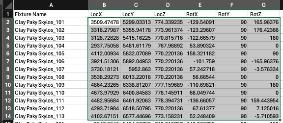
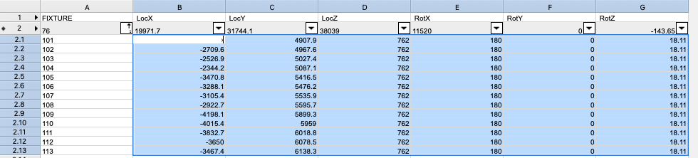
I'm working with other departments who are coordinating our 3D models and the larger project as a whole, they are working in other software. I want my VW file to align with their files. They have given me a csv file with all the XYZ locations and rotations of my fixtures (based off a laser scan/point cloud). I already roughly drafted my plot and placed fixtures. Now I want to update the XYZ position and rotations with the data my team has provided me. In my mind this should be a simple copy paste... All I want to do is copy this... and paste it here... It won't do it and I'm going crazy. This seems so simple. WHY
-
When I select an adapter, the make/model fields in the OIP are greyed out. Is there anyway to define make and model?
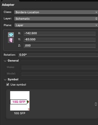
-
It also seems I cant modify pan or tilt values from a work sheet. I don't understand what the difference is modifying these values in the OIP vs a worksheet. Seems it should work in either place.
-
Hey there, I have a worksheet with a number of lighting devices and positions. Each position is exactly the same fixture layout just at different rotations. I have modified all of the Z fixture heights on one position and I was hoping to just copy paste the updated Z locations in a worksheet and paste it on to the other fixtures but it seems I can't edit any of the X,Y,Z locations via a worksheet. Anyone know why? In the worksheet I can edit channel and position name just not x,y,z locations.
-
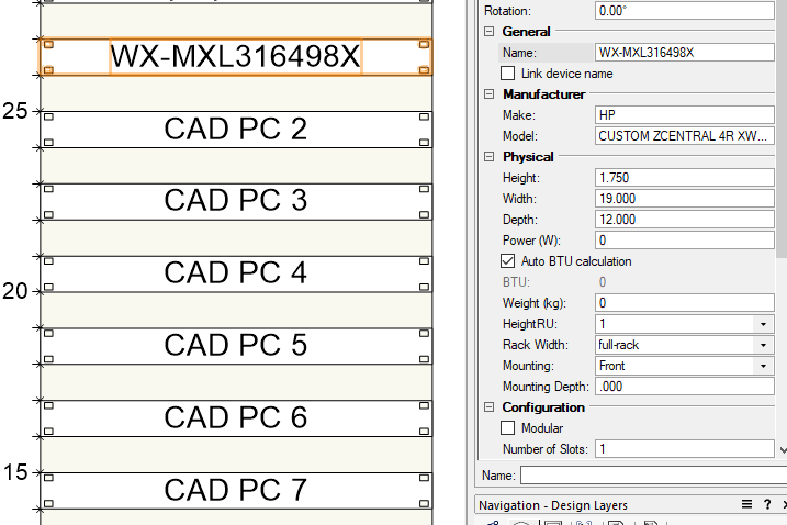
I'm working on some rack elevations, On my schematic I have some devices with the device names like "WX-MXL316498X" but the display tag is "CAD PC 1". On the rack elevation side, I frequently find myself wishing I could abbreviate an Equipment item's name similar to the Device Name/Display Tag functionality of schematic devices. If I change the name of the equipment item to "CAD PC 1" it breaks the link to the schematic device. Is there any way to display the Display Tag on an equipment item rather than the full device name?
-
Equipment Item Symbol - Not rendering in 2D Top/Plan View
Daniel Dickman replied to Daniel Dickman's topic in ConnectCAD
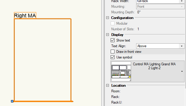
All of the low, medium, high detail levels are ticked. Interestingly, if I remove the 3D component entirely and turn it into a 2D symbol, I can get it to render correctly, but the draw in front view box must be selected. 2D Symbol - Draw in Front View Selected 2D Symbol - Without draw in front view selected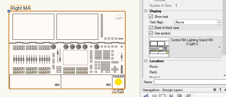
-
When using a hybrid symbol with my equipment item, I'm having an issue where the 2D component in Top/Plan view does not render correctly? What am I missing here? Equipment Item In Top/Plan View What the 2D component should look like
-
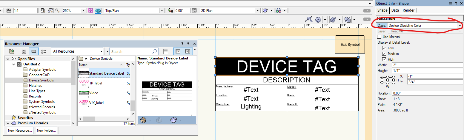
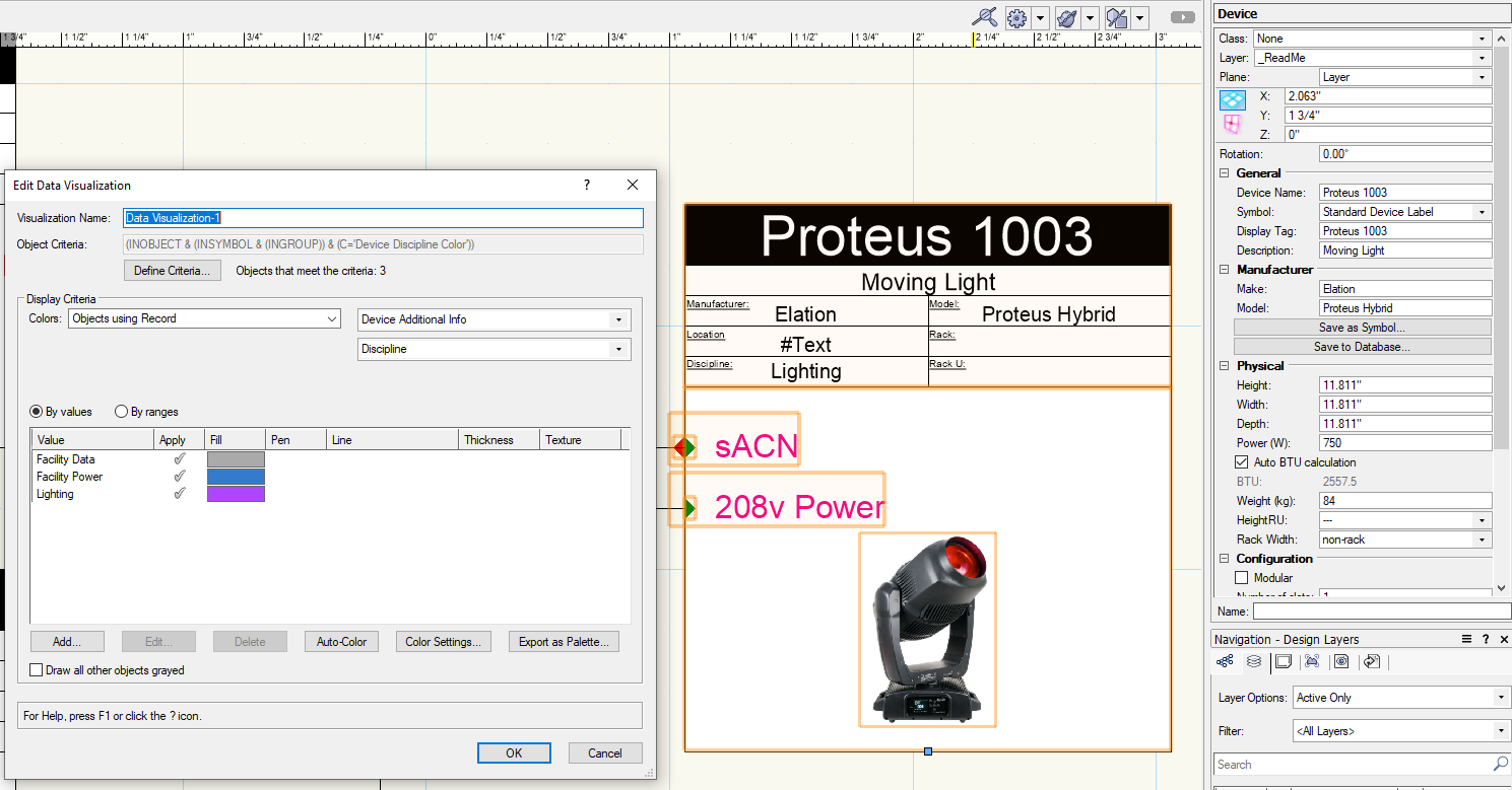
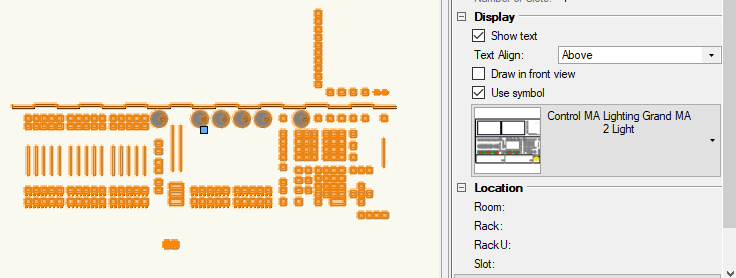
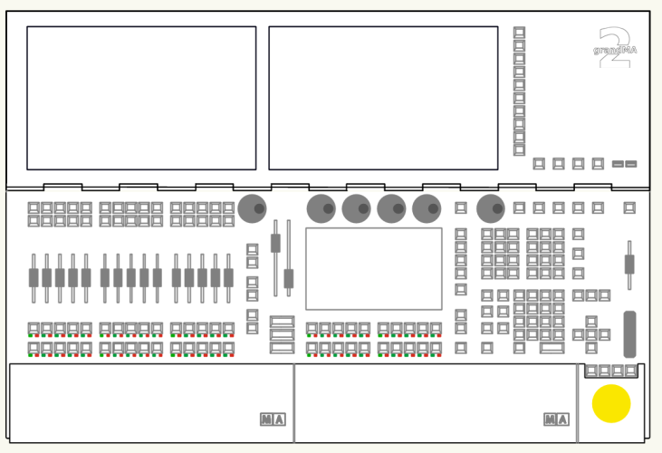
Hey all, In my drawings I like to color code my devices by discipline (lighting, audio, video, etc). Currently I'm using various device symbols that I've made for each discipline. This works good enough but Its a bit of a manual process to select the right symbol for each device. Here is what one of my typical devices looks like using the custom device symbols. In addition to this, I have a record attached to each device where I define the discipline of the device for use in worksheets. Since I'm already defining the discipline in my "Device Additional Info" record, I would like to use Data Visualizations to help color code my devices based those values. My goal is that the data visualization only changes the color of the rectangle that is behind the device tag text. I do not want the data visualization to change the fill of the entire device object. Here is what I've attempted so far... I have created a new Device symbol named "Standard Device Label". In this symbol the rectangle behind the Device Tag text is set to a fill of black and a class of "Device Discipline Color" In my new Data Visualization, I set the criteria to "Class is "Device Discipline Color" With the criteria set, it says it finds objects that meet the criteria but I can't seem to get the colors to actually change when I define the discipline field in my record. I understand that my record is attached to the device and not the rectangle inside the device symbol, so I assume that's why this doesn't work. Does anyone have ideas for a better approach?


-
Hey Conrad, I got around to testing this in the metric template and can confirm the cable tag does not overlap with the arrow. Is there way for me to manually place the cable tag on the arrow line where I want? Similar to a normal polyline circuit.
-
My company has finally upgraded to VW2023 and I'm getting around to playing with some of the new ConnectCad features. I see we can now reshape arrow circuits, but how can I move the cable tag so it doesn't overlap with the arrow?
-
Custom Params Not Updating on VWX Restart (2023)
Daniel Dickman replied to btgroves's topic in ConnectCAD
@Conrad PreenIs there any harm with us modifying the pre-made records? The record "Device Network Info Record" for example, I would like to add a field for Gateway. -
Ahhh I'm still in 2022, Our organization hasn't updated to 2023 yet. Thanks Nikolay
-
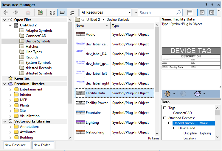
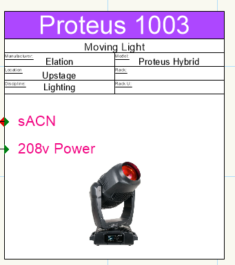
This was a very helpful video! Thanks for posting! Is there anyway we can map text inside our Device Symbol (dev_label_generic for example) to our custom records? I can't seem to get my custom device labels to display text from these records. The only way I can get text from these records to display is by adding text directly inside of the device itself (as shown in the video).