Jesse Cogswell
-
Posts
634 -
Joined
-
Last visited
Content Type
Profiles
Forums
Events
Articles
Marionette
Store
Everything posted by Jesse Cogswell
-
The Focus Point tool from the Spotlight workspace has an OIP parameter called Name that effectively replaces the Name field at the bottom of the OIP. In fact, the Name field is greyed out and disabled. Is there a way to disable that field with a Vectorscript PIO?
-
 This is intended behavior. When you open an edit container, it uses the settings of the active layer in terms of projection, view, and scale. Sheet layers can ONLY be 1:1 scale (which can screw up text size and line types when editing 2D symbols from a Sheet Layer if you tend to draft in something other than 1:1 on your design layers), and don't technically have any 3D components (can't change view or render mode). When editing a 3D or hybrid symbol from a Sheet Layer, you do have 3D view control, so it stands to reason that you should be able to also have render mode control, but that is likely why you are having the problem. A couple of "workarounds" that at least are a little more convenient: Double-click the Viewport and select Edit Design Layer and select the requisite layer. When you're done editing the texture, you can then push the Return to Viewport button to return to the Sheet Layer. I've started doing this as a way of avoiding saved views and having to toggle a bunch of visibilities. I can select a viewport that has the layers I need, then edit the Design Layer through the viewport without having to change my current Design Layer layer visibilities. You can engage the "Multiple View Panes Mode" by pressing "M" on the keyboard (unless you've changed the default). I routinely have this set to split my view in two, and it lets me edit Design Layers through the viewport while also being able to edit and see annotations simultaneously. Saves me a lot of time of jumping back and forth between a Design Layer and a viewport's annotation space. Just make sure that you have the right pane selected before pressing "M" and exiting the Multiple View Panes mode! I can't count the number of times I've opened it while editing to see a redline annotation, only to accidentally close the mode on the Sheet Layer instead of the Design Layer.
 -
For vsoInsertWidget? As far as I know, the last argument doesn't do anything. According to the documentation, it's "not implemented yet."
-
I don't have time to try this out, but I think this could be achieved by naming the locus point or the rectangle and then using a Name input node as an input for a Get 2D Center or Get 3D Info node for the locus (depending on 2D or 3D locus point) and a combination of Get Width and Get Height nodes for the rectangle. It gets tricky to have these in the object wrapper directly, as the network might not work properly if the objects were to be deleted. There could be a way to have the object wrapper be part of another Marionette network that functions as a menu command, where the Name pulls the point or width and height which gets slotted into the inputs of the object wrapper, but then get deleted. Again, I don't have time to try this out at the moment, and I am not an expert on Marionette, but I think it might be possible. Marionette is super limited when it comes to interacting with existing objects and, as far as I know, the only way to do so is with named objects.
-
Sorry, I think @Sam Jones means @jcogdell. Very similar names, but he's the VW employee that seems to have the most information about the cable tools.
-
Script to create selection scripts of used Light Instruments
Jesse Cogswell replied to Tom M.'s topic in Vectorscript
@Pat Stanford is exactly correct in terms of selecting similar plug-in types and is something I use all the time. It looks like a "Magic Wand" and can be configured to work in all kinds of ways. What you would be looking for is something like this: You can save "presets" for what you want it to do, changeable in the Mode Bar when you activate the Select Similar tool. I have one for Object Type, Symbol Name, and Class. What it won't do is select similar based on a single parameter such as fixture type. But that's easy enough to script: PROCEDURE SelectSimilarFixture; {* Selects the same fixture types as selected Lighting Device objects on the active Layer Developed by: Jesse Cogswell Date: 4/23/2023 Revisions: *} CONST kLightDevice = 'Lighting Device'; kInstType = 'Inst Type'; VAR currentLayer:STRING; check:BOOLEAN; PROCEDURE SelectSimilar(h:HANDLE); VAR testStr:STRING; BEGIN check:=TRUE; testStr:=GetRField(h,kLightDevice,kInstType); ForEachObject(SetSelect,((R IN [kLightDevice]) & (kLightDevice.kInstType = testStr))); END; BEGIN check:=FALSE; currentLayer:=GetLName(ActLayer); ForEachObject(SelectSimilar,((SEL) & (L=currentLayer) & (R IN [kLightDevice]))); IF NOT check THEN AlrtDialog('No Lighting Devices currently selected on active Layer'); END; Run(SelectSimilarFixture);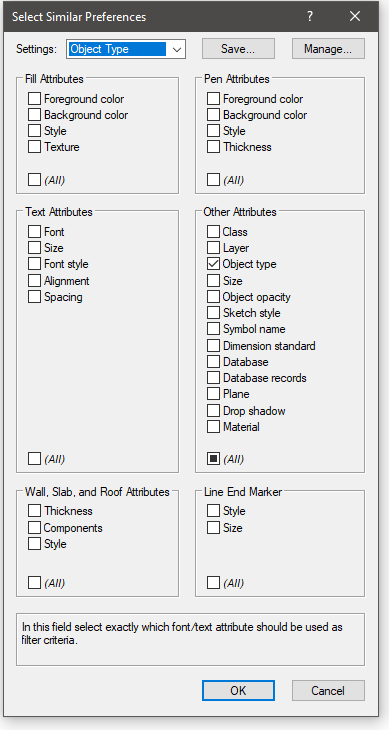
- 8 replies
-
- 2
-

-
- vectorscript
- light instrument
- (and 1 more)
-
Script to create selection scripts of used Light Instruments
Jesse Cogswell replied to Tom M.'s topic in Vectorscript
@Tom M. Unfortunately, there's not really a way for a script to write scripts directly. You could write a script that could create text files or even .vsm menu commands, but that would still involve either creating the new scripts and copying and pasting from the text files, or restarting Vectorworks and adding the new menu commands to your workspace. If you went the route of the menu commands, you would also end up with a boat-load of commands depending on how many fixture types you work with. Instead, I propose this solution: the script below will search the drawing for all Lighting Device objects and will build an array of the Inst Type fields that it finds. Then, you can select the type or types that you want to select. It's an extra click, but it's a more flexible script from drawing to drawing. PROCEDURE SelectFixtures; {* Builds an array of Lighting Device types and allows user to select all of each type in drawing Developed by: Jesse Cogswell Date: 4/24/2023 Revisions: *} CONST kLightDevice = 'Lighting Device'; kInstType = 'Inst Type'; VAR lightTypes:DYNARRAY[] OF STRING; numTypes:INTEGER; dialog,layoutDialog:LONGINT; PROCEDURE AddToArray(h:HANDLE); {Adds lighting device to array} LABEL 99; {Escape} VAR testStr:STRING; i:INTEGER; BEGIN testStr:=GetRField(h,kLightDevice,kInstType); FOR i:=1 TO numTypes DO BEGIN IF(lightTypes[i] = testStr) THEN GOTO 99; END; numTypes:=numTypes+1; ALLOCATE lightTypes[1..numTypes]; lightTypes[numTypes]:=testStr; 99: {Escape} END; FUNCTION DrawDialog(DName:STRING) : LONGINT; {Creates dialog box and returns dialog ID} CONST kWidth = 50; kHeight = 50; VAR dia:LONGINT; BEGIN dia:=CreateLayout(DName,FALSE,'OK','Cancel'); CreateListBoxN(dia,11,kWidth,kHeight,TRUE); CreateGroupBox(dia,101,'Instrument Types',TRUE); SetFirstGroupItem(dia,101,11); SetFirstLayoutItem(dia,101); DrawDialog:=dia; END; PROCEDURE DialogHandler(VAR item,data:LONGINT); {Handles dialog box} VAR i,index:INTEGER; selectInst:STRING; BEGIN CASE item OF SetupDialogC: BEGIN FOR i:=1 TO numTypes DO AddChoice(dialog,11,lightTypes[i],i-1); END; 1: {OK} BEGIN FOR i:=1 TO numTypes DO BEGIN GetSelectedChoiceInfo(dialog,11,i-1,index,selectInst); IF(index <> -1) THEN ForEachObject(SetSelect,((R IN [kLightDevice]) & (kLightDevice.kInstType = selectInst))); END; END; 2: {Cancel} BEGIN END; END; END; BEGIN numTypes:=0; DSelectObj(ALL); ForEachObject(AddToArray,(R IN [kLightDevice])); IF(numTypes>0) THEN BEGIN SortArray(lightTypes,numTypes,0); dialog:=DrawDialog('Select Lighting Fixtures'); layoutDialog:=RunLayoutDialog(dialog,DialogHandler); END ELSE AlrtDialog('No Lighting Fixtures found in drawing'); END; Run(SelectFixtures);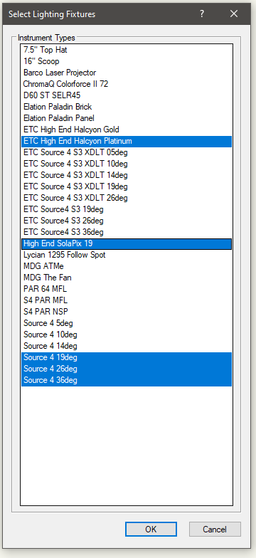
- 8 replies
-
- 1
-
-
- vectorscript
- light instrument
- (and 1 more)
-
Here's a list of all the widget types from the Developer Wiki. I have separators in all of my plug-ins that are event enabled, and have successfully been able to make them collapse. One post that might help you an awful lot is this one from _c_ (though it's in Python): They go pretty in depth about Widget Groups, which is what you are looking for. Based on the code _c_ supplies, the magic code is kWidgetGroupMode = 81 and kWidgetGroupAutomatic = 2 as constants, and the call <boolean>:=SetObjPropCharVS(kObjXPropSepcialEdit,Chr(kWidgetGroupAutomatic));, then using vsoWidgetSetIndLvl to indent one level in under the headings. I've attached an updated version of the event example I wrote for you back in January that has widget grouping written into it. Quick Edit: The attached plug-in was edited in VW2023 and is now only able to be used in VW2023 or newer. Event Enabled Example.vso
-
Get Spotlight Position Name with PIO
Jesse Cogswell replied to Steven Morgan's topic in Vectorscript
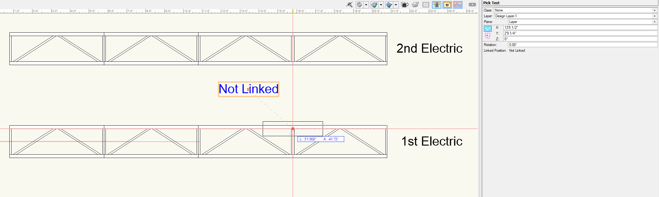
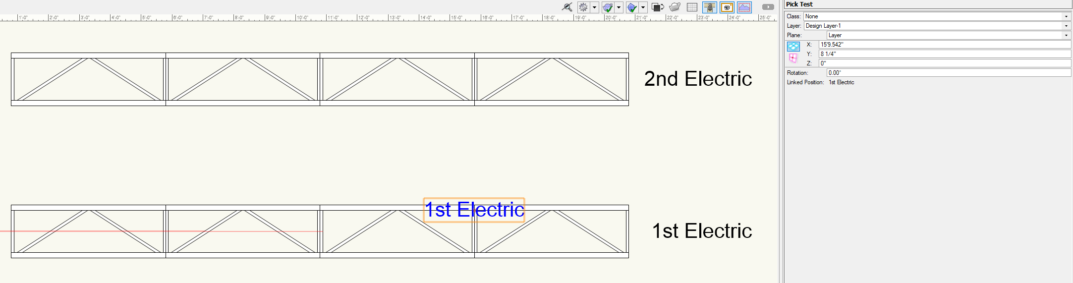
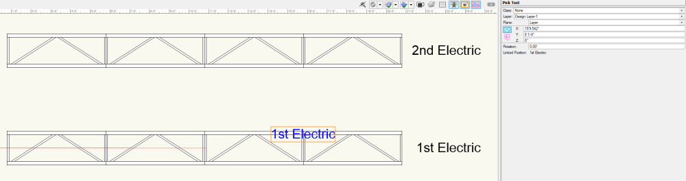
Very yes. I've attached a short PIO showing this. It's a Point Object with a single parameter, a static text parameter called linkedPos. The PIO is set to Reset on Move (this is very important). The code looks like this: PROCEDURE PickTest; VAR linkedPos,objName:STRING; objHd,recHd,wallHd,pickHd:HANDLE; origin:POINT; BEGIN linkedPos:=PlinkedPos; IF GetCustomObjectInfo(objName,objHd,recHd,wallHd) THEN GetSymLoc(objHd,origin.x,origin.y); pickHd:=PickObject(origin.x,origin.y); IF((pickHd <> NIL) & (GetName(GetRecord(pickHd,NumRecords(pickHd))) = 'Light Position Obj')) THEN BEGIN IF(GetRField(pickHd,'Light Position Obj','Position Name') <> linkedPos) THEN BEGIN linkedPos:=GetRField(pickHd,'Light Position Obj','Position Name'); SetRField(objHd,GetName(recHd),'linkedPos',linkedPos); ResetObject(objHd); END; END; Locus(0,0); CreateText(linkedPos); END; Run(PickTest); It uses GetCustomObjectInfo to get a handle to itself, then GetSymLoc to get it's insertion point. From there, it uses PickObject to get a handle to the object directly below it. It uses a quick test to see if the resulting handle is an object that exists and, using a mixture of GetName, GetRecord, and NumRecords to get the object type, if that object is a Light Position Obj (the actual definition name of the Hanging Position object). If those tests are passed, the code then checks the position's name against the linkPos parameter, if they don't match, the code uses SetRField and ResetObject to update the parameter with the new position name. Then it just creates a Locus at the insertion point and creates a text box with the position name. Pick Test Object placed between two Hanging Position objects: Pick Object dragged on top of 1st Electric Hanging Position On drag release, Pick Object pulls name of the Hanging Position and resets Pick Test.vso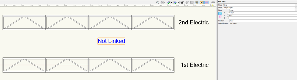

-
Is there a troubleshooting checklist for slow performance?
Jesse Cogswell replied to Ed Wachter's topic in General Discussion
No idea where it is on Mac, but on PC it is a webpage / html file found in the VWHelp directory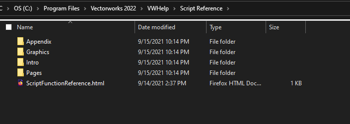
-
Is there a troubleshooting checklist for slow performance?
Jesse Cogswell replied to Ed Wachter's topic in General Discussion
@Tom W. The extra set of single quotes is what VW calls "Advice" when displaying a major alert. I know that you're interested in scripting, but I cannot stress how important the Function Reference is when doing so. If I am writing a script, even one as simple as what I posted above, I have this open on another display. I've been writing scripts in VW for 12 years and still refer to it constantly. Personally, I prefer the offline reference found in the VWHelp directory in the application folder, but both the offline or online (linked above) are incredibly valuable tools.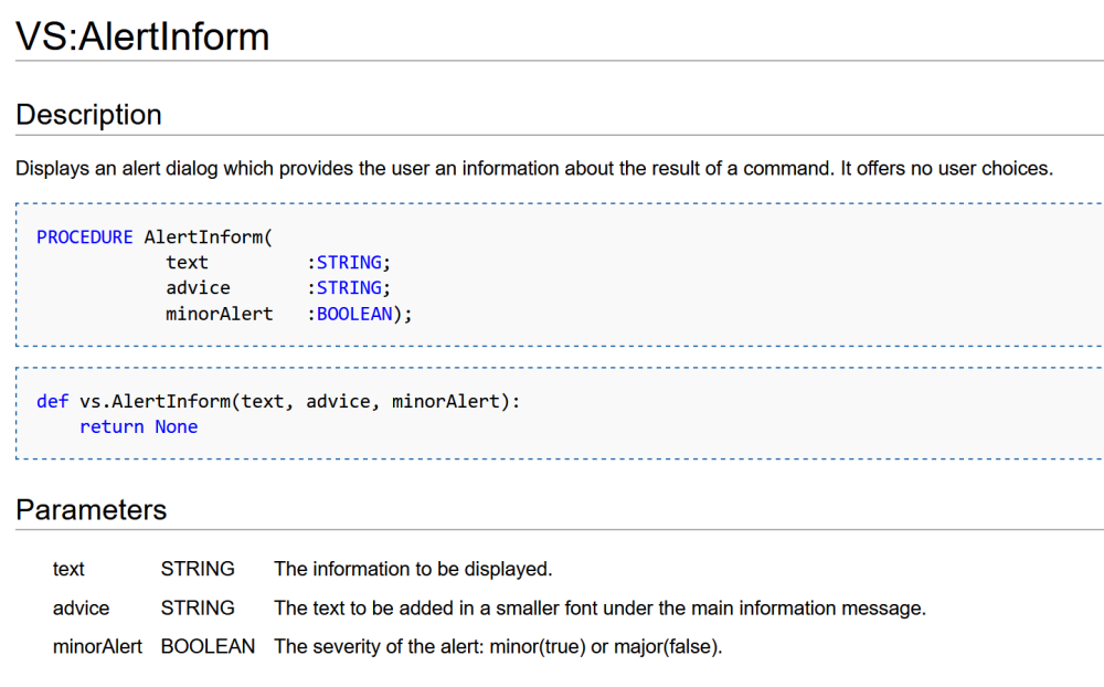

-
Is there a troubleshooting checklist for slow performance?
Jesse Cogswell replied to Ed Wachter's topic in General Discussion
@Tom W. What do you want the minor alert to say? To add a minor alert saying "All object history has been cleared", the code would look like this using the AlertInform procedure: PROCEDURE ConvertAllToGenSolid; {* Converts all Solid Addition, Solid Subtraction, Fillet, and Chamfer objects into Generic Solids *} PROCEDURE ConvertSolid(h:HANDLE); VAR solidHd:HANDLE; BEGIN solidHd:=CnvrtToGenericSolid(h); END; BEGIN IF(YNDialog('This removes all solid modelling history in drawing and cannot be undone. Continue?')) THEN ForEachObject(ConvertSolid,(INSYMBOL & (T=SOLIDCSG))); AlertInform('All object history has been cleared','',TRUE); END; Run(ConvertAllToGenSolid); -
Is there a troubleshooting checklist for slow performance?
Jesse Cogswell replied to Ed Wachter's topic in General Discussion
@Tom W. Unfortunately, because the CnvrtToGenericSolid function returns a handle, it requires being given its own procedure since ForEachObject ONLY works with a procedure taking a single handle argument, so CnvrtToGenericSolid being a function returning a handle doesn't work. If CnvrtToGenericSolid didn't need have the return value, the script could be a single line: ForEachObject(CnvrtToGenericSolid,(INSYMBOL & (T=SOLIDCSG))); -
Is there a troubleshooting checklist for slow performance?
Jesse Cogswell replied to Ed Wachter's topic in General Discussion
One of the biggest hits in performance that I've seen is caused by objects modelling history. If your file is running slowly and has 3D objects in it, it would be the first place to look. Any time you do a Model - Add Solid or Model - Subtract Solid (referred to in modeling as a "boolean operation"), it is saved in that object's history so that you can you can edit the object later. Where this gets dicey is if you have objects that have many nested steps (solid addition inside a solid addition inside a solid addition inside a solid subtraction, etc), as each step will take a hit on both performance and file size, and if you have a lot of objects in the drawing built this way, it quickly adds up. One major culprit is through using the Push / Pull tool when modeling. You have to be really careful which mode of the tool you are in. If you are in Extract Face, every time you use the tool on an existing solid, it adds a step to the object history. So if you are free-form modeling an object as you would in something like SketchUp, you might end up with an object made up of a couple dozen Solid Additions / Subtractions. There are a couple of ways to combat this. Personally, I don't use the Push / Pull tool at all and prefer to do all of my modelling manually by editing extrudes and sweeps and by consolidating multiple boolean operations into a single Model - Add / Subtract Solid command to make sure my object history is as concise as possible, ideally no more than three or four steps depending on the complexity of the object. My ultimate recommendation is to, once modelling is complete, is to select the final Solid Addition / Solid Subtraction object and use Modify - Convert - Convert to Generic Solids. This will eliminate the object history. So, no more editing, but it frees up a lot of performance and file size. A user of this forum who was new to Vectorworks and having come from SketchUp had designed a computer case with multiple vents, screw holes, and other openings, all modeled using the Push / Pull tool. Even though the drawing only consisted of a single object, due to the complexity of that object's history, the file size was literally 3GB and it ran like a slide show. Simply selecting the object and running the Convert to Generic Solids command brought the file size down to 1MB and ran buttery smooth. However, going through a file and identifying the culprit objects can take a huge amount of time, so here's a short script that will convert ALL solids into Generic Solids with no history. MAJOR CAUTION: do this only when you are sure you want to remove object history, it cannot be undone. Use at your own risk. That being said, if you make sure to run a save and run the script, if the drawing performance improves than it means that an object is definitely causing you grief. You can reload the drawing and then try to hunt for the offending object. PROCEDURE ConvertAllToGenSolid; {* Converts all Solid Addition, Solid Subtraction, Fillet, and Chamfer objects into Generic Solids *} PROCEDURE ConvertSolid(h:HANDLE); VAR solidHd:HANDLE; BEGIN solidHd:=CnvrtToGenericSolid(h); END; BEGIN IF(YNDialog('This removes all solid modelling history in drawing and cannot be undone. Continue?')) THEN ForEachObject(ConvertSolid,(INSYMBOL & (T=SOLIDCSG))); END; Run(ConvertAllToGenSolid); It's also important to be smart about how your solids are constructed. If you want to model a cube with a hole going all the way through on the vertical axis, it's far better to use Clip Surface to put the hole in the rectangle making up your cube extrude than it is to do a boolean operation with a cube and a cylinder. I should also say that VW gets really grumpy when you create an extrude or sweep that is made up of more than one object. It will totally let you do it, but your performance will take a significant hit depending on how many objects are in the extrude / sweep and how many of those extrudes are in the drawing. The best way to fix this after the fact is to edit the sweep and select all components and use the Modify - Compose command to create a single polyline, or for an extrude made up of multiple objects, select the extrude and use Modify - Ungroup, this will break the extrude out into multiple extrudes. -
the selected object has no edit behavior
Jesse Cogswell replied to Mdixon3's question in Troubleshooting
Double-click behavior is something defined within the code of the plug-in itself and is not consistent across Vectorworks (Lighting Devices launch the same dialog as the Edit button from the OIP, Title Block Borders launch a dialog allowing you to edit the layout, project data, or sheet data, Instrument Summaries launch the Build Summary dialog, etc). You are getting the warning because the Video Screen object does not have anything defined as double-click behavior. As far as I can tell, the Video Screen object has never had double-click edit behavior, as I've tested it going back to VW2019 and receive the same message. I can't speak to the Landru Design version of the tool, but the one that comes with VW has never had double-click edit behavior. -
"Show other objects" shortcut
Jesse Cogswell replied to Brandon Wardell's topic in General Discussion
Almost exactly the same: vs.SetPref(14, not vs.GetPref(14)) -
"Show other objects" shortcut
Jesse Cogswell replied to Brandon Wardell's topic in General Discussion
Super-duper simple. Script is a single Vectorscript line: SetPref(14, NOT GetPref(14)); -
Spotlight: Insert a lighting device
Jesse Cogswell replied to kevin.hayward's topic in Python Scripting
There was a change made to the Lighting Device object in VW2021 that necessitates an additional field for setting the symbol, "Symbol Definition". What your code is missing is: vs.SetRField( hNew, 'Lighting Device', 'Symbol Definition', symbolName) You now need this in addition to the Symbol Name field. As for the data, you are using the ApplyLightInfoRecord procedure correctly, so I'm not sure if it's tied to the same problem or if there is a bug with the Python implementation of ApplyLightInfoRecord. This should apply the data found in the Light Info Record attached to the passed symbol to the Lighting Device object (I can surely say that it works in Vectorworks scripts that use it). If the data isn't coming through, verify that the Light Info Record is indeed attached to the symbol and has the correct information. For your luminaire list, your snippet with vs.BuildResourceList is a good start, but it's going to include every symbol found in the drawing to your list regardless of whether the symbol has a Light Info Record record format attached. In my scripts that need a list of fixtures found in the current drawing, I start with the BuildResourceList but then comb through that list and create an array of symbol definitions that have the Light Info Record attached. Keep in mind that this does require a nested loop to scan each attached record format, as lighting fixtures commonly have more than one attached. Here's a function that I have in one of my scripts that does this. It's in Vectorscript, but you should be able to get the idea. It scans the given symbol and if it finds a Light Info Record, it adds the symbol name to the global array fixtureDefs (Vectorscript does not allow you to return dynamic arrays in a function). FUNCTION GetFixtureDefinitions : INTEGER; {Builds array of fixture definitions and returns number of definitions} CONST kSymbol = 16; VAR i,j,counter:INTEGER; resList,numItems:LONGINT; symDef:HANDLE; recordCheck:BOOLEAN; symName:STRING; BEGIN counter:=0; resList:=BuildResourceList(kSymbol,0,'',numItems); FOR i:=1 TO numItems DO BEGIN symDef:=GetResourceFromList(resList,i); recordCheck:=FALSE; FOR j:=1 TO NumRecords(symDef) DO IF(GetName(GetRecord(symDef,j)) = 'Light Info Record') THEN recordCheck:=TRUE; IF(recordCheck) THEN BEGIN counter:=counter+1; symName:=GetNameFromResourceList(resList,i); ALLOCATE fixtureDefs[1..counter]; fixtureDefs[counter]:=symName; END; END; GetFixtureDefinitions:=counter; END; -
MVR exports into external 3D pre-vis software
Jesse Cogswell replied to Nathan1fb's topic in Vision and Previsualization
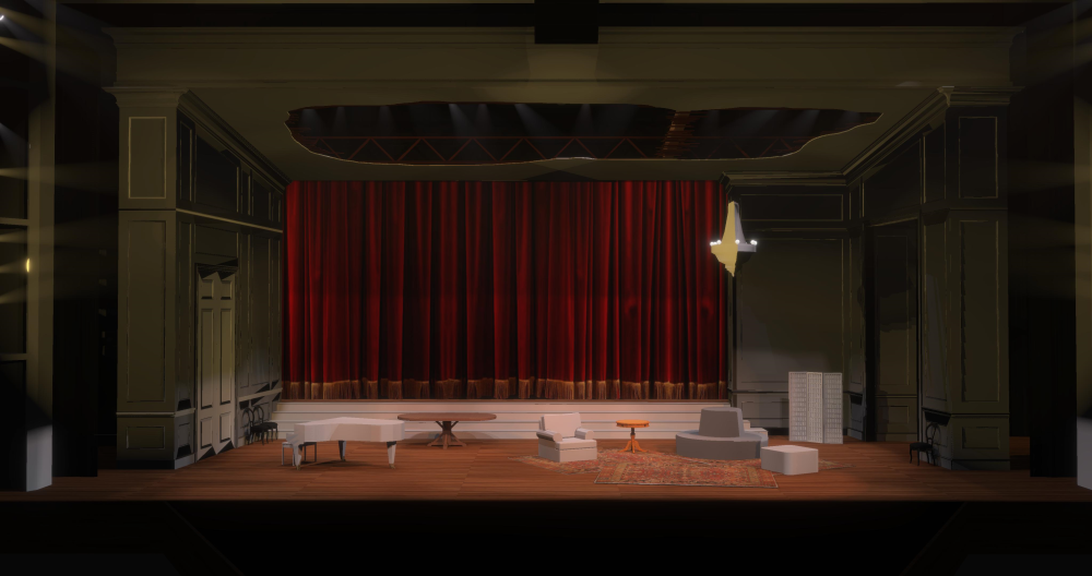
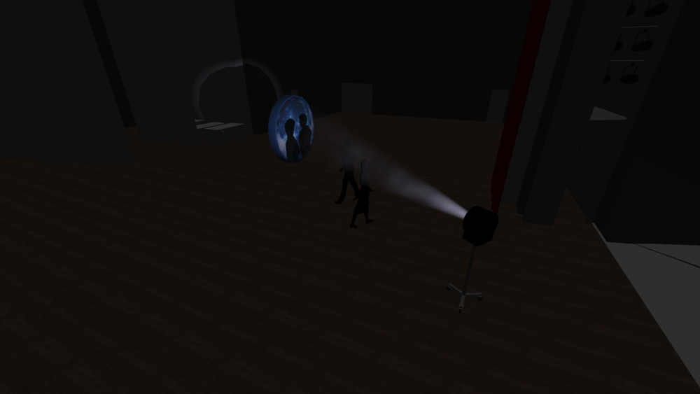
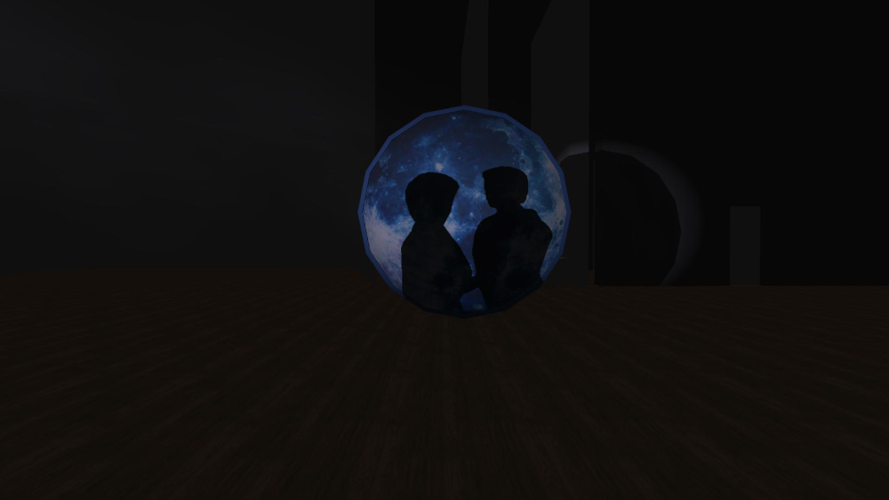
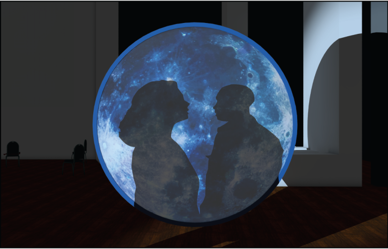
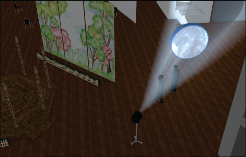
I bought Vision in 2017 shortly after they were officially acquired by Vectorworks specifically to help pre-cue a production of In the Heights that had a relatively short tech period. I went with Vision at the time because of the relative ease of getting a model out of Vectorworks and into a pre-vis software without having to build everything twice. The plot had relatively few moving lights (18 total, a mixture of VL 3500s, SolaFrame 1500s, and SolaWash 2000s) and a lot of conventionals (380). Unfortunately, there were several bugs with the fixture profiles for the SolaFrames and SolaWashes (SolaFrames had a bug with the color wheel where it constantly jump between two colors unless you put the wheel in Continuous Spin mode, SolaWashes had the iris inverted and didn't cast shadows), and the file ran really slow when running cues because of the sheer number of fixtures. Vision's speed very much hinges on the number of emitters and whether they cast shadows. Rocking a plot with 300+ emitters, all casting shadows (very important for theatre), meant that watching crossfades between cues turned into a slideshow. So, I was not able to use pre-vis for the intended purpose of pre-cueing the show, but I did find that it was fantastic for setting focus points. That production did a two weekend run-out to another venue with no additional tech time outside of a single run-through rehearsal. I very purposefully made my plot 1:1 for both venues, and built all of the moving light presets out focus palettes that matched my conventional acting areas. Between venues, I removed fixtures from palettes that they didn't need for the show, so when we hit the second venue, I just had to update the palettes and the show was 97% of the way there. Moving light focus took all of 20 minutes. But being able to build those focus palettes at home and correct things like flip direction saved an IMMENSE amount of focus and tech time. Moving forward, I've used Vision a lot for building palettes and base presets before tech and much less often for pre-cueing. I've pre-cued small theatre shows with low fixture counts, but recently run into problems with how Vision renders color temperature, making a N/C Source 4 look like it has R09 dropped in it. This necessitates manually adjusting the color temperature of every Source 4 in the plot and bumping it up 1800K just to get "realistic" color output. The other thing to keep in mind is that things like lens focus will NEVER be accurate. I'm not sure if this is something that has been solved in Capture, L8, or Depence, but in Vision, if the Edge parameter is at 50%, the edge will be sharp regardless of which gobo wheel is on, or the iris is in, or the shutters are in. In real life, these all occupy a different part of the focus train in terms of sharpness. This means that you can't really do things like layering gobos or animation in Vision and have a realistic sense of what it will look like. Things like gobo size and shutter placement are also not entirely accurate to "real life" and will always take some adjustment. One thing that pre-vis is super great for is music and event shows using beams as "eye candy." Vision encourages turning off the Cast Shadows option for the sake of performance and framerate, which is a difficult ask for theatre work but easy if you're only worried about building patterns with beams. I don't do a lot of that kind of work, but during the pandemic I spent some time timecoding moving light shows to music and can absolutely see the value in pre-vis for that purpose. Since coming back from the pandemic, I went back to lighting and programming primarily theatre, dance, and opera. With the advent of Eos 3.0 and Augment3d, where the lighting console now knows where the lights are in space, I don't think I've opened Vision more than updating it to the newest service pack. For a big musical with 70+ movers and 60 focus points, I can now use the console to rough in my focus points in 20 minutes by putting in XYZ values instead of taking a week manually focusing in pre-vis. That said, I would recommend Augment3d STRICTLY as a programming tool and not as a pre-vis software. Also keep in mind that most of my experience is with Vision. Vision has come a very long way since 2017, but based on the output that I've seen from Capture, L8, Depence2, and even WYSIWYG, I would say that it lags pretty far behind. And with all of those software using the MVR import, it no longer has the advantage of easy Vectorworks export. As for renderings and clients, I haven't found Vision to be terribly useful. On an opera I was working on in the fall of 2018, I had been planning to use Vision to create renderings to show the stage director and design team and was hoping to have them ready before the big design "show and tell". Unfortunately, the movers that I had specified (SolaFrame 1500s and Vipers) still had issues with the fixture profile in Vision. After reaching out to the Vision team, I was told to sit tight and wait until Vision 2019 launched, since it would fix those issues. The launch date was after the design meeting, but admittedly the jump from Vision 2018 to Vision 2019 was HUGE in terms of visual quality (integrated normal mapping and bump mapping, a more accurate illumination model, better handling of curved geometry, and fixes in the fixture profiles), but the software had come out so late that we were already in tech, so those renderings never got shared with the team and were made as more or less "practice" for me. Renderings created in Vision 2019. Some of the normals are off (SR doors) due to how VW exported normals back then, but a big step up from Vision 2018 There was another opera that I co-designed in 2021 that we used Vision heavily to pre-cue. Tech time was at a premium, so we used Vision to cue the whole show, which was moderately successful and did save us time in tech, coming in with very rough cues. Because of the pandemic, we were not able to have the singers kiss in a scene, so we had to find a way to "fake" it. The opera was filmed, so we opted to use shadow play to show the kiss by having the singers on different planes but filming their shadows as they converge. For rehearsal and to see if the idea was even feasible, we had to determine the exact placement of the light (8" fresnel), the camera, the singers, and the projection surface (a big moonbox). I mocked this up in Vision first, but wasn't happy with the way it displayed curved geometry and couldn't really get it to look good, so ended up doing the rendering in Vectorworks anyway. Renderings from Vision: Renderings from Vectorworks: While Vision was MUCH faster to setup and render, we were ultimately happier with the Vectorworks rendering, and that was what we shared with the team. Final Shot: If I did more music and event work, I imagine rendered videos and such would be VERY valuable to share with the client. To answer your question about why I use Vision, it was initially because of the ease of getting models out of VW and into the software. At this point, most of the software has an easy path to do this, so that is no longer an edge. At the moment, I don't need pre-vis enough to drop money on another piece of software (lighting design is already an expensive profession, no need to spend more than you have to), but if I were starting my pre-vis journey today, I would likely look toward using Capture (looks relatively easy to use, with lots of neat features like animated crowds with cell phones), L8 (really good output with reflections and animated models, can handle water, laser, and smoke effects), or Depence2 (expensive and looks fairly complicated, but really nice output and looks well optimized for working in real time). It might also be worth waiting for a couple of years to see what happens with the Unreal Engine. It being very powerful and widely available, and now with DMX control options, means that it's only a matter of time until we get a feature complete software out of it. Actually, it looks like we might already be there: https://www.carbonforunreal.com/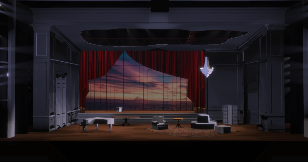

-
Peter, there is a way to do that through script sort of. You can open up the edit container, but not "in place" where you can see other objects while editing, but based on your prompt, that might be the desired effect since you're opening up the symbol edit through the Resource Manager anyway. As @michaelk stated, double clicking a symbol on a drawing will automatically open the edit container for the symbol after selecting which edit container you want to edit (though you can set one as a default). In any case, the script below will do what you are looking for. It will work on groups or symbols. In the case of symbols, it will open either the 2D component or the 3D component depending on what the current view is when you run the script. I should also note that it only works on objects that are one the active layer. One potentially huge caveat is that it will not launch the standard symbol edit widget, allowing you to switch between the 2D and 3D components without exiting the edit container. The key is SetObjectVariableInt with the selector set to 9743. It's one of those nifty things not covered in the documentation. PROCEDURE OpenEditContainer; {* Opens selected object's edit container based on current view Developed by: Jesse Cogswell Date: 3/23/2023 Revisions: *} CONST kEdit = 9743; kSymbol = 15; kTopPlan = 6; VAR h:HANDLE; symDef:STRING; BEGIN h:=FSActLayer; IF(GetTypeN(h)=kSymbol) THEN BEGIN symDef:=GetSymName(h); IF(GetProjection(ActLayer)=6) THEN SetObjectVariableInt(GetObject(symDef),kEdit,0) ELSE SetObjectVariableInt(GetObject(symDef),kEdit,7); END ELSE SetObjectVariableInt(h,kEdit,7); END; Run(OpenEditContainer);
-
Error Beep when using hotkey for Rotate
Jesse Cogswell replied to BartHays's question in Troubleshooting
This is a problem with Windows and not a problem with Vectorworks necessarily. The issue here is that on Windows, typically the Alt key is to open up items on the menu bar (Alt + F opens up the File menu, Alt + E opens up Edit, etc). Windows will throw the error tone when you use Alt plus a key that does not have a corresponding menu item, such as = for rotate. Any of the shortcuts that use just Alt in VW will throw an error (try using Alt + 1 for a Callout, or Alt + 5 for the freehand tool). Unfortunately, there's not much you can do about that outside of remapping any shortcut using Alt. You could open up the Windows Control Panel and go to the Hardware and Sound category, and clicking Change System Sounds. I don't know if what you are hearing is the Asterisk sound, Default Beep, Critical Stop, or Exclamation as they all the same (at least on Windows 10).- 1 reply
-
- 1
-
-
@setdesigner Let's see if this works, I've exported the settings I have for VW 2019-2023 as a file. You would import them by More then Import Settings. I've never done this so I don't know how well it will work, but it's worth a shot. I can't attach the file directly since it's not a forum-supported file type, so I've zipped the file. Let me know if you have a hard time getting this to work. JNC VW 3Dx Profiles.zip
-
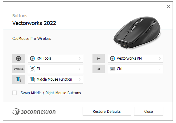
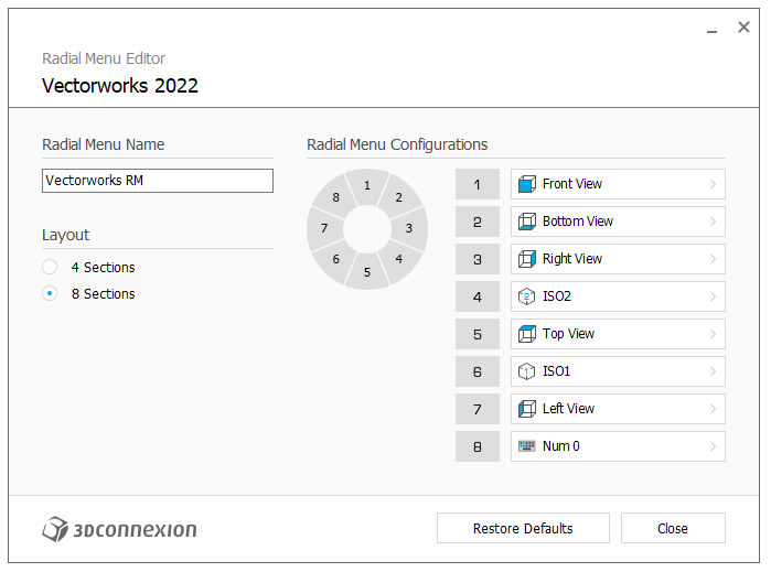
I love my CADmouse and really can't draft without it. I use it to primarily drive views, which all have shortcuts built in to the 3DConnexion software. What I currently have set, and am very happy with, is to have the mouse wheel be my "Fit View" button, my forward button launch a radial menu with views, and my back button to mimic the Ctrl key (makes Ctrl dragging and clicking to copy objects super simple, and gives me a one hand flyover view by using it in conjunction with the dedicated middle mouse button). My radial menu looks like this: All of the standard views are found in a category named Views, except for Top/Plan. For this, I just typed in a shortcut with numpad 0. Undo and Redo commands can be found in the Macros category, but for dedicated Vectorworks tools you will need to do them as keyboard shortcuts (by default 1 for text, 2 for line, = for mirror, etc). I also recognize that you are working with a different version than I am, I am on 10.7.4.3350 and won't be upgrading until it forces me to since it currently works between versions 2019 and 2023. @Tom W. There is a slight bug which I don't know ever got patched where XML files were missing for some versions of Vectorworks, causing 3DConnexion devices to use a generic Vectorworks profile (no year number listed), which would wreak havoc in doing setup and jumping between versions of software. I remember this being the issue with 2023 when I first downloaded it. If you launch the editor and it DOESN'T list a year number after Vectorworks, then you need to add a new profile by following the directions below: In an explorer/finder window, navigate to C:\Program Files\3Dconnexion\3DxWare\3DxWinCore\Cfg (on Windows, no idea where it is on Mac but it's likely a similar file structure), this is the location of all of the XML files. Find a "numbered" version of a Vectorworks profile (like Vectorworks2022.xml) and make a copy of it in the same directory, renamed to match the version number you need. In a text editor, open the XML file and change any listing of the Vectorworks year to match the one you need. Your device should now properly be able to create and edit profiles for that version of Vectorworks.
-
After doing a short experiment, my script currently does not find classes that are embedded in plug-in objects. I feasibly could add that (and will when I get time), but it would require "stepping through" every plug-in object in the drawing to track down components using the target class. In all honesty, the special record formats should have no real bearing on classes unless the VW file contains a referenced copy of the plug-in object to go along with the record format, and even with that addition my script would not have caught the Component-Landscape class since the object itself did not contain the class (though that might be because I don't have the actual plug-in installed). I just did a test with one of my own PIOs that has an embedded class (set in the OIP, not hardcoded). When I have an object in the drawing and try to delete the embedded class, I get the warning. However, if I delete the PIO so that there is no longer one in the drawing, I can delete the class without any issues. But the major caveat is that my PIO does not use Styles, so there might be something more tied up in Styles preventing what I would call "normal" operation. I have not incorporated Styles into any of my plug-ins, partly because the documentation isn't very well defined and partly because I have a bit of an aversion to Styles cluttering up my Resource Manager and generally feeling clunky to use.
-
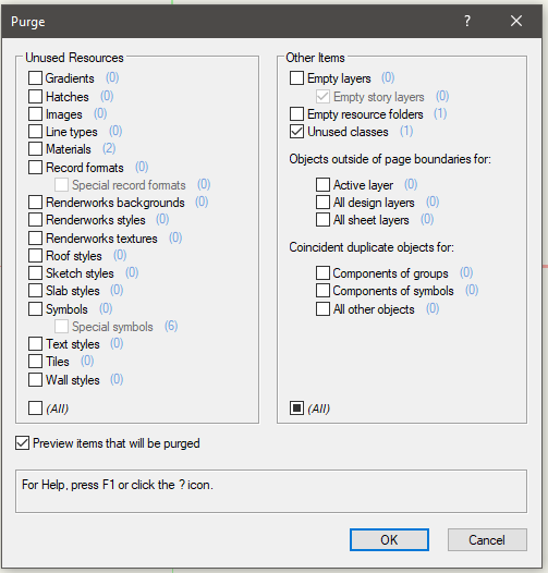
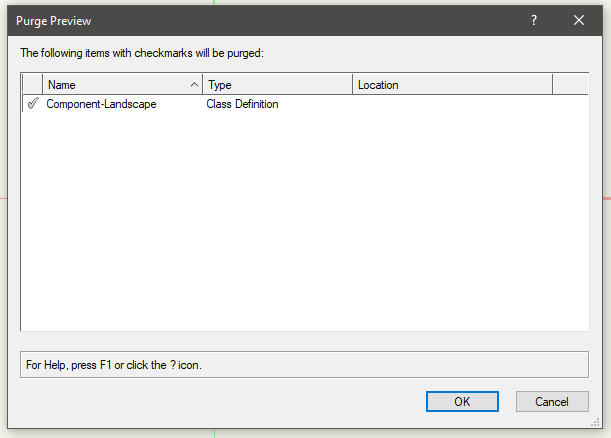
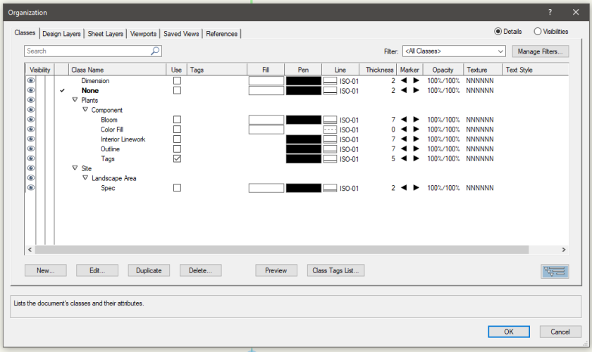
Okay, I looked at your file and think you've found a bug. If I open up the Landscape Area Styles in the Resource Manager and delete the Meadow and Prairie Perennial Garden, VW will not let me delete the Component-Landscape class from the drawing, showing the error dialog that you shared earlier. However, running the Purge command will now show the class as being unused, and will safely remove the class from the drawing. So, for some reason deleting the Style is enough to show the class as unused for Purge but not for the Organization dialog. I don't have the Landscape module, so I can't interact with the Landscape Area plug-in, but looking through it, nothing in the Object Info Palette references the Component-Landscape class and stepping through the object after converting it to a group also does not reveal anything in that class. My guess is that the class is hardcoded into the plug-in object (from a programming perspective, this is a bit of a dick move), so it doesn't follow the standard "rules" of whether the class is in use or not.