
JustinVH
-
Posts
597 -
Joined
-
Last visited
Content Type
Profiles
Forums
Events
Articles
Marionette
Store
Everything posted by JustinVH
-
This has not been implemented yet. You can use Magnets to place the truss at a mid span point but you cannot calculate Braceworks. As far as I know the calculation part of this is not yet on the horizon and I believe it may be due to safety regulations and some countries not allowing it. @Scott C. Parker may be better to confirm the safety regulation and allowance reasoning.
-
Good idea on making the second version of the symbol. I can't do that with the content because we try to not have duplicate symbols but I did not realize there was a flip issue when I setup the file. I would flip the geometry along the X axis as opposed to flipping the magnet polarity so that the forks correctly lock into the receiver as the flipped polarity might cause the visual geometry to be incorrect. Basically a symbol that looks like a 7 and then another that looks like a L. Sounds like you have the solution well in hand for your office so I will let you get back to it and let me know if you need help. If the workflow changes after some discussion I will make sure to let you know so that you can adjust if needed.
-
The issue is the magnets for the truss connections. The GT truss is fork end so it uses the male/female connections to make sure that the truss will build properly in both directions and the correct ends will connect to what they should. This is causing the issue with the gates because the software is relying on looking for the opposite gendered connector to what it is connecting. In order to flip the gate to the lower connection the program is looking to flip the symbol but it cannot because that would be connecting the same genders which the code will not allow. I was able to get the gate to flip properly by changing the auto connect settings to Neutral for all connections on both the truss and the gate. You will have to do this in both the truss properties and the 3D symbol where the magnets are housed. Once all connections are Neutral the expected behavior will occur. Just be careful, because you may run into issues where you are getting forks connecting to forks or receivers connecting to receivers depending on build order. I am going to look into the issue further and file a bug and discuss with the engineers but for now changing the magnets will cause the expected behavior to occur. I build all the truss and set the connections for the shipped content so that is why I am hesitant to blame the content. I want to make sure that there was not something missed in the code when the engineers created the connections and magnets. Let me know if you have further questions or need help. Justin
-
Is this a stock truss symbol or a custom symbol that you or someone else has created? I can get auto connect in both directions with gates. Is it possible to send the file and I can take a look? You can DM if desired.
-
The entire catalog with resources is well over 50 GB and probably closer to 100 GB which is why it is stored on the cloud to be called upon when it is needed. If you do have the content on your hard drive you will also not receive the automatic downloads when the Resource Manager is updated as the cloud gets updated but not the local hard drive.
-
@ZrasapThe fact that the user created structural data did not get imported is works as designed. Custom structural data can only reside in the document in which it was created and cannot be imported or transferred to another document. This is a safety check put in place by Vectorworks and the developer of Braceworks to keep potentially incorrect and non verified structural data from being spread through the user base. I am afraid if you want to keep the custom structural data on the truss you created you must stay within the document, add it to the truss each time that you use it in a different document or work from a template file where the truss already resides.
-
@ZrasapDid you run a Braceworks calculation on your custom truss? The grey box from your screenshot is usually what happens when you run a calculation on a truss what does not have structural data and is instead set to Rigid.
-
@VectorWorker22It looks like the Rigging-Truss-Simplified class is turned on in your document. That class is a simple extruded shape so that you can see what area a truss occupies but not slowing your drawing down with all the webbing. Turning off this class will reveal the truss underneath, I can see the 4 main chords on the left side of your drawing.
-
@Brent.A This is 100% true that Tomcat will not share the data with us. We have been informed by them that we will never be given this data for two reasons. The first is because of liability reasons with the calculations being incorrect and the potential collapse of a rig if Braceworks said it was okay and the second is that the company which certified the truss initially will lose money as Braceworks users can use the software to make sure the rig is close before sending for actual certification by a structural company. If users only need to have one certification performed as opposed to several along the design phase there is lost revenue. For US truss manufacturers the only company that has provided us certified data that has been turned into Braceworks data is Christie Lites. A large portion of EU truss companies have provided the data as the EU is a far less litigious region. All we can say to do is to contact Tomcat and their parent company Area 4 directly and express your displeasure about not having this data and that you will have to look into alternative truss that is compatible with the software. This was done with Tyler truss and we are in the process of completing what is needed to get the data into Vectorworks after an initial holdout. Ultimately, this will come down to the users of both Vectorworks and Tomcat truss to complain enough to the manufacturer for them to realize that they could lose customers as a result. Feel free to DM me is you have any more questions.
-
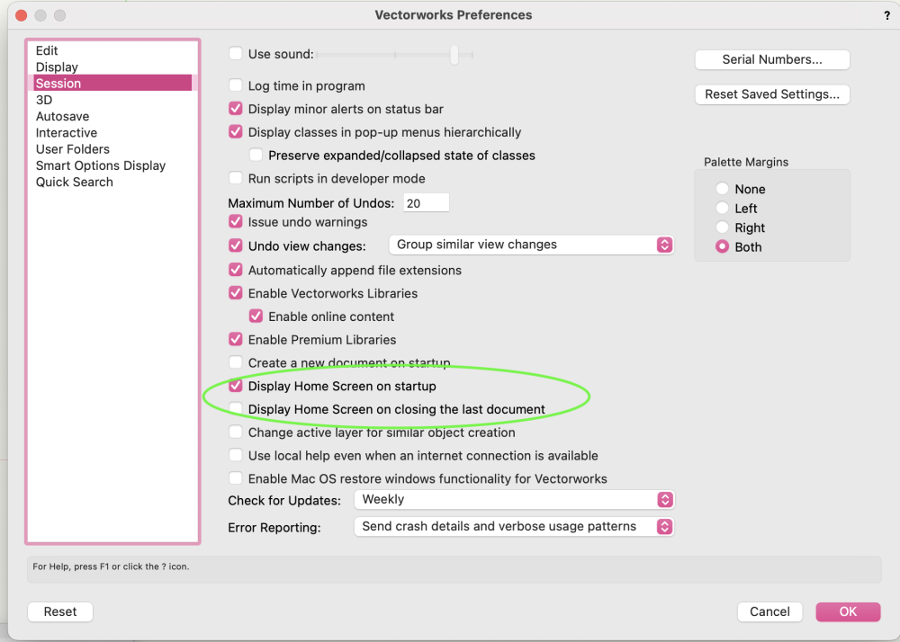
The settings are in the VW Preferences dialog.
-
If you also search for 'restrooms' in the RM there are two mobile restroom trailers. Not exactly porta pots but it is something.
-
@spettittAt this point in time center point hinges cannot be setup in the orientation that you are asking. Center point hinges can only be setup with the rotation point being viewed from the front so that the hinge pivots towards the negative and positive Z directions. In order to insert this hinge so that the rotation is through the Z axis like you have pictured you will need to change the roll angle to 90° at insertion. The error you are seeing is because there is no height and width dimension in the Cross Section Data of the the truss. Currently it shows a measurement of 0, simply change this to the dimensions of the truss box and that error should be eliminated.
-

Duplicate truss crosses in the same plane / space
JustinVH replied to Mark Aceto's topic in Braceworks
If you change the offset of the truss cross symbol in the record it will change the thickness. You may have to adjust the insertion point but I thing you can go down to 1mm of offset if you need a really thin connection. You will also have to adjust the 3D extrude thickness of the symbol that you make to get the visual to not clash. -
How to remove a truss pick-up symbol from a hoist?
JustinVH replied to Mark Aceto's topic in Braceworks
If you are using VW2023 there is now a "No Symbol" option in the Truss Picks folder. This will allow you to remove the truss pick without disconnecting the hoist. -
@ABohmWhat license do you have? Architect, Landmark, Spotlight, or Design Suite?
-
You should reach out to Tyler and hound them to provide us with the weights. Last time I spoke to them their exact words were "we don't know the weights of our trusses, we just weigh them before they go on the truck and calculate that way. If they can get VW the weights this can be added in the future.
-
In VW2023 there is a new data tag for hoists that replicates the behavior of the coordinate label in the old hoist tool. It is identical with the arrows and will scale properly in the drawing. That tag is located in the Hoist.vwx file in the Entertainment Data Tags folder and is called Hoist Tag-Hoist Label.
-
@OaktownI will DM you a test file.
-
Fixture beam visibilities - How to activate deactivate?
JustinVH replied to ChollyO's topic in Entertainment
@ChollyO You will need to go into Document Preferences and turn off the 8 light limit for Shaded rendering. Once you do that you should be able to see all the lights in either Shaded or FQR.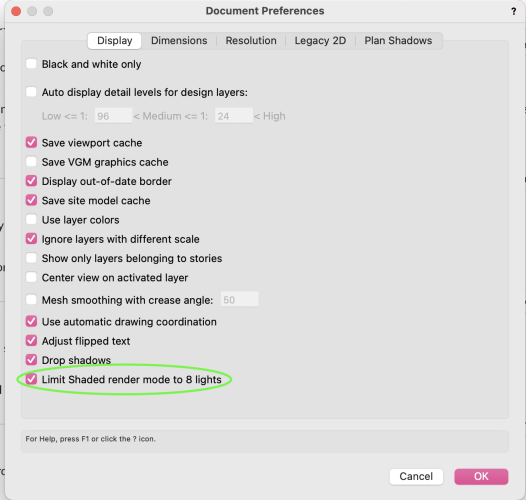
-
Fixture beam visibilities - How to activate deactivate?
JustinVH replied to ChollyO's topic in Entertainment
It looks like you are using VW2022 from your signature. If that is correct and you are using the Shaded mode for rendering there is an eight light limit for beam visibility so only eight beams will be rendered. -
Units not changing in Resource Manager
JustinVH replied to HaveCamera_WillShoot's question in Troubleshooting
Also all of the code for truss is in metric units so it is easier for the CAD Content team to work in metric because all of our internal scripts require metric units. You may find some manufacturer truss records that have imperial units but this is rare as it requires the team to have to convert units back into metric when do final setups before release. -
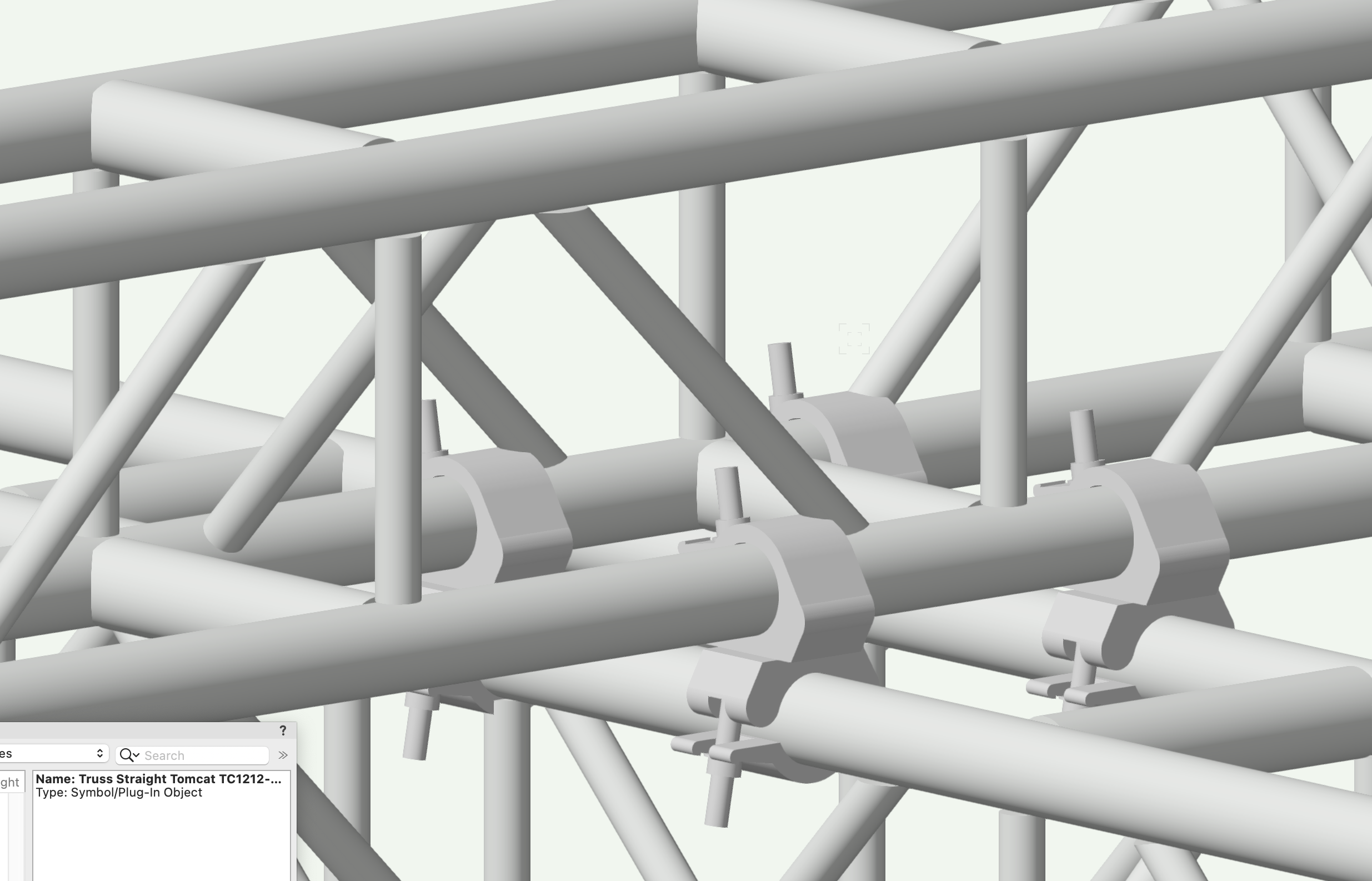
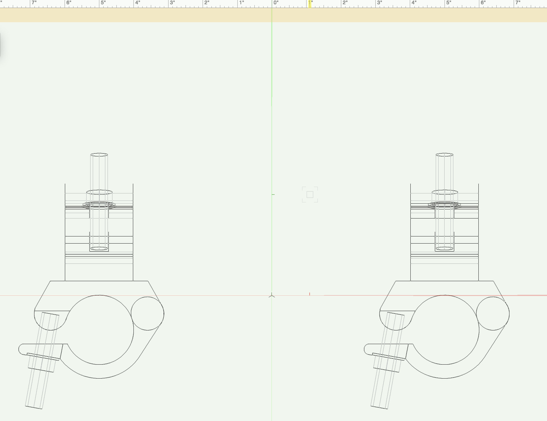
@OaktownI was able to get it to work using cheeseboroughs. I set the offset to 20.75mm and made sure to adjust the insertion point of the symbol accordingly. I have included two images to show how my cheeseboroughs look and how I have setup the 3D part of the symbol. I am using Tomcat 12x12 truss. Note that the 3D loci in the 3D symbol setup is at (0,0,0).


-
@AdamG At this point I think it is best to reach out to tech support to see if they can help you resolve the issue. I have included the link to the support request page. https://www.vectorworks.net/support/help
-
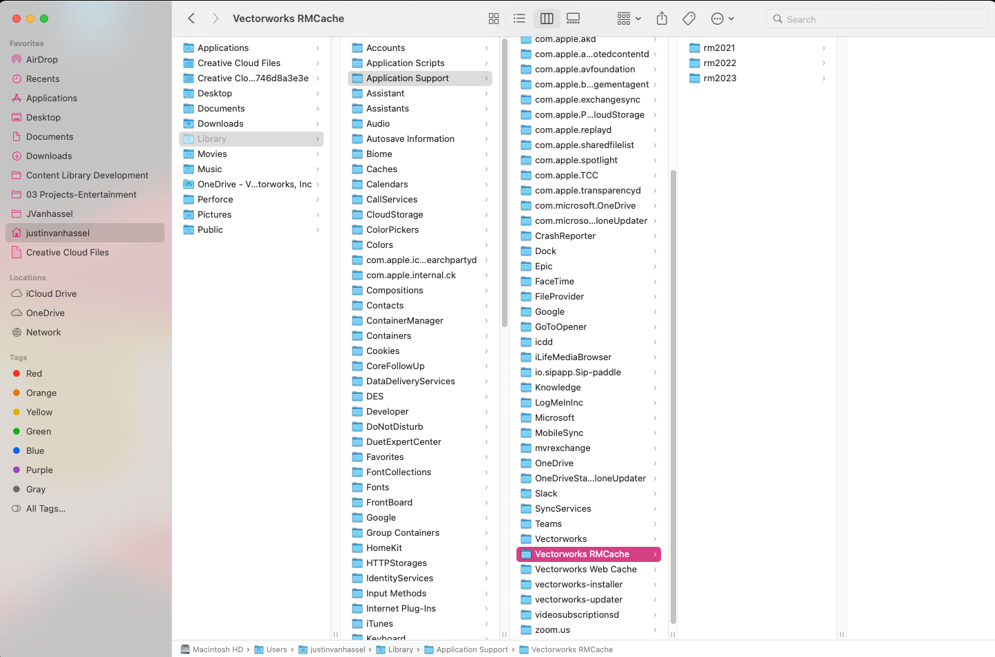
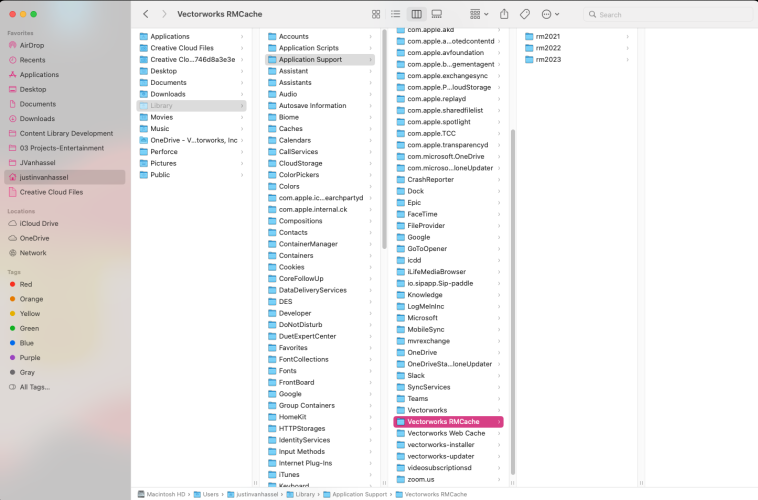
It is through the Go menu but you have to make sure to press option so that Library reveals itself. Here is a screenshot of the path.
-
Also note that if you are rendering your large previews using shaded you can gain a little quality buy switching your shaded options to High or Very High quality. It is marginal and it does not make the image bigger but there is a little difference. If you have draw edges on the preview will also draw those edges and in such a small window it can muddy the image.