
Jeff Prince
-
Posts
2,946 -
Joined
Content Type
Profiles
Forums
Events
Articles
Marionette
Store
Everything posted by Jeff Prince
-

Can you pick up new site levels from a modified site model?
Jeff Prince replied to LisaCoxGardens's topic in Site Design
Well, if you are staking a hardscape that has thickness, you would not reference the site model in the stake setup would you.... 🙂 You would stake the hardscape object. -
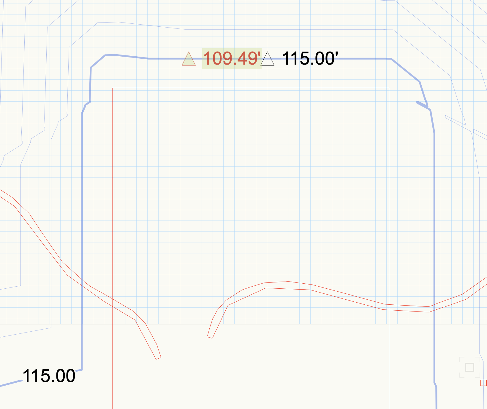
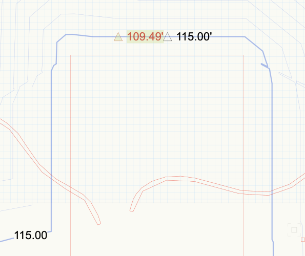
Can you pick up new site levels from a modified site model?
Jeff Prince replied to LisaCoxGardens's topic in Site Design
The stake tool is capable of displaying either the existing or proposed elevation as you noted and regardless of how the site model is set to display (existing vs proposed). Are you sure you have your stake configured correctly? If so, it should work. Example of how stakes should behave. Left one is set to Existing site model, right one is set to Proposed. Blue contour is proposed 115'.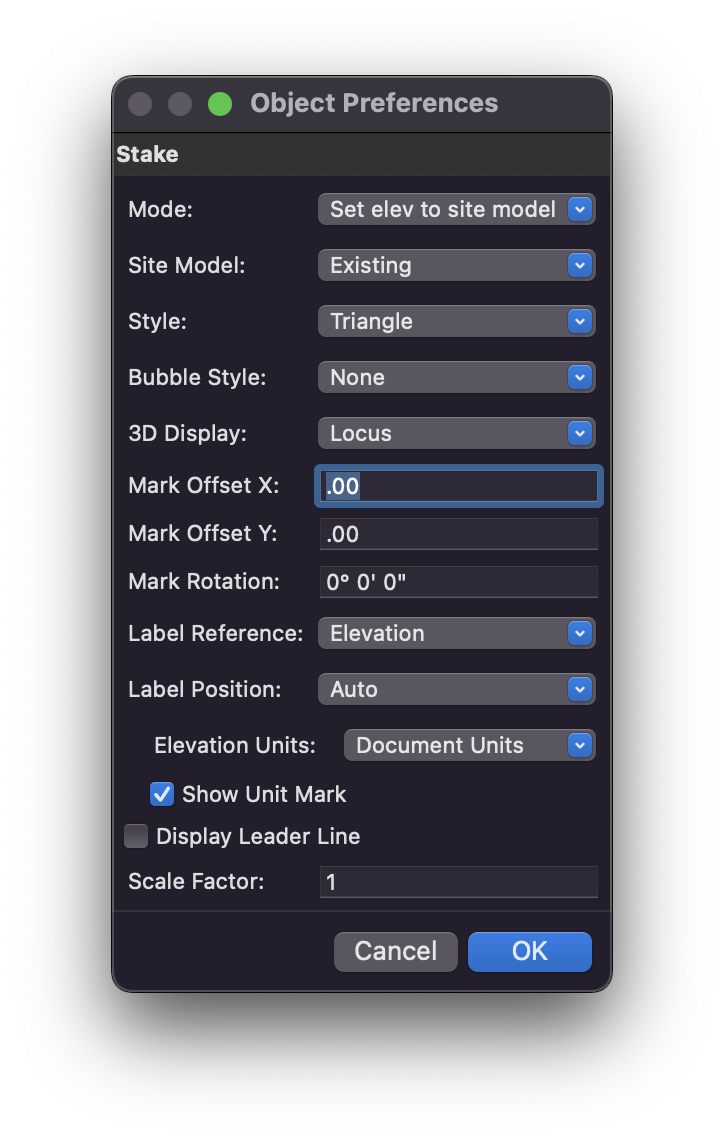
-
Worksheet not picking up landscape area plants
Jeff Prince replied to Nic_Berry's topic in Site Design
That's why he can't get the reports to say what he wants. I don't see how it's possible using a class methodology to distinguish between plant types with mixed plantings as Landscape Areas. You need different criteria for organization. I don't think you can accomplish reporting the plants in a LA by class due to the way vectorworks builds LAs as I mentioned earlier. However, you could potentially use the Field "Category" and use the values in there to report out how you want, assuming you have been or will populate the Category field appropriately. Adding this to your criteria for instance in place of a class methodology might work, I mean that's one of the reasons it exists... so you can organize your plant list by Category or quantify all the trees on a project for instance. Just watch out for Shrub vs Shrubs and such... ('Plant Record'.'Category'='Shrub') -
Worksheet not picking up landscape area plants
Jeff Prince replied to Nic_Berry's topic in Site Design
You can build your symbol geometry on different classes as part of the Plant Object creation process and it will be preserved within the Landscape Area. However, during LA creation those symbols will all be inserted on the active class, so it is not immediately apparent that nested classes are at work. -
But never use that tool when you have an important drawing open, it's a recipe for disaster. Like most things, best to import into a clean file first.
-
That's good advice. Landscape Forms seems to do a great job of getting their content into Vectorworks. They are also awesome to work with on projects, bending over backwards to help you along every step of the process. Consequently, they get spec'd and installed on lots of public work. Same thing with Tuuci umbrella, they probably sold over a 100 of those rectangular cantilever units just because I found them in the Vectorworks library 🙂
-
Yeah, but how to you get consensus on what is a "decent" plumbing fixture? Anyhow, we've spent more time discussing it than it would take to actually model something from scratch at this point 😉 It's probably faster to model something than searching the VWX library too, unfortunately.
-
You are specifying a plumbing fixture for a job, does the manufacture provide you a Revit object you could import into Vectorworks? Institutional stuff like ADA compliant bathroom fixtures should be pretty easy to come by. That seems like a big ask of VWX, I'de rather they focus their resources on fixing the software wouldn't you? It would be a never ending quest trying to keep up with all the manufacture's offerings each year and then making them optimized for Vectorworks. Revit & DWG seem to be the standard for manufacture provided BIM objects for a reason.
-
Well, you could edit your Plant ID to reflect your SKU if you want a tidy work around 🙂 Probably not a good idea for contractors who actually use the SKU to place orders though... Anyhow, you have limited ability to control the plant tag. For instance, you can not configure the tag to replace the ID in the Bubble to the SKU. You can turn off the Bubble and instead use Top, Center, or Bottom tagging to get close to what you want, sans rectangle. Then, do as @Tom W. suggest and use "set custom tag" to configure the displayed data as you wish. Plant Tag text styling is a bit more problematic compared to data tags. You can only use one Text Style for the entire tag, so no use of Bold or Italics for instance on part of the Plant Tag (you can do that with a data tag) You must use the Vectorworks default class for Plant Tags in order for Text Style updates to carry through automatically, so all plants will have the same text style regardless of phase, plant type (say tree vs ground cover), scale, etc. If you instead us the class the object is placed on to govern the Text Style, the plants won't update if they are moved to a different class because of how Vectorworks treats the application of text style to objects vs objects during the creation process (using a plug-in or similar, to make the geometry and features). A good practice is to create a Text Style for your Plant Tags and give it an easy name to remember (like Plant Tag Text for example). That way you don't use it for other things and have those things change later if you decide to restyle your plant tags. I've seen this happen so many times where people use the same style for general notes and then want to get cute with their plant tags and use a hand drawn style. Chaos ensues. Good luck with those built in Plant Tags.
-
Crittall Glazing / Conservatory / Green House
Jeff Prince replied to InchSw3's topic in Architecture
@InchSw3 are you designing this for manufacturing, rendering, or something else? If you need 3D modeling, I would approach it by making the various parts as 3D solids and "assembling" the building like you would do in real life. BIM tools like doors, walls, and windows are probably too much trouble for a specialized structure like this, especially if you have to detail it. If you don't need 3D, 2D drafting can get the job done far easier, especially if you are using off the shelf components & standard extrusions. -
You need to switch to Data Tags to do what you wish effectively. Plus, I suspect Vectorworks is abandoning all these built in tags in favor of Data Tags based on how things have been progressing. Better to switch now and get things working the way you want IMHO.
-
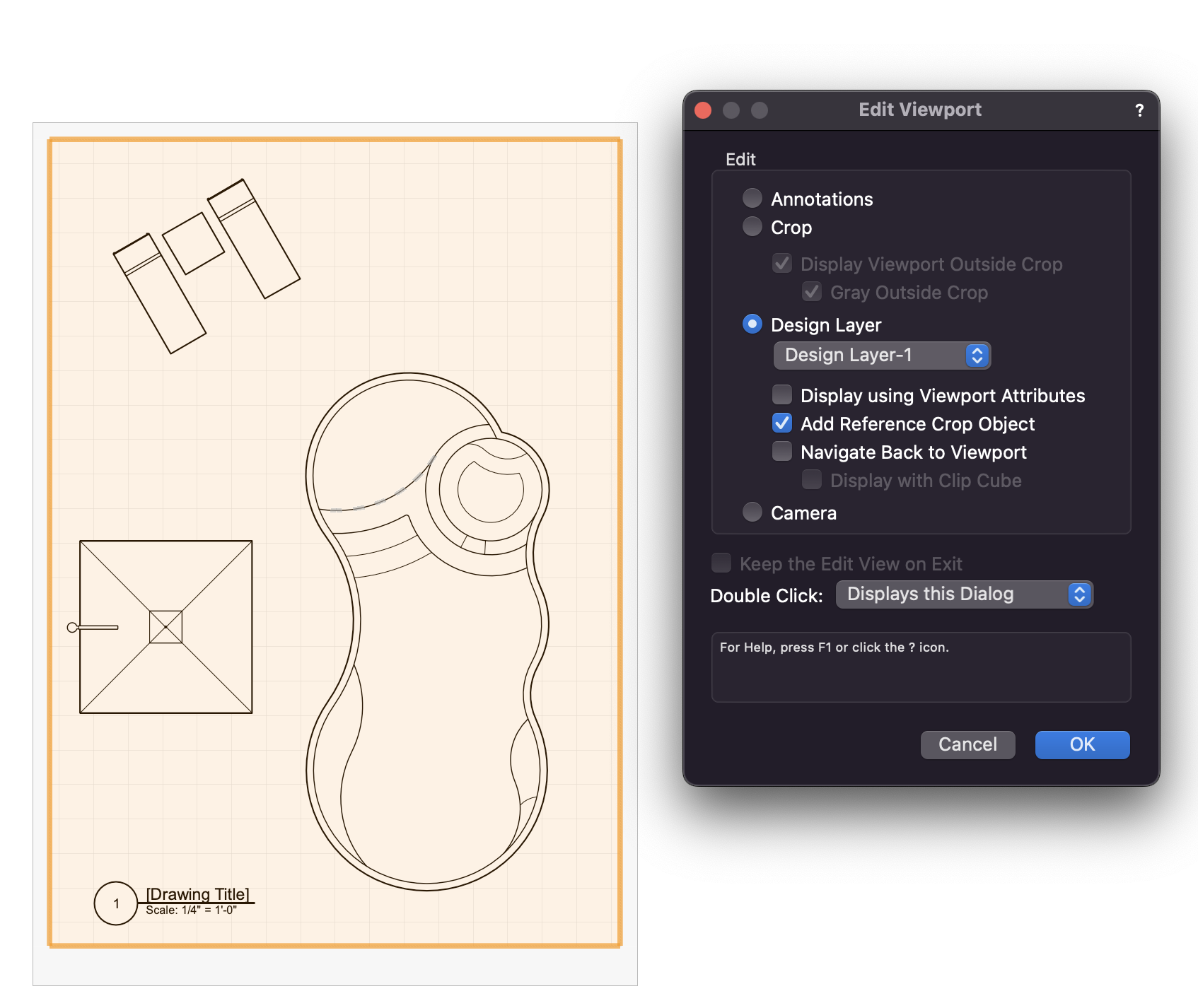
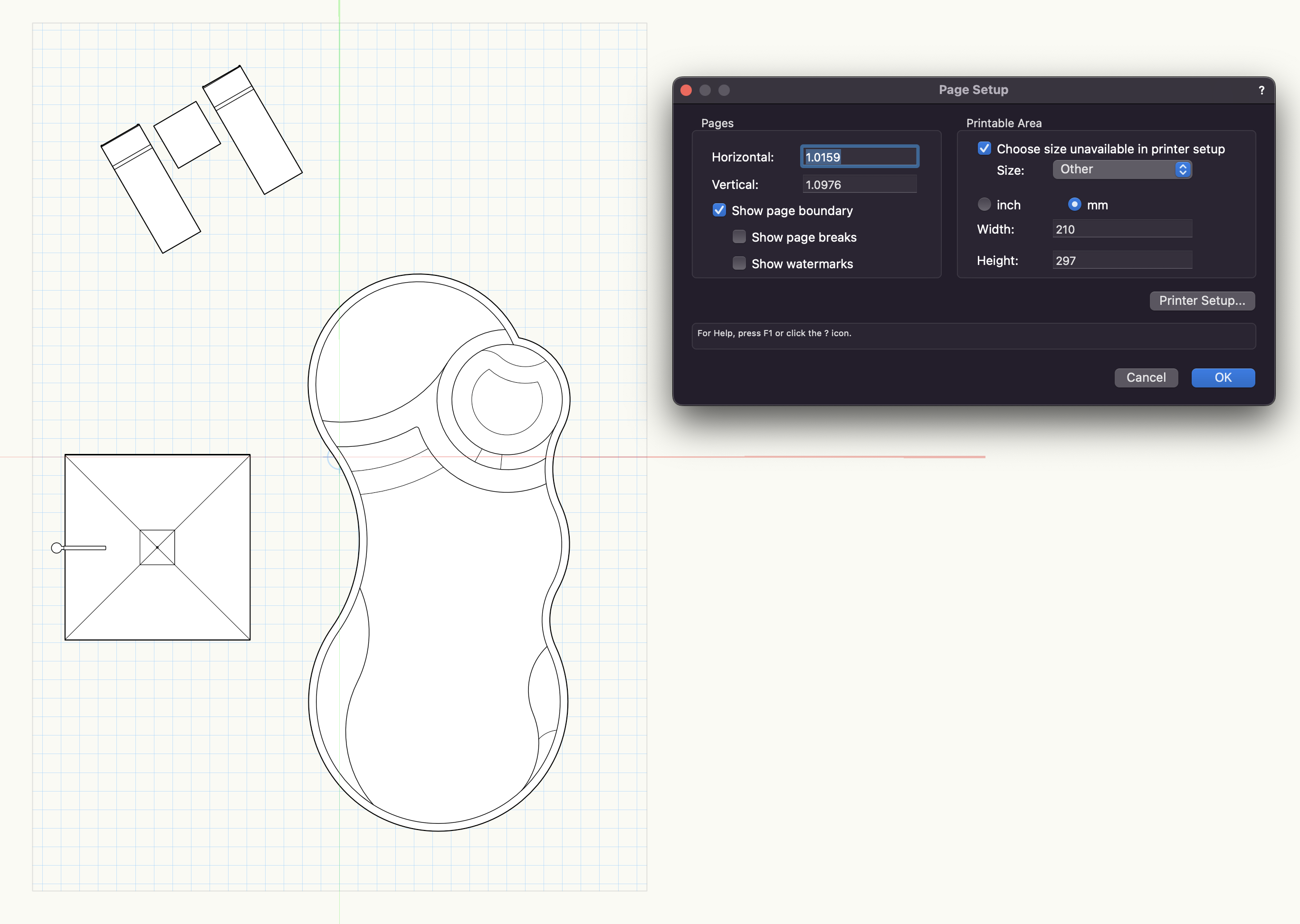
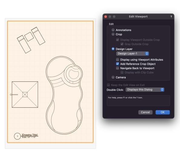
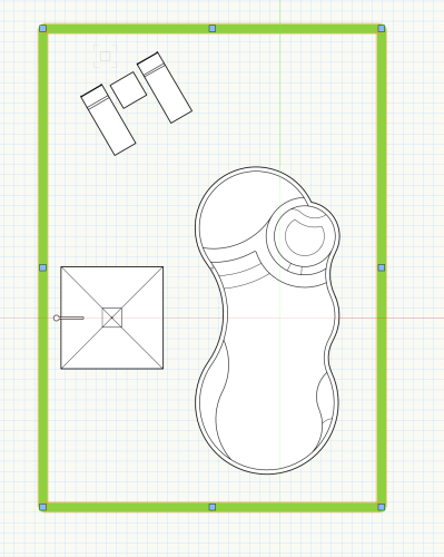
Sure, it's easy. Go to your sheet layer and double click on the viewport. The Edit Viewport menu appears, set it like this: You will be transported to your design layer and will see a big green rectangle which represents the extents of the viewport. You can then change the rectangle's graphic appearance to suit your needs. One other thing you can do from a design layer viewport to get a sense of the paper size is to use Page Setup while in a design layer and select "Show Page Boundary". The reults can be seen in the image below... basically stops your grid at the extents of the page, which might be a good visual cue.

-
Change your design layer scale to match the viewport scale. Then, from the viewport, enter the design layer. It will ask you if you want to place a representation of the viewport on the design layer (it’s just a green rectangle you can change with the attribute panel). that will give you a pretty good match with your sheet layer in terms of viewport spacing.
-
If accuracy is important, it's not the first tool I would reach for. I find the iPhone LiDAR to be equally as accurate, but provides far more useful information for 3D modeling.
-
Just curious.... Why would you need to have every plant object called out with a data tag? Doesn't that create some messy plans for you? I use symbols and plant legends to insure the right plant is put in the correct place with accurate quantification data. The only plants I call out data tag or note are existing to remain/protect, special specimens, or unique situations that need extra attention.
-
Lock Site Model!
Jeff Prince replied to ericjhberg's question in Wishlist - Feature and Content Requests
@ericjhberg 's suggestion is extremely valuable. It's a logical expectation that your site wouldn't move while manipulating it, it's supposed to be a geolocated representation of the real world after all. I teach people how to site model and accidentally moving it is the number one mistake people make when editing the site or just generally using Vectorworks. The next one is not setting up their model to listen to the correct design layer for site modifiers. This usually happens right after they get so tired of accidentally moving their site that they decide to put it on a separate design layer from the modifiers and everything else to avoid the problem. Making a model position lockable, but otherwise editable would be a huge improvement. -
what makes you guys think otherwise?
-
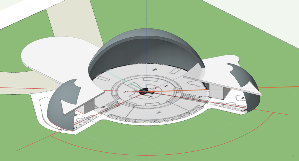
Having looked at this house, you might consider a different angle before committing to this drawing. If you rotate your drawing 90 degrees counterclockwise, you will be able to reveal the inside floorplan much easier. This reveals the building via it's window walls and open structure. Compare this to your current layout where you will primarily see the curved roof and little of the interior without doing a cutaway. Here's a mockup of how I would portray a building like this, but keep in mind Vectorworks doesn't do true axonometric projection, this is the isometric. To lay this out by hand accurately, you would need to cut a few horizontal sections to lay ontop of your ground floor on trace. This would give you the ability to move the horizontal sections up and trace them. I think two would do it and you could connect the curved section of roof through the horizontal sections. The building isn't spherical as I have depicted, it's more of an oblate spheroid as you have shown in your nicely illustrated section and elevation. The French curve will be handy for illustrating the roofs.
-
Cool. It was tricky for me to explain it succinctly 🙂
-
I believe it works like this: It takes the ratio between the current screen zoom value and the drawn marquee's longest dimension (in screen units) and applies that to the current screen zoom. Example: Your screen shows a 10m x 10m square centered on the screen at a zoom% value of 233, which is displaying an area 20m tall. You draw an "option+zoom marquee" which is 10m tall and 5m wide, which is 50% of the current screen height. This results in a screen zoom% of 116, displaying an area 40m tall. The 5m width didn't factor because it was the short side of the rectangle, only the long side is used.
-
That’s a tough assignment. Did you choose the building? If so, ask the professor if you can choose something more appropriate for learning how to do an axo 😉 This author covers almost every graphic technique you will need for architectural presentation, including the antiquated hand drawing of axos. https://www.amazon.com/Architectural-Graphics-Francis-D-Ching/dp/111903566X
-
AI command interface for Vectorworks
Jeff Prince replied to Christiaan's question in Wishlist - Feature and Content Requests
The number of high skill employees required to create and document a project has radically declined over the past 50 years, and that is largely due to drafting improvements. When that part of the profession is further automated, fewer people are needed and the important “wax on, wax off” tasks that help train young professionals will be gone. When people start letting AI do the creative part, they are slitting their own throats. If you want to see the future, just look at manufacturing. AEC has always lagged a good 30+ years behind that industry. @BartHays mention of the graphic designers is another good example. That profession has been largely converted to a commodity traded on price. That’s been happening to commercial architecture for quite some time. At any rate, it will be interesting to see how it all plays out and identifying opportunities to profit during the disruption. -
AI command interface for Vectorworks
Jeff Prince replied to Christiaan's question in Wishlist - Feature and Content Requests
Unfortunately, AI will be doing almost all the stuff within your lifetime. Licensed pros will be required to sign off for liability purposes, until those laws change. So, the tedious process of checking the AI "design" so stairs don't look like a rip off of a MC Escher design will still be needed 🙂 It's going to be like the transition from manual drafting to CAD to BIM... only instead of outsourcing to India, you will be outsourcing to the cloud. -
Floor line in the middle of the wall in section.
Jeff Prince replied to Leandrovsk's topic in Architecture
Too concise… I forgot to put “don’t” after the comma 😉 -
AI command interface for Vectorworks
Jeff Prince replied to Christiaan's question in Wishlist - Feature and Content Requests
If that’s the case, I wonder which company is going to successfully develop the successor to the architectural design and documentation process. AEC AI will probably follow the Revit -> Autodesk path, with a big fish swallowing up a smaller one. Innovation like this rarely occurs in house, especially when radically different tech is being developed. The old guard typically resists this and it takes outside eyes to shake it up. The company with the deepest pockets is probably going to win.