Gadzooks
-
Posts
509 -
Joined
-
Last visited
1 Follower

Recent Profile Visitors
3,627 profile views


-
If you don’t have the resources just Google it and find an online ‘icon builder’. There are quite a few. (Generally) Upload a file, set your icon size from a list and use the output.
-
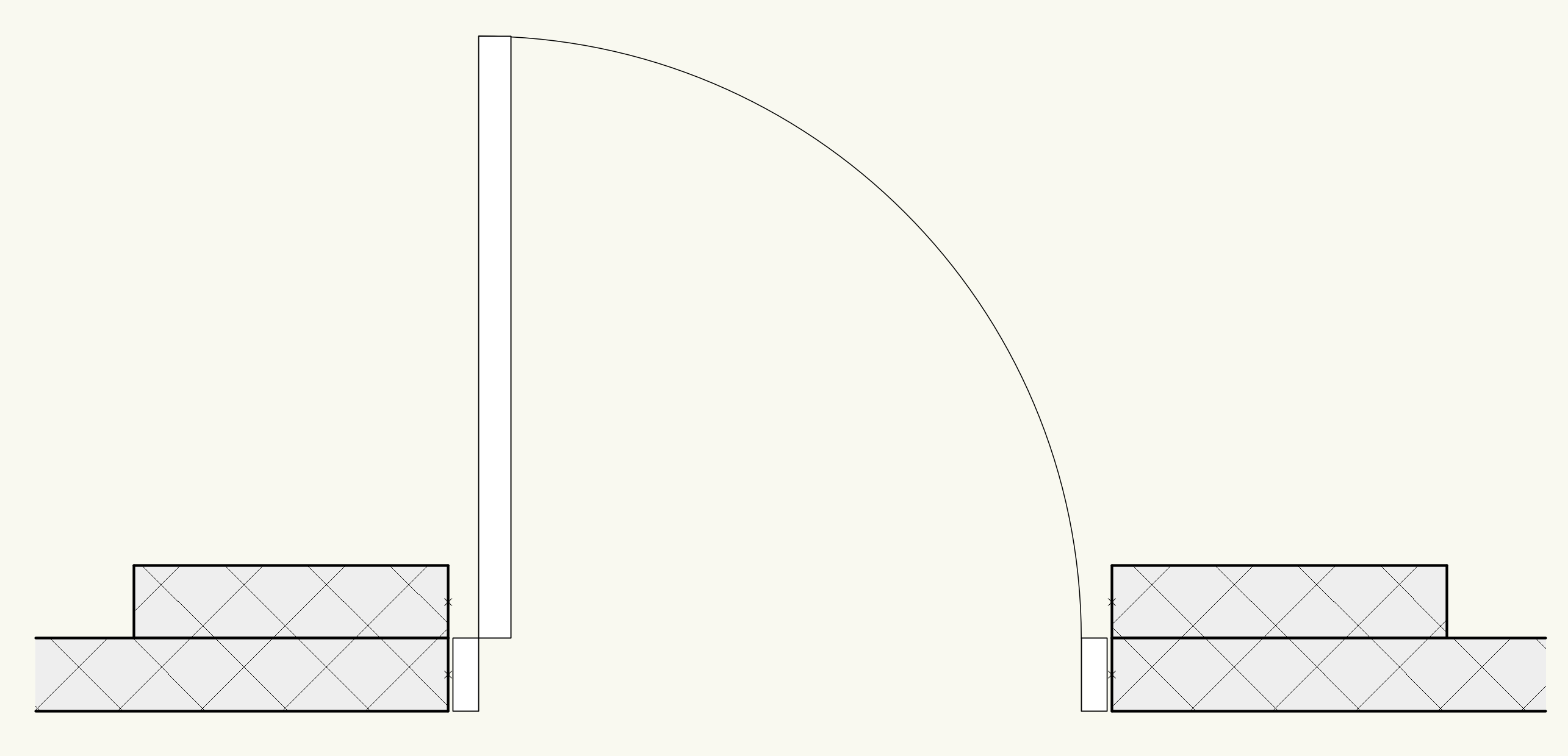
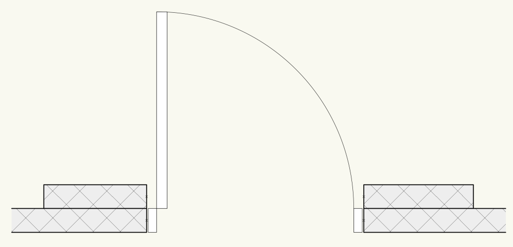
If it's a single operation, fair play to Revit. But you could get the same effect using wall recesses to punch a starter hole in both walls then place your door more centrally if it needs
-
For an uncomplicated solution, I would use a 'door' for one wall and an 'opening' (with the same dims) for the other wall.
-
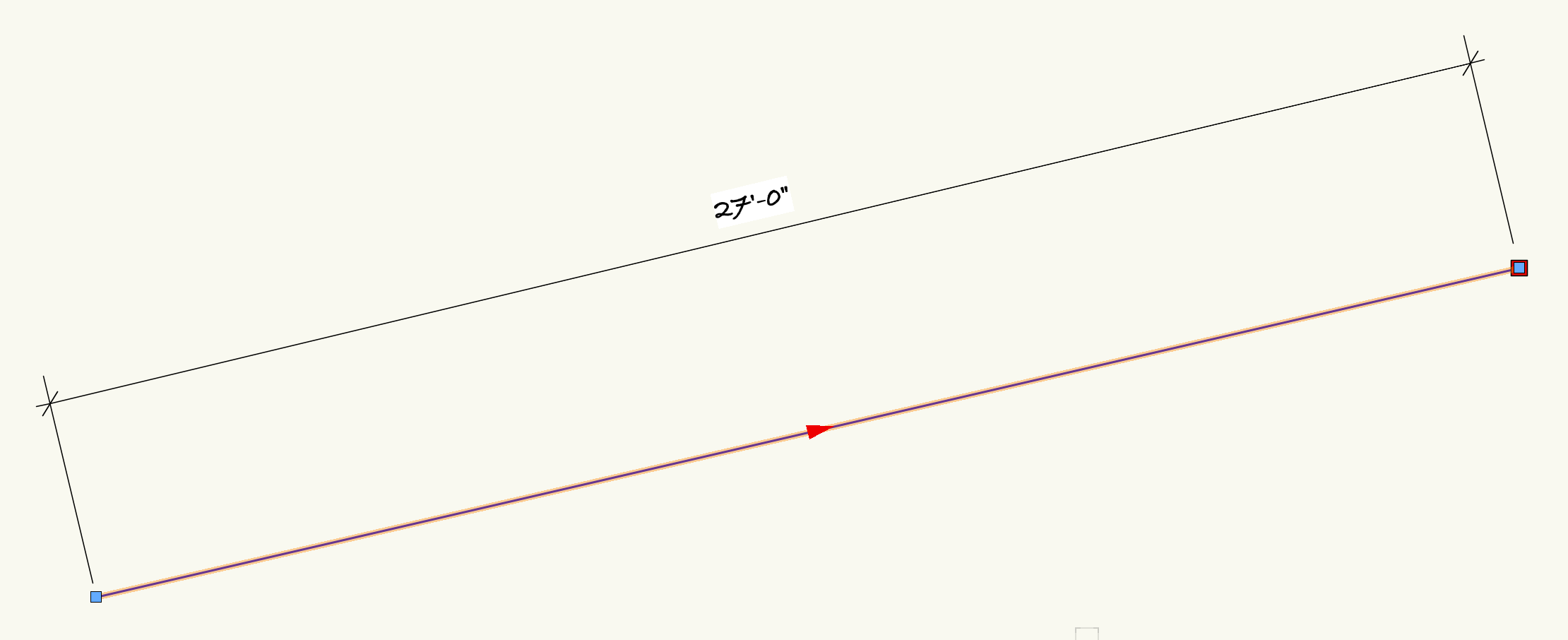
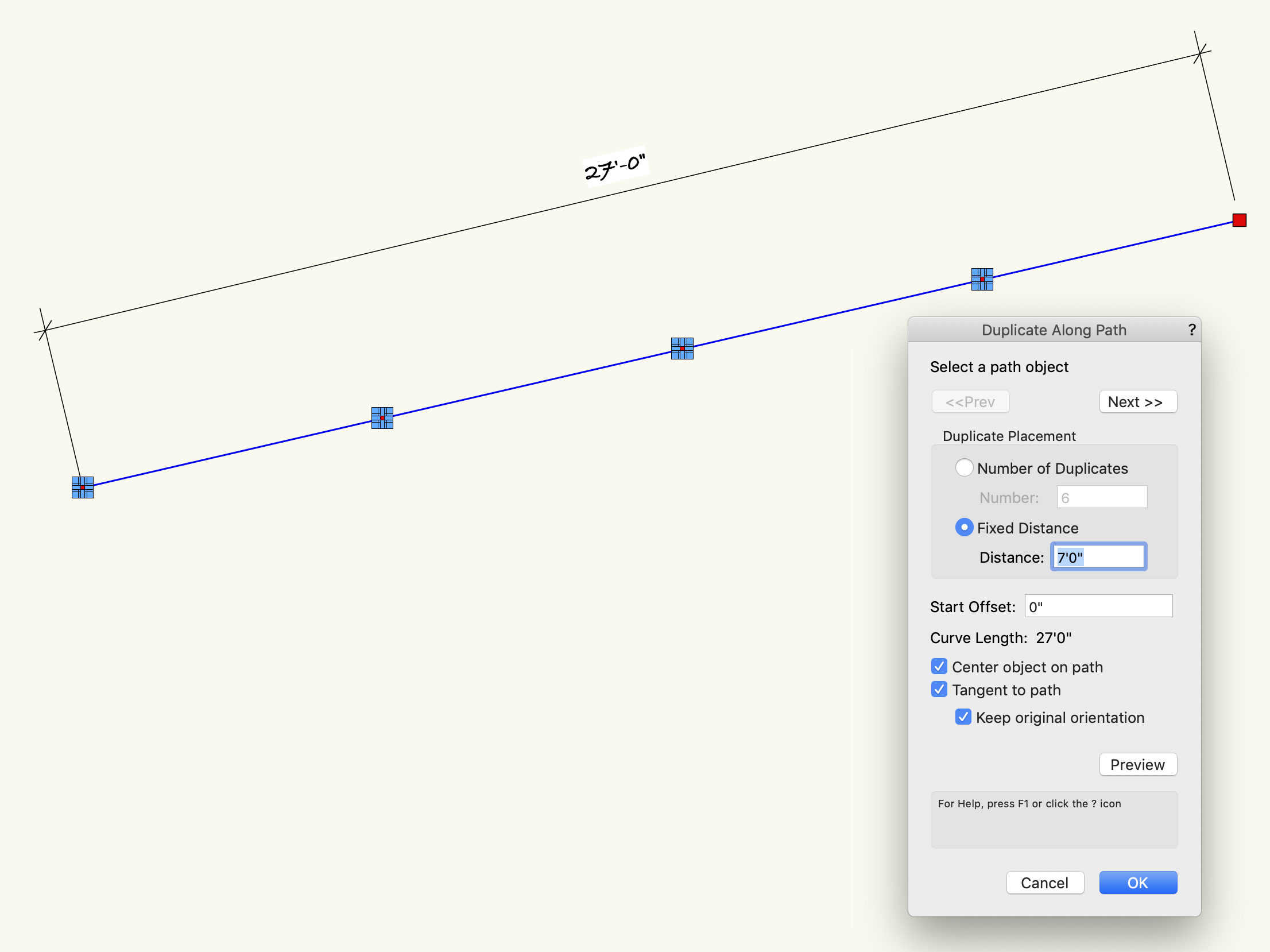
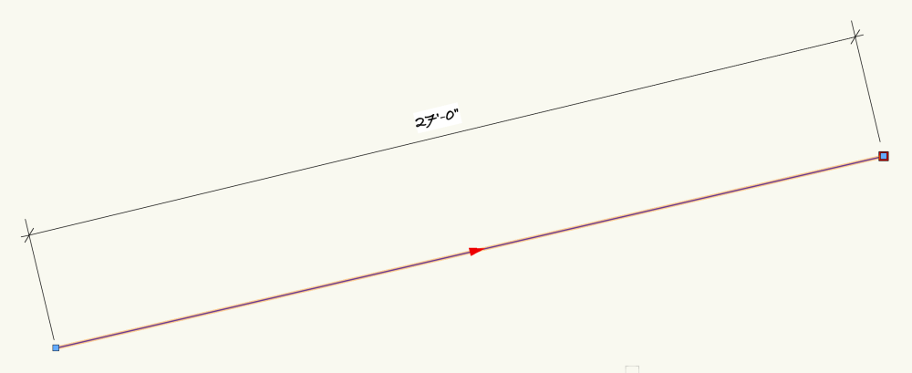
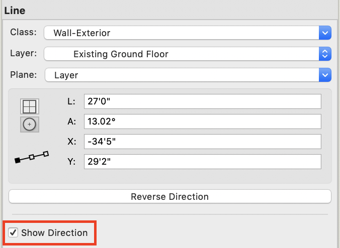
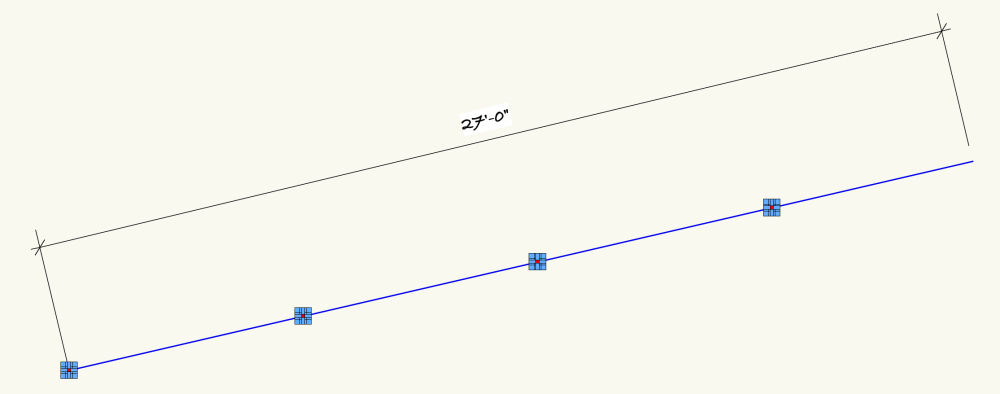
I think you are placing your object at the End of the line - probably as there is 6' remaining?. DAP duplicates as instructed - the original is then 'lost'. The Original can be some way off from the Path, but I guess you want that extra object for your final layout. Chose 'Show Direction' in the OIP You can see where the duplications will start... Therefore in Preview, you still see the original. But you can see the original is then 'lost' when you choose OK If you wanted the original to to be kept at the end of the line, copy the object before the DAP process and then Edit > Paste In Place - and there it is! Hope I've interpreted your query correctly. You don't show a signature, but assuming you're on a newer VW than me, my screen grabs/menus may be slightly different to yours.

-
You’re not giving much background to this as it seems you don’t make any changes to the imported file 🫤. Why didn’t you import a pdf in the first place….can you provide a better series of actions please. (and a signature/os/version will help responses)
-
 The beast is risen - Looking to see how this turns out. So pleased that you’ve grabbed this and are looking at the options (we should all be doing that). I also use a variation of the 2d (top/plan view) and 3d (wall elevation/height) hybrid symbol for domestic switches/lighting/appliances. Go, go @line-weight
 -
Print to PDF giving me a file that is not quite in scale
Gadzooks replied to Christopher Mason's question in Troubleshooting
Good to know your output seems ok. Looks like the final print/plotting side is suspect then. As you thought. Maybe try my earlier option on plotting out your basic scale bars so you can check over a wider area? Can anyone else suggest a better/more thorough check ??? (Hang on Chris - we’ll get you there) -
Print to PDF giving me a file that is not quite in scale
Gadzooks replied to Christopher Mason's question in Troubleshooting
Are you certain of this fact? Or maybe just using a scale rule on the printout? Print techs should know their machines and also the options and difficulties of the software typically used on campus - but it could be worth you asking for a test print of a pdf with just a plain set of scale bars in H & V to be sure? Make them full length/width. The last thing you want is this problem to persist (stating the *** obvious!) You're assuming your pdf is accurate? Although you don't say you have checked your own output by printing the pdf. The file you ask to be plotted may itself be the weakest link. You could import your pdf back into VW to check the accuracy. Hope you get to the bottom of this - I've had my share of printers/plotters with 'sensitive' drivers, both the software sort and the tech sort 😂 -
Start to drag and tab into the options.. Is this what you need?

-
^ What Mr Shorter says. I suggest your aim should be to agree the basic elements of 'transfer/process' before you even start the project. Don't make any assumptions that you will match expectations back/forth - have it in writing (BIM Manual or similar to outline application) if a contract depends on it. You'll then iron-out the pitfalls. You can always swop simple files back and forth before you dive into the details. You'll find various posts here that have the 'drawing' working fine but stumble over incompatible font choice(s).
-
Your signature says 'Windows 7, Vectorworks 2018'
-
I think you'll get quicker help by including more info. First thing you could do is use a signature showing your Version and the OS you're working with (or the OS you're working against 😀) If possible upload the file or a test file.
-
Sorry - bit late to the party on this one, but occurred to me that @EAlexander 's suggestion to use symbols could be implemented similarly by using a viewport approach. Ok - nothing is quite like you would ideally want to get from VW atm, but if you had all your 'general' notes on a dedicated layer and then turned them into mini viewports duplicated and placed as many times as you wanted across your sheet layers that would (also) reflect any additional info/changes you later add to them (keeping one eye on the lower crop line so the original info doesn't stray off if added to) it could be a solution for you until the boffins work some magic with Notes? (yawn) Jeff's hi-tech approach can work well with this option as well. You doctor the Notes getting rid (masking parts ) of numbers and anything else not to your liking and even overlaying Bold/Coloured text as headers if that would be preferred. Once you've created a set of 'portable notes' you're pretty much done. Also allows you to add arrows on a sheet by sheet basis using annotations if required. ....Just a thought......
-
Just this wall or others? Are the wall components attributes set to 'Class' and you have that class switched off atm? EDIT Just looked again and you're modelling without walls specifically, but the above may still be the issue??
-
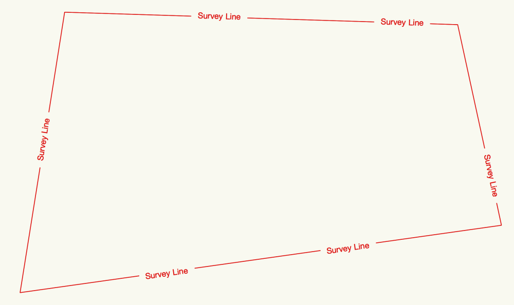
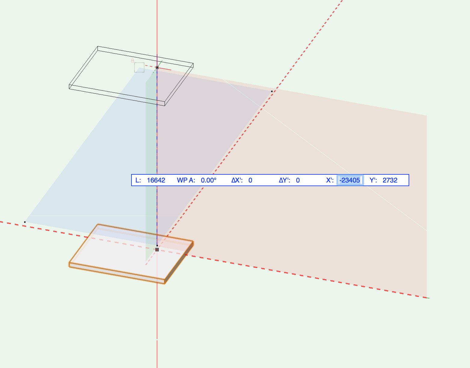
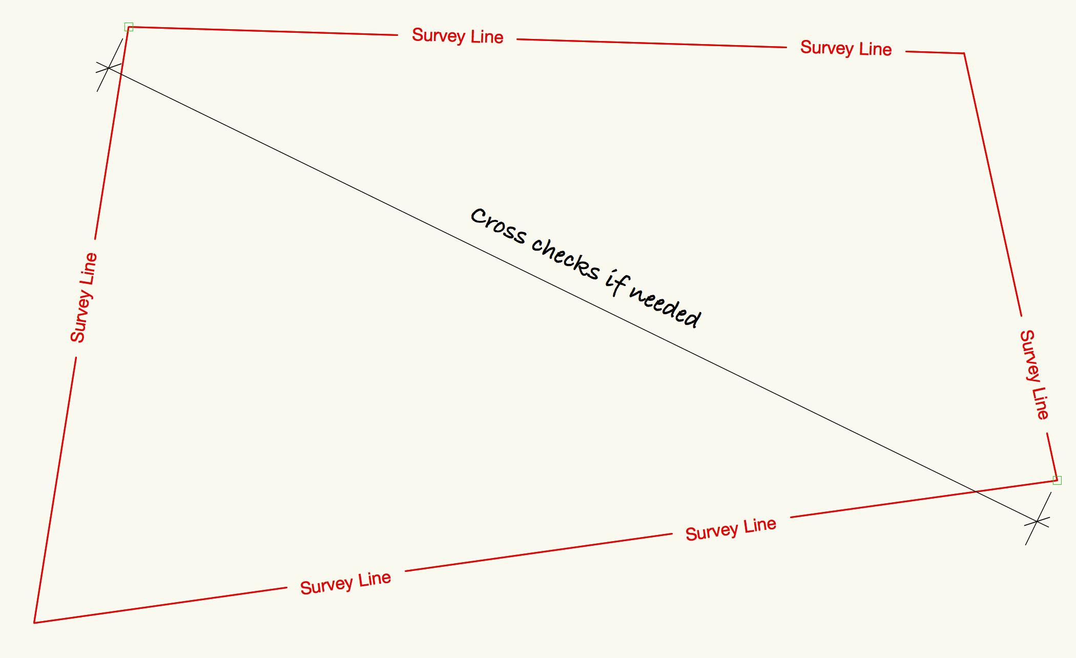
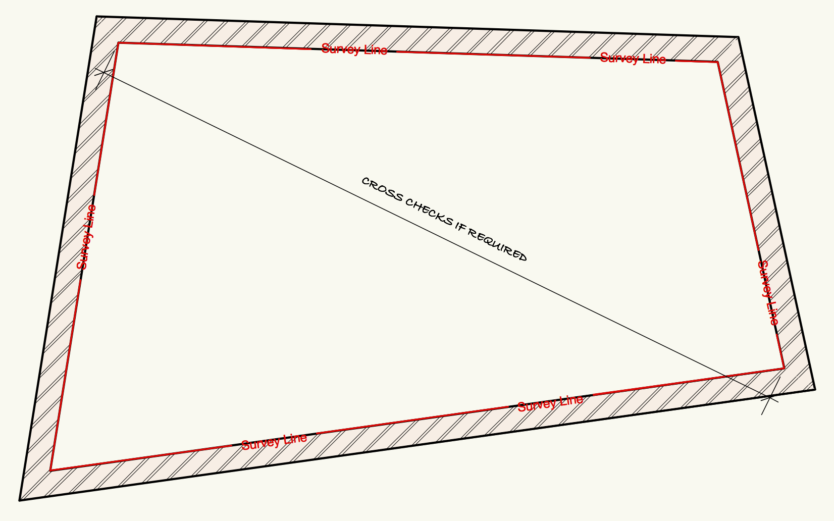
(talking as an 'old-un) Most times it's 'usual' to regard measurements taken on site to be accurate (enough!!) to draw plans from internal notes and assume 90° corners at wall junctions. With a couple of check dims to triangulate a room you can build the existing plans ready for your design changes. There are odd times - I've had basements and cellar spaces - where old layouts have been changed or where a wall may have been built along the edge of a street or actually dives off underneath or over a neighbouring property (Flying freehold in UK), leaving odd walls not built to the expected 90° junctions. That's when it becomes rather tedious to use standard VW walls. If only you could use a plain line rather than a wall!! Using a virtual wall can help... Yes - this is way over the top to show an example. Check dims can be applied and the ends of walls can be moved to meet at junctions way off the 90° expected, but with a far better degree of accuracy. The survey and lines drawn are best taken clockwise to meet the standard VW method. You now have the inner faces in place. Once you have your accurate layout you can then 'replace' with a suitable existing wall type using 'Align right sides'. More about virtual walls here....