


mike m oz
-
Posts
4,885 -
Joined
-
Last visited
Content Type
Profiles
Forums
Events
Articles
Marionette
Store
Everything posted by mike m oz
-
The Subdivision tool (Model menu) is the best way to do this.
-
Wall components not showing up in Section Viewport
mike m oz replied to minotto's topic in Architecture
In Advanced Section Properties you need to change the Attributes settings to Use Attributes of Original Objects.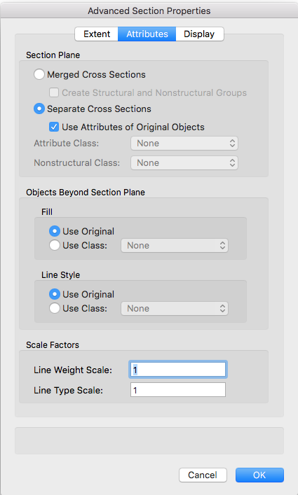
-
Windoor is part of the Australian and New Zealand customisation for that market's versions of Architect, Landmark, Spotlight and Designer. It is not available in Fundamentals or any version of Vectorworks outside of Australia and New Zealand.
-
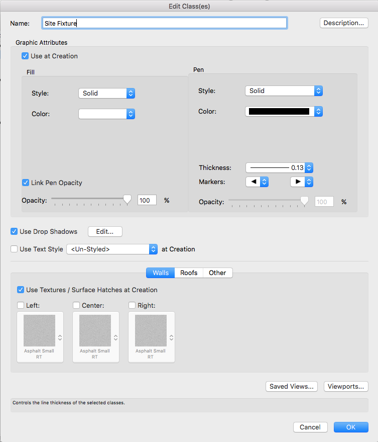
Drop Shadows are applied from the Attributes palette but they can also be defined through a Class definition and be set to be always on or always off if the Use at Creation option is switched on. Your arbitrary switching on and off will almost certainly be related to the Class of the object you are drawing. Even if you have Drop Shadows on in the None Class of the Attribute Palette if your object is a different Class and that Class is set to Use at Creation for its graphic attributes then that will override the settings on the Attributes Palette.

-
Creating a section viewport (Vectorworks Fundamentals 2013)
mike m oz replied to Actintern's question in Troubleshooting
Vectorworks Fundamentals doesn't have Section Viewports. Under the Model menu it has Cut 3D Section and Cut 2D Section. These can be combined together on a Design Layer to create a section like view. These are not live sections though and they will not update as you make further changes. -
The method is the same a in Vw 2016. Select Image from the pop-up. In the subsequent dialog box make sure the option to tile horizontally and vertically is switched on.

-
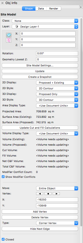
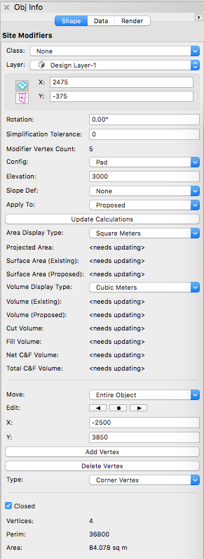
Make sure your: - Site Modifier is a Pad and set to Proposed. - Site Model 2D Display is set to Proposed or Proposed + Existing (depending on which you want). - Site Model 3D Display is set to Proposed. You then need to hit the Update button on the OIP. Don't overlook that you can create Snapshots of the Site Model in different configurations.
-
You could probably do it with the AnimationWorks add on. http://www.ozcad.com.au/products/animationworks.php It would take a long time to render the movie though.
-
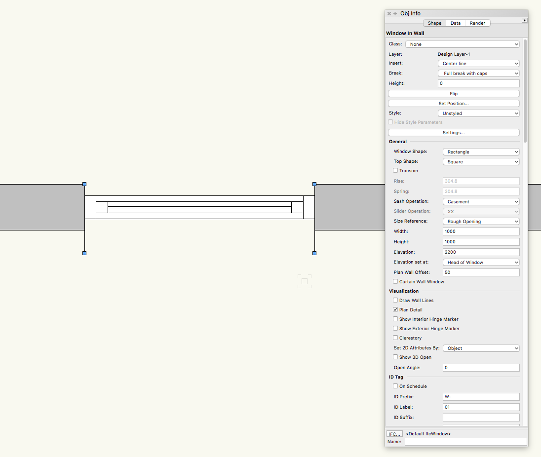
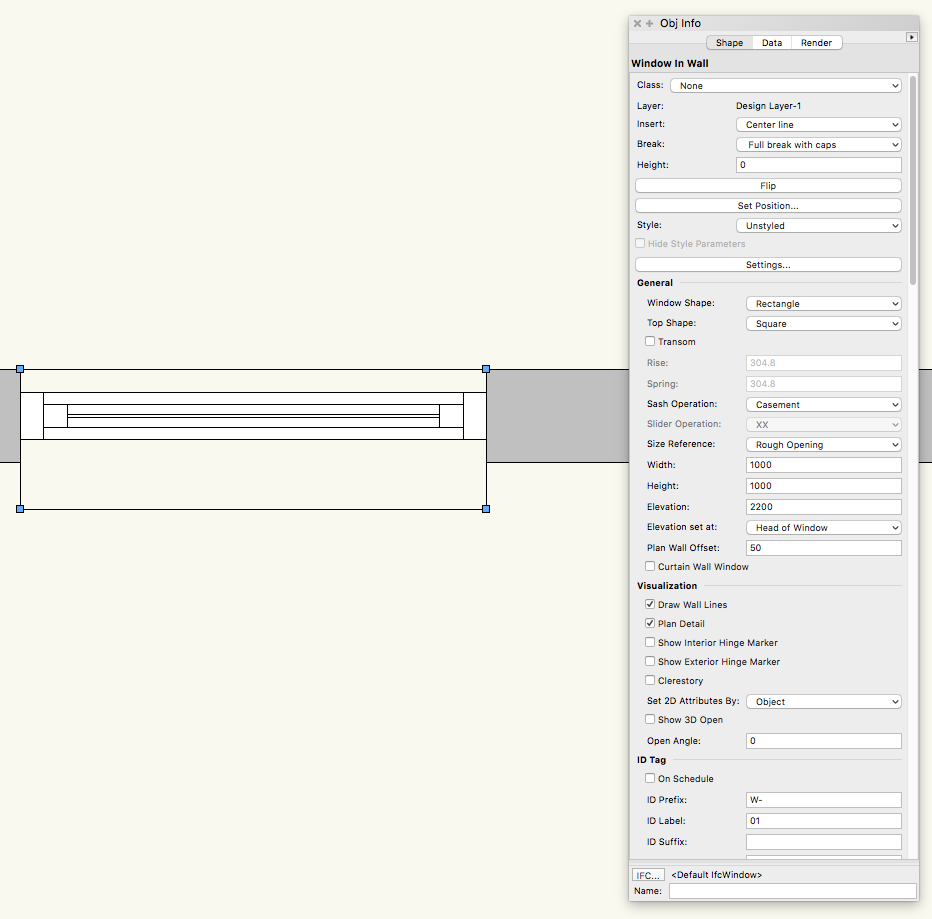
You can adjust the location of the Window in the Wall by adjusting the Plan Wall Offset value on the OIP. Positive values move the window towards the inside and negative values move it towards the outside. That doesn't completely solve the problem though as the Wall break lines show for the full depth of the Walls and if you have Draw Wall Lines on the outer wall line shows where the outer face of the wall would be without the recess.
-
Shelving unit "back" panels have no thickness
mike m oz replied to line-weight's question in Wishlist - Feature and Content Requests
The simplest way around this is to move the shelf unit off the wall by a few mm. Another solution is to turn the shelf unit into a symbol and include your own 3D extrude in the symbol for the back component. I would also like to see the shelf unit made better. Also all the other cabinetwork objects. -
The Vectorworks Design Summits are well worth going to. I thoroughly enjoyed the one I went to last year.
-
Structural Member and Framing member steel beam profile not selectable
mike m oz replied to sww1235's question in Troubleshooting
It works for me so I'm wondering if you have an incomplete installation. Get one of your fellow students to check the file. -
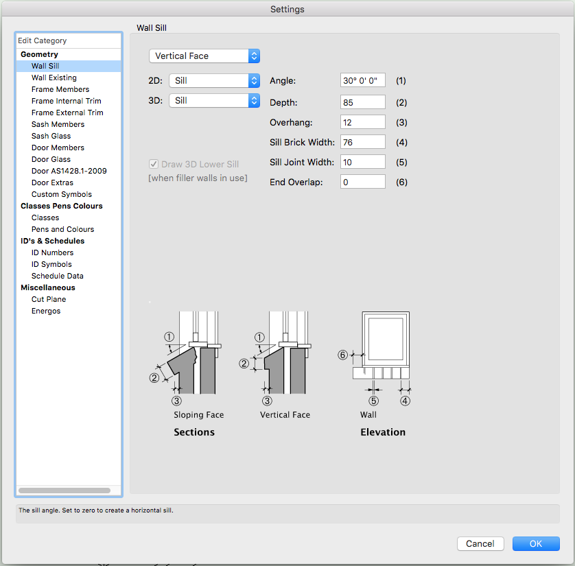
Sharon, on the OIP you have the Set Frame To parameter set to Wall Thickness. Set it to Default Thickness and the masonry sill will appear. Did you really want the window set so it is flush with the outer face of the masonry wall leaf? If so adjust the frame thicknesses in Settings and set the distance from wall face accordingly. Note: Ozcad have confirmed that the behaviour of the masonry sill not activating when the frame is set to wall thickness is intentional. If you think about it that makes sense because you would only use full depth frame in a framed or monolithic construction wall.
-
Use the Deform tool in Bend Solid Mode (Model Toolset).
-
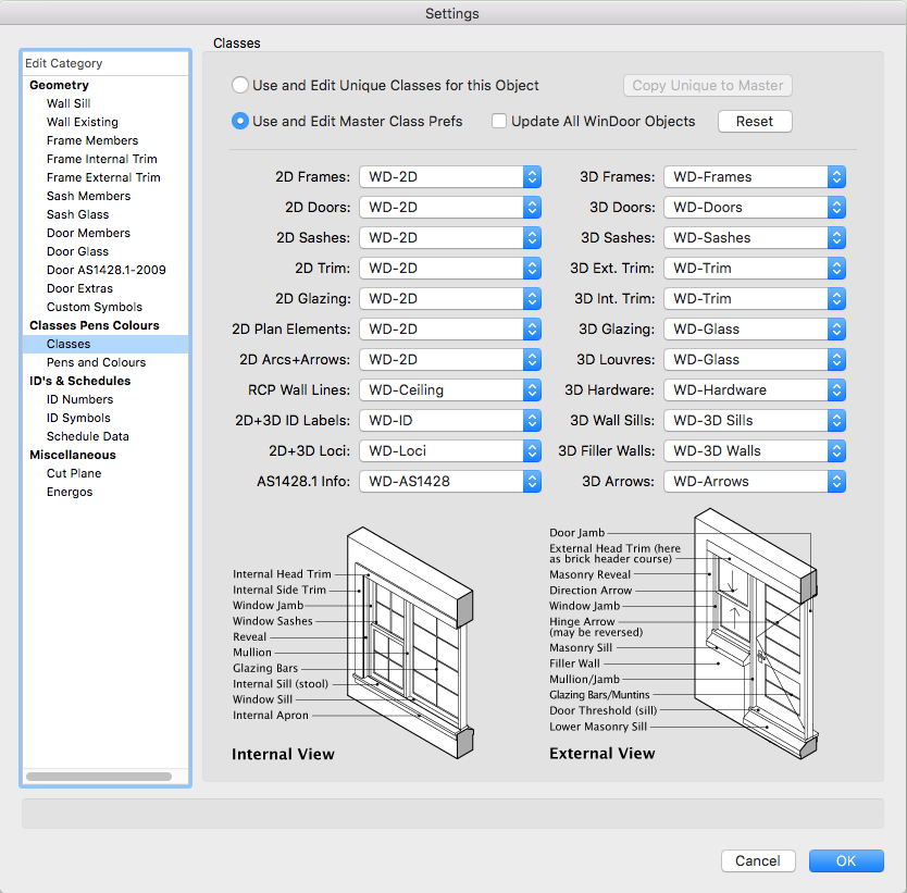
Once you have turned the sill on the Class WD-3D Sill should appear in the Class list.


-
Sharon, can you post a file with just the Wall with the problem Windoor unit in it.
-
Have you checked that: - the Windoor Sill Class is on. - the Windoor unit is not flipped so the sill is on the inside rather than the outside.
-
You need to apply Renderworks Textures to the walls. If there is part of a wall that you want a different colour you can do this with a Decal.
-
On the Render Tab of the OIP change the Map Type to Auto-Align Plane
-
In a blank file try importing the Layers including their content. You will need to reset your bounding heights for Walls and other objects that use bounding. Use the Select Similar tool to select by Wall Type.
-
Screen and Layer Plane - Pain Points and Wishes
mike m oz replied to PVA - Admin's question in Known Issues
Changing the plane type of Screen Plane and Layer Plane objects would be improved by being able to change the Plane type for a Group on the Object Info Palette. Currently you have to enter the Group to make the changes and if there are lots of Groups and / or nested Groups this can be tedious. We also need menu commands to change the plane type of all 2D objects in a drawing (excluding those in symbols of course). -
Windoor is made for the context and protocols of Australian and New Zealand doors and windows. Thus it may not cater properly for other country contexts and protocols.
-
Have you tried changing the display resolution for your screen. Everything will then get smaller and you should then be able to see the complete dialog box window.
-
How do you get text to follow a curved walls?
mike m oz replied to TheSleepyArchitect's question in Troubleshooting
Two other methods that use just text: 1. Use the Text Along Path menu command 2. Use a Decal Texture. You will need to create an image of the text first and then use that image to create a texture. This can then be applied to the textured Curved Wall as a decal through the Render tab of the Object Info Palette. -
Sudden loss of Select Similar Tool, early April 2017
mike m oz replied to jed's question in Troubleshooting
Jed, check which Workspace you have selected because the one in your image looks like it is either the Fundamentals Workspace or one that has been migrated from an earlier version. You can change the Workspace through the Tools / Workspaces menu.
