mike m oz
-
Posts
4,878 -
Joined
-
Last visited
Content Type
Profiles
Forums
Events
Articles
Marionette
Store
Everything posted by mike m oz
-
No, that is not possible.
-
In your User Folder there is a Libraries folder. Within that there is a Defaults folder containing a folder named Door - Custom Leaves. Save a file with a unique name that has your custom door leaf symbol in it. Then place that file in that folder called Door - Custom Leaves. You can access your User Folder from the User Folders tab of Vectorworks Preferences.
-
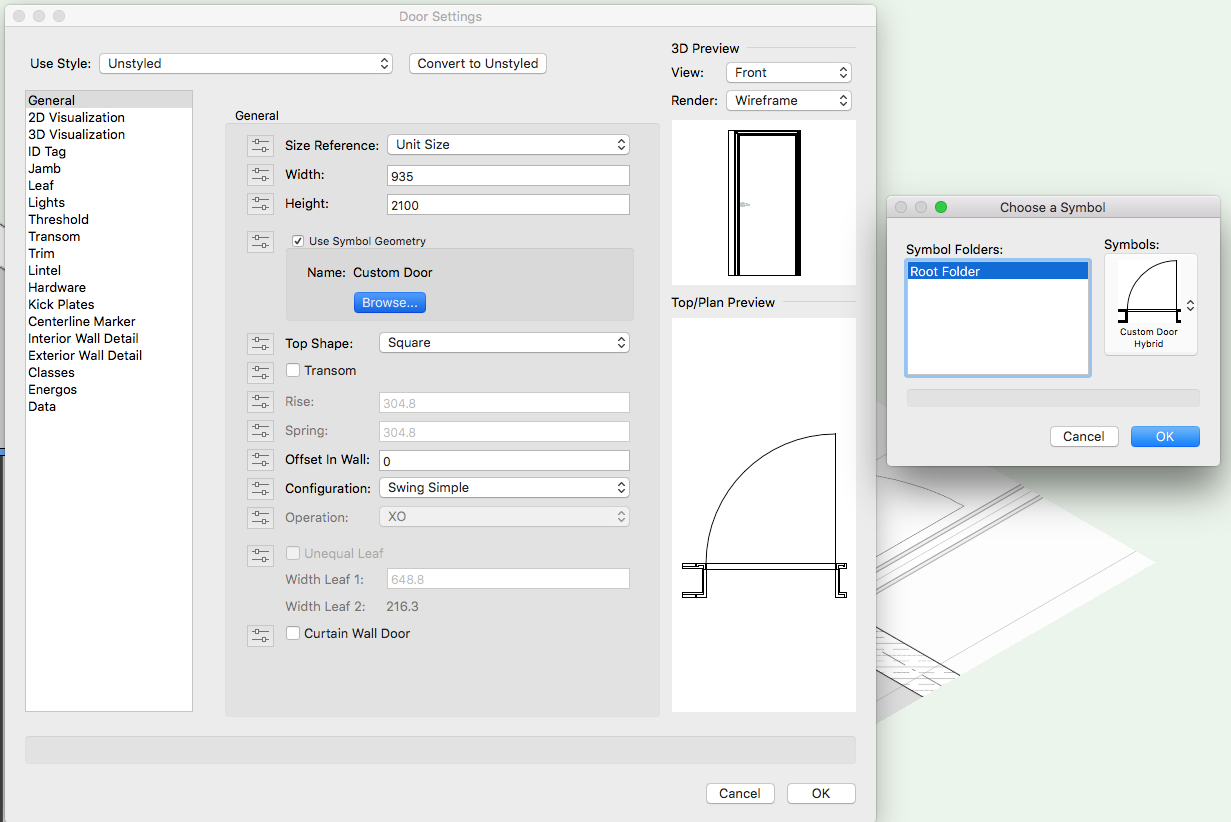
Once you have a Door Hybrid Symbol you can either use it as a symbol inserted into a wall or you can use it within the Door object by selecting the Use Symbol Geometry option. Custom Door Example.vwx

-
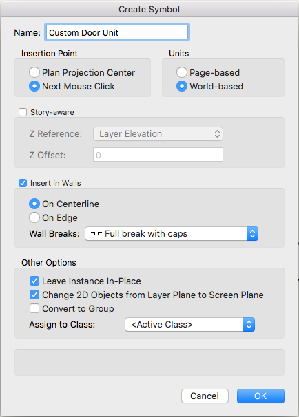
RamiahL you need to make your own Hybrid Symbol for that door: - Model the door in 3D using unique Classes to control the graphic appearance of the components. - In Top/Plan view draw the required 2D appearance in Screen Plane objects on top of the 3D, once again using unique Classes to control the graphic appearance of the parts. - Select both the 2D and the 3D and create a Symbol of them by choosing Create Symbol on the Modify menu. (use the settings in the image below. - The bullseye target marker that comes up will make the insertion point where you next click so choose carefully so that the frame is where you want it relative to the centreline of the wall. I would make it the midpoint between the left frame extremity and the right frame extremity so if you use Flip on the OIP the symbol doesn't move in the wall.
-
trouble with levels/stories and 3d views
mike m oz replied to danbates's topic in General Discussion
Do you have Unified View turned on? (The icon just to the left of the View pop-up on the View Bar). -
Export to DXF/DWG and Export to PDF are both in the Export command in the File menu. You can also choose them as options when you use the Publish command on the File menu.

-
Detail Callout Auto-Coordination and sheet number
mike m oz replied to Josie B's topic in General Discussion
I doubt it will change. -
The existing Push Pull capability (Model toolset) does the extrude mode like bcd's 1d Push Pull mode shows.
-
Detail Callout Auto-Coordination and sheet number
mike m oz replied to Josie B's topic in General Discussion
Alan, this has previously been discussion and the answer is that they don't do two way referencing in the USA. They rely on the builder seeing the detail referencing on the plans, elevations, sections, etc. and going to the detail that is being referred to. There is some sense in that. Especially when a detail applies to multiple locations within the project. -
A 2d Push Pull mode like you show would be a very useful addition to the existing 1d Push Pull mode that you show. Can you illustrate what you mean by 3d Push Pull mode.
-
Move by Points Tool
mike m oz replied to zoomer's question in Wishlist - Feature and Content Requests
This is absolutely needed. -
There is a definite need for the continuing copy mode for the Move by Points tool that you have expressed. It is an obvious improvement and it would definitely get a thumbs up from me.
-
Zoomer, post your suggestions for improvement for each tool in the Wishlist section. There is a greater chance of it being seen and acted on if you post a convincing case for the change in that forum.
-
Try the Vectorbits Vector Move tool: http://www.vectorbits.org/blog/?portfolio=vector-move
-
Stu, look at the end of this Vw video. It shows how to do a fence that follows a sloped site.
-
Can import dwg. to Vectorworks 2017 but can't edit
mike m oz replied to clare weeks's question in Troubleshooting
Open a new drawing and then use the Import Single DXF/DWG command (File/Import... menu) to import the DWG into that file. -
Can import dwg. to Vectorworks 2017 but can't edit
mike m oz replied to clare weeks's question in Troubleshooting
In the top LH corner above Class there will be some text in bold which says what type of object it is when it is selected. A successfully imported DWG will have a Design Layer which is the name of the DWG you have imported. -
Can import dwg. to Vectorworks 2017 but can't edit
mike m oz replied to clare weeks's question in Troubleshooting
On the OIP what type of object does it say the selected objects are? -
https://www.youtube.com/watch?v=hEm5qnAWU44
-
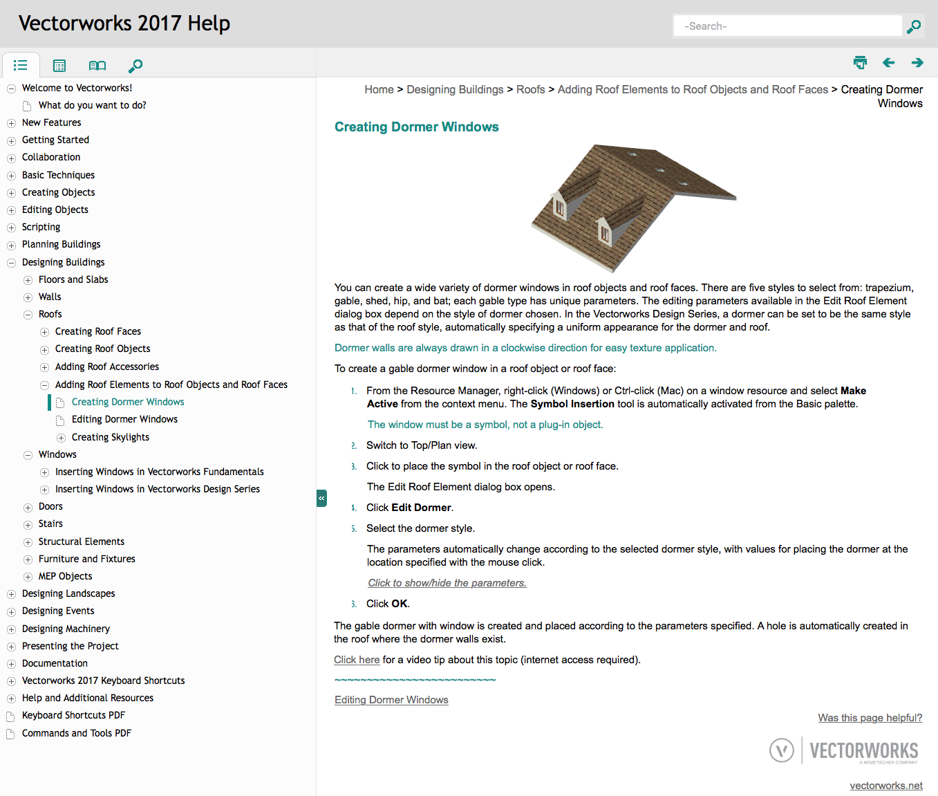
Have a look at the Help section on Dormer Windows

-
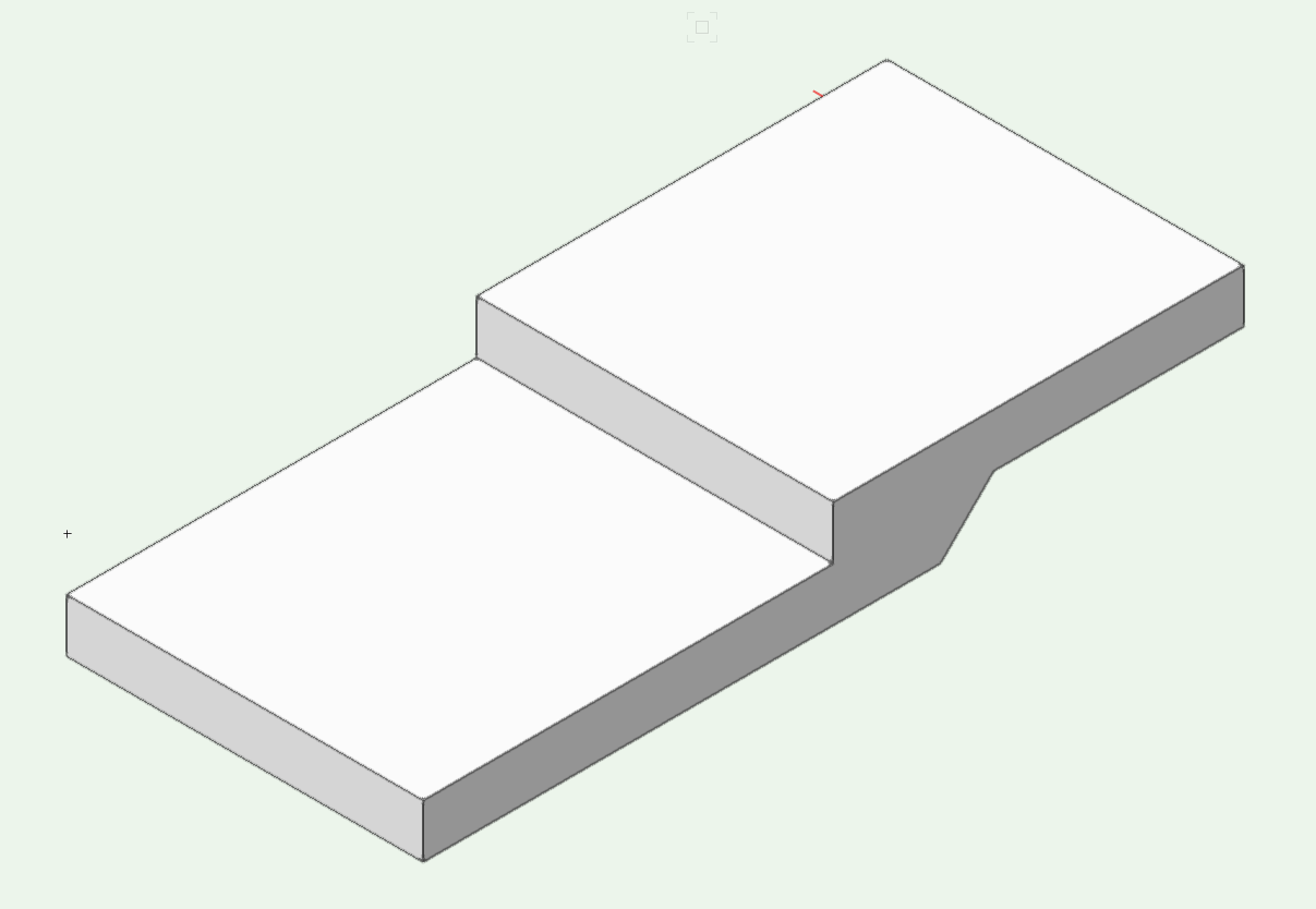
A better way to do this would be to use a Slab object with modifiers for the intermediate landing and then use two separate stair objects. The image below is a 300 deep slab that has had two 150 deep 3D objects subtracted from it using the Subtract 3D Object From Slab command on the AEC menu. Note you need to do this in one operation so select the Slab and all modifying objects and then use the Command. Stair Landing.vwx
-
The Stair object is from Germany. From the message which comes up it would seem they have a limit on flights being a minimum of two treads / three risers. The Custom Stair object may be better option (you might need to add it to your workspace). Alternatively you could model your stair in 3D, then draw the 2D appearance over the top of it in Plan View and then create a hybrid symbol.
-
This is an essential need so model derived Sections and Details can be correct. We need to be able to have the required appearance in 2D and 3D on all four sides of an opening. We also need to be able to have different behaviours on each jamb for contexts where the building condition is different on each side. For example when Door and Window units are ganged together or when one side of a Door or Window unit is adjacent to an internal corner or a projecting pillar. A more complex need that also needs to be solved is the treatment around the edges of non rectangular openings like 'L' shapes and circular/polygonal openings.
- 25 replies
-
- 3
-

-
- window tool
- window reveals
- (and 3 more)
-
Jim it is a two way street and we greatly appreciate your contributions as well. I've certainly learnt heaps from both the moderators and other users during my time on the Board.
-
There are quite a few Youtube movies on Subdivision modelling, including a series by Vectorworks Inc. This is the link to Part 1 of the series: https://www.youtube.com/watch?v=-OmQqkE9Bxs