


line-weight
-
Posts
3,755 -
Joined
-
Last visited
Content Type
Profiles
Forums
Events
Articles
Marionette
Store
Everything posted by line-weight
-
 Is a retaining edge 'pad' with steps in level at the bottom possible? As this sort of thing is often what's actually required in real life. For example with trench/strip foundations, and/or a building that steps in levels down a site.
 -
You could try a horizontal section but that will probably cause different problems for you. The site model doesn't deal with this kind of scenario very well... as it looks like you've already found out, it doesn't want you to make a hole with vertical sides so you get a gap between the building and the 'ground'. I would probably just draw the site manually in annotations and only use the site model for overview type drawings.
-
Additional Roof Options
line-weight replied to Kevin K's question in Wishlist - Feature and Content Requests
This is very similar to how I do stuff. The roof/roof face tools are only really useful at very early stages when you are not showing much detail at all. So, I either draw roofs manually, or I might use a 'roof face' object as the outer layer only. As you say, just like the window and door tools, the roof tool has very little understanding of how things are actually put together in reality. -
Paste-in-place fails (imported file)
line-weight replied to line-weight's question in Troubleshooting
Not quite clear what you mean here - isn't that a line drawn from somewhere off towards the horizon, along the horizontal layer plane, rather than straight down? -
Paste-in-place fails (imported file)
line-weight replied to line-weight's question in Troubleshooting
Because I've moved to an M1 mac, VW2018 is a little bit glitchy for me now and I have fully switched to VW2021 - however, I have opened the original file in VW2018, and tried the same paste-in-place test, and the same thing happens (the wall element re-appears below where it should be). I'm fairly sure I haven't changed the user origin or georeference at any point. I'm a bit worried that you say it has serious problems. While I could copy on a layer by layer basis into a new file, this would presumably lose all of my sheet layers & viewports that I have got set up. -
Paste-in-place fails (imported file)
line-weight replied to line-weight's question in Troubleshooting
The vertical shift seems to be equal to the layer elevation of the layer that was above this one, in the original file. -
Enable Cut Plan at Layer Elevation greyed out.
line-weight replied to Stéphane's topic in General Discussion
I'm not sure why they would not work for buildings on a slope? Is it because you want to show eg. ground floor for each building, but each building has its ground floor at a different level? In that case, I might try and use several viewports laid beside each other but I can see that might get complicated. For me, I find it very difficult to get 'proper' (graphically speaking) plans using top-plan. I expect which method is best depends on what kind of buildings you are dealing with. If they are quite rectilinear with multiple storeys then maybe top/plan works OK. But for example, as soon as I have rooms inside pitched roofs, or anything where I've had to model a lot of stuff manually from solids (old buildings with funny stairs, say) top/plan becomes pretty much useless to me. -
Paste-in-place fails (imported file)
line-weight replied to line-weight's question in Troubleshooting
I don't think it's upside down because the top offset is relative to the layer wall height (2535), and the bottom offset is relative to the layer elevation (0). That said, where the wall is actually sitting (upon import) doesn't seem to bear relation to these levels, whereas the pasted-in-place version is. The location on import is correct as in, that's where it was in the VW2018 file. So I think there's some kind of bug here. -
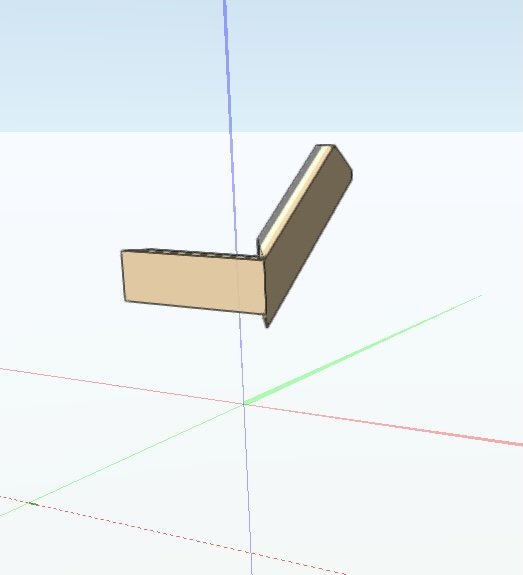
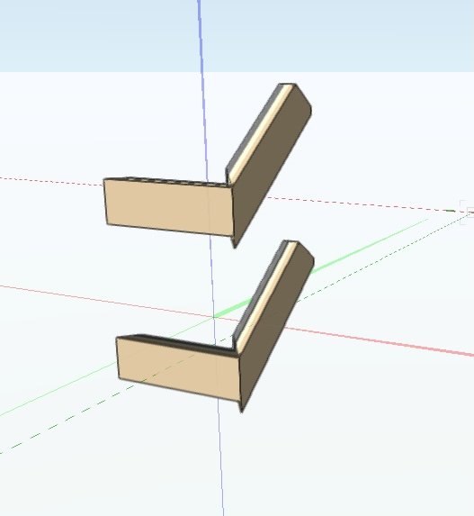
Attached is a stripped out version of a file that I imported from VW2018 to VW2021. 1. Open file, you should see these two objects: 2. Select both objects, and copy 3. Paste-in-place, and I get this: The pasted objects are in a different location, below the originals. All the details in the OIP seem to match. Also, if I paste-in-place these objects into a new empty file, they lose all of their height/peaks info. importedfrom 2018.vwx
-
What specifications software systems are you using?
line-weight replied to LDraminski's topic in Architecture
Can you explain what that is, exactly, and where I'd find more info, please? (Googling SRS system from RLB doesn't seem to get me anywhere) -
What specifications software systems are you using?
line-weight replied to LDraminski's topic in Architecture
It so happens that I just came of the phone with an NBS salesperson before seeing this thread! Same as others have said, I (in UK) would try out NBS chorus if it were less expensive. It doesn't feel worth it, if I might only need to spec up a couple of projects a year. Therefore I do it 'manually' (and like many people I hate writing specs). Often for small projects it's effectively all contained in notes on the drawing. There are various ways in which the notes manager could be improved for co-ordination with specs. If there were something within VW that would let me create a specification document, and then connect this directly to the notes on drawings, and know that both stayed in sync with each other, I'd likely use it. -
Enable Cut Plan at Layer Elevation greyed out.
line-weight replied to Stéphane's topic in General Discussion
That thread I started back in 2016... and at some point between then and now (2019?) VW have introduced the "horizontal section" viewport which is kind-of something similar to what I am asking for there. Essentially a horizontal section is a genuine horizontal slice through the whole model, with a few 2d symbols automatically placed for things like doors, a kind of hybrid between top/plan and a 'dumb' horizontal section (which simply slices the geometry and doesn't attempt to draw things like door swings). For a while I've been using 'dumb' horizontal sections, and then touching them up in annotation space. I've relatively recently moved from VW2018 to 2021 and have only just started out trying to use the 'new' horizontal section viewports. So far I have found that various things don't work properly (although I need to test it out more) but at least it seems to be going in the right direction. In my opinion top/plan is no good for producing proper drawings, and the issues highlighted by this thread are an example of why. -
Enable Cut Plan at Layer Elevation greyed out.
line-weight replied to Stéphane's topic in General Discussion
...and now I understand what you mean about wanting to over-ride it in a viewport. Yes I can see how that might make sense. But I think it is not really designed to be used in this way. It's not really intended that you have several design layers that sit above/below each other, visible in a top/plan viewport. To be honest I think top/plan as a concept is dead (except for editing purposes in the design space) and that's why I am now investing my effort in making horizontal sections work in an "as least badly as possible" way instead. -
Enable Cut Plan at Layer Elevation greyed out.
line-weight replied to Stéphane's topic in General Discussion
Ah - I had not actually noticed before that it is possible in the "design space" per layer - but I see that it is. I've just tried it out... but it doesn't seem to really work as I'd expected. For example if I set it higher than a wall, it shows that wall in 'top' view but it still shows door and window openings cut out of it, which is not correct. I have not really investigated 'cut plane elevation' much so far. My understanding was that it was something that applied to a horizontal section viewport (and therefore affected all layers visible in that viewport, depending on their elevation relative to it). -
Enable Cut Plan at Layer Elevation greyed out.
line-weight replied to Stéphane's topic in General Discussion
I think basically you want everything on your basement layer to be viewed as a "top" view rather than top/plan view - is that right? I don't think a top/plan viewport is able to do this, and it's one of the reasons I don't really use them, and use a horizontal section instead (which has its own, different issues). A workaround I used previously was to have two viewports on top of each other - one would only have the ground floor, with cut plane in top/plan view, and the other one would be a horizontal section, with the cut plane at the same height and with the basement layer visible. I would have to crop around the edges of the "top/plan" viewport which was very fiddly. -
That's true! Let's wait and see what % of the scheduled items make it into VW2022.
-
Any way to control columns in keynote legend?
line-weight replied to KrisM's topic in General Discussion
I've come up against this in the past, and just had to live with it (ie, columns of unequal height). It puts the same number of items in each column, rather than trying to even out the overall column height. Sometimes messing with the number of columns can make it less bad, and sometimes I resort to a trial and error type approach. It's not ideal. (below is a screenshot of a drawing as issued)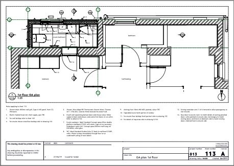
-
The problem with the roadmap is that (as far as I can see) it doesn't commit anything to a specific timescale, so we have no idea whether things shown on it will appear in 1, 5 or 10 years' time. A map with no scale.
-
Sort-of good news but I suppose this suggests that there will be no progress on the regular doors/windows/walls tools in VW2022.
-
Extrude along path not working 'as expected'
line-weight replied to hollister design Studio's topic in General Discussion
And sorry - but if VW [management] chooses not to resource staff sufficiently to read the threads that are posted on here - then yes they absolutely are choosing to ignore problems that are raised. -
Extrude along path not working 'as expected'
line-weight replied to hollister design Studio's topic in General Discussion
I don't doubt that - the failure is in getting issues that are repeatedly mentioned in these forums passed on to the people who can do something about them. We used to have JimW on here who would make sure that happened. When he left, multiple people requested that someone replaced his role (regardless of whether his role was formalised or just someone going beyond the call of duty) and this was ignored and has not happened. I'm fed up with being told to submit bug reports when I've already spent my own time explaining problems here - the process is tedious, time consuming, and puts all the work on the paying end user, instead of the company providing the defective product. -
Vectorworks User Interface Overhaul
line-weight replied to Thomas Wagensommerer's question in Wishlist - Feature and Content Requests
Well - developer of Windoor is now part of global entity that is Vectorworks. https://blog.vectorworks.net/vectorworks-acquires-longtime-distributor-ozcad -
Extrude along path not working 'as expected'
line-weight replied to hollister design Studio's topic in General Discussion
Thing is, in this case, the missing info documentation has been highlighted to VW multiple times since at least 2017, and they choose simply to ignore it. Someone at VW spending a few of hours adding some info to the relevant section would save countless hours/days of frustration on the part of many many users. They don't have to reprint a manual - it's online, and the lack of info persists through each new release of VW. -
Extrude along path not working 'as expected'
line-weight replied to hollister design Studio's topic in General Discussion
Note that this very simple and important fact is not mentioned at all on the help page: https://app-help.vectorworks.net/2021/eng/VW2021_Guide/Shapes2/Extrude_along_path.htm I think this alone is responsible for much of the confusion. -
Thanks, yes, I think I understand this in principle. I realise that other people's monitors will vary enormously - and that it's impossible to guarantee they will see the same thing as I do - but I suppose my thinking is that the closer my monitor is to "correct" then the better chance of them seeing something to what I intend, because otherwise there is colour skewing going on twice - once at my end and then again at their end. Maybe this thinking doesn't actually make any sense? My work doesn't generally involve sending stuff to printers, so that's not such a big concern for me. I do however occasionally print things out on my own printer, and for obvious reasons it's best if what comes out of the printer is as similar as possible to what I see on screen. So, again, it seems to me that the closer my screen is to "correct" the best chance of this happening. But again, maybe that's not the case. From my previous dabblings in trying to understand colour calibration, I realise it's all rather complex. I did do something a couple of years ago that involved printing a design onto fabric, to match some existing dyed fabric; I knew this wasn't going to be easy but it turned out to be much more difficult than I assumed. In the end the only way of matching colours was to look at physical samples the printers gave me - and it also became apparent that it was effectively impossible to match some of the colours, using their printer - they simply were outside of its colourspace.
