line-weight
-
Posts
3,754 -
Joined
-
Last visited
Content Type
Profiles
Forums
Events
Articles
Marionette
Store
Everything posted by line-weight
-
@Matt Panzer is there any prospect in the near future of the "extents above cut plane" being made to work the same as "extents below cut plane" - that is, where I don't have to define/over-ride it for every single class, as described in my previous posts on this thread? I think I remember discussing this more with a focus on the scenario where you might want to show overhead geometry in dashed lines, on a regular HSVP floor plan - but particularly in the case of generating reflected ceiling plans, changing this would make a big difference in how painful it is.
-
That sounds interesting. How would that over-ride work? If I could draw a poly and say "drop the cut plane elevation by 300mm in this area" that would be very useful. Don't think I was aware of this. Will have to try it. But an over-ride applying per region would be more useful than per object I think.
-
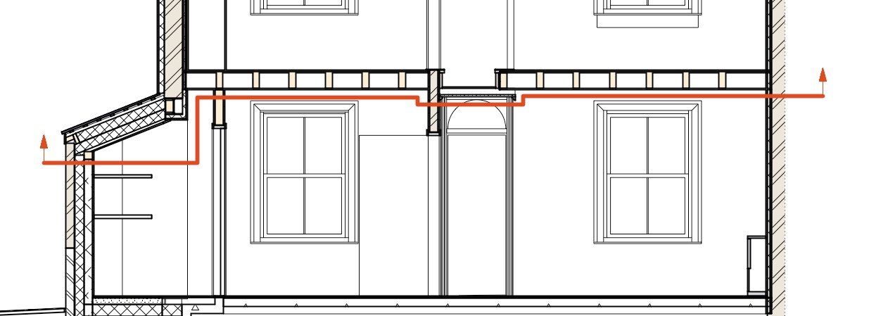
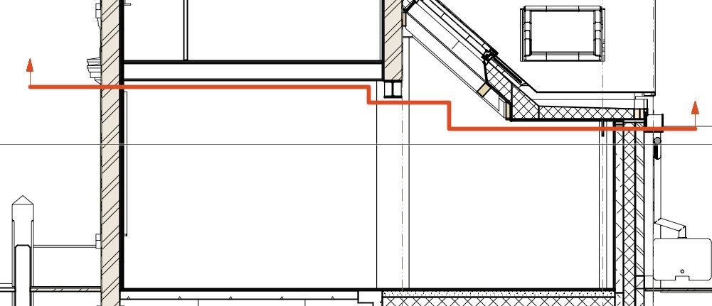
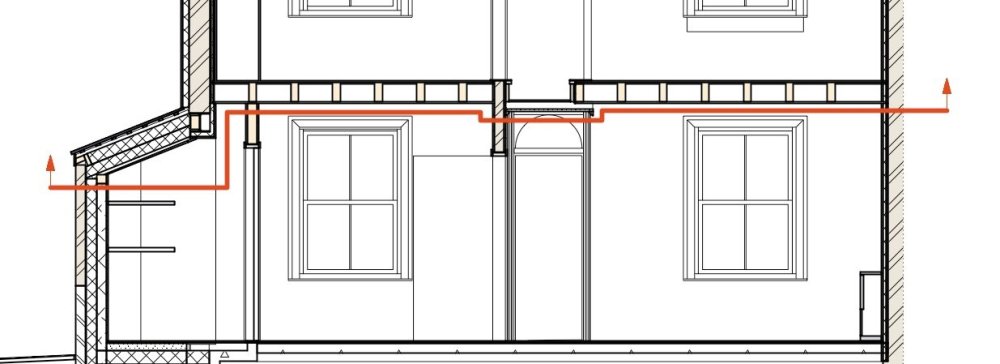
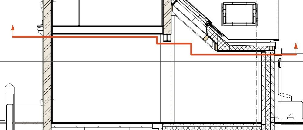
Eurghh. Back to fighting with RCPs again. If the problem I describe in the post above can be overcome, then it can perhaps work OK for certain types of buildings. But a lot of the buildings I work on, they have ceiling and floor heights that can be all over the place, and this means that it actually doesn't work very well just to cut a horizontal slice through the building, because then you have to choose what elevation the cut plane is at, and whatever you choose, it's going to end up slicing through stuff you don't want it to, in certain places. Really what you want is a kind of staggered section. For example, this building, here are two sections through the ground floor (at right angles to each other) and the red lines show where I'd ideally have the "section" cut for the Reflected Ceiling Plan. But this just isn't possible using horizontal section viewports. You can do a single (I think no more than a single?) stagger in a regular section viewport (ie a non-HSVP one). So you could cut a section viewport horizontally, and have a step in it ... and then mirror it. But I don't think it'll then give you gridlines for example, and the fact it's mirrored is probably going to cause weird problems. In any case, as illustrated above, you might want multiple steps, in both directions. Other strategies involve a patchwork of carefully cropped HSVPs, each of which can be at a different level. That gets messy too. Starting to wonder whether it's easiest just to take a very basic horizontal section and pretty much draw my Reflected Ceiling Plans manually in the annotation space, in many cases. Perhaps switching "extents above cut plane" on and off temporarily to trace it. I wonder if any other software deals with this better. It's rather tricky to get something that replicates a manually drawn RCP because they tend to involve a certain level of abstraction in practice.
-
Does your 3d viewpoint seem to have any effect (ie. do the cursor cues start working again if you move away from the geometry - this is something I have realised happens)
-
@Gunther Has just been misbehaving for me. I did as you describe and yes, I could check/uncheck boxes. It was misbehaving while I was editing within a group on a design layer. Going to the Tools>Purge command caused something funny to happen - bits of a random sheet layer became visible superimposed on the 3d view of the design layer, and stayed like this when I exited the group. I had to close and re-open the file to get rid of this. All of this may be entirely unrelated to the missing cues issue of course. Regarding the missing cues - again, it seemed to be the case that moving my viewpoint (3d perspective) further away from the geometry let the cues re-appear.
-
Still has to be done manually as far as I'm aware.
-

Hyperlinks in Worksheets
line-weight replied to Taproot's question in Wishlist - Feature and Content Requests
Bump again. It's 2024. We really need to be able to provide weblinks in things like schedules. -
Although that would be useful in the long term, the General Notes object first needs to have the simple option of turning off the list numbering. Until that's possible, being able to style it wouldn't help. ...Unless you meant a style for callout objects? Yes it would be good to style callout objects. At present I "style" callout objects using dedicated classes which lets me set things like arrowheads. But it doesn't control all aspects.
-
Yes, it seems that a neutered callout object is an option. This wouldn't put multiple notes into a tidy list like the general notes object can. (I don't want the asterisks there - they are only there to replace the numbering I don't want, using a method less cumbersome than the type of thing @Jeff Prince describes)
-
I'd not thought of the Title Block as a strategy. Is this going to be able to cope with say 50 different "general notes" that I might want in a variety of combinations depending on the sheet? I think it would also mean I'd have to put the notes in a fixed location that was the same on all sheets. That would mean that I couldn't place a general note in such a way that it applied to only one viewport on a sheet with multiple viewports.
-
In actual fact, for current purposes I don't even necessarily need to pull items from the notes database into a report. It would do just to have a basic manually drawn table, but I would want to drop some text blocks into it (using items from the notes database) that would update in the same way callouts do. But it seems like the only options for doing that are hacky versions of a callout object or general notes object. That is unless there's something I'm missing.
-
Thanks. I guess I am kind of the other way round from you ... I have got myself invested in the notes database approach and don't really want to start mixing up with data tags for similar reasons of graphic consistency (and sticking with what I know already). I think you are quite right that there are (at least) two kinds of notes, ones that are associated with a specific object and ones that are more general, and currently VW doesn't seem to make it easy to deal with both types in the same system. I think actually there are more kinds than that... There are notes that are specific to one object, notes that are specific to a type of object, notes that might apply to multiple objects, notes that are just to do with reading the drawings, and so on. The notes database isn't currently sophisticated enough to cope with all this in a tidy way. I can see why you might want to use record formats because then you can have multiple fields and (presumably) choose which ones you want to be used for a data tag.
-
Well, my workaround above sort-of works but is not great. I'm realising that I'd like to expand this to a more general question, which is whether there is any other reliable way to extract data from the "notes database" other than via a callout object or a general notes object. For example, can I get the info into a worksheet? Say I have a bunch of fixtures & fittings and each has a spec including product reference and so on. The same fitting might appear on multiple drawings - plans, internal elevations and so on, and it's straightforward for me to point to it with a calllout, and have that callout display the spec info pulled from the notes database. And if I change the spec of that fitting, then all the callouts that point to it, on multiple drawing sheets, can update accordingly. But if I then want to make a schedule of fittings, formatted as a table, can I do that with a worksheet where I can pull in the relevant specification text for each fitting? So, if I update the text in the notes database, it'll update across all callouts but also in that table? I seem to recall other threads where I think @Tom W. has said he uses data tags instead of the notes database. Have I reached the point here where I realise the reason for that - or am I missing something basic?
-
@Kristin Bailey thank you for replying on this thread. I've submitted feedback via the "was this page helpful" link a couple of times. On one occasion I got a reply which was great - on the other, I heard nothing back. I don't know if that suggests things don't always get delivered to your team (this was at least a year ago I think). Also, in the thread I linked to above, I made some comments about how the process of leaving feedback about help pages could be made a lot easier - here's a link to the specific post: https://forum.vectorworks.net/index.php?/topic/104945-please-stop-telling-us-to-re-report-problems-via-black-hole-webforms/&do=findComment&comment=458101 I do quite often come across things that I think are missing from, or could be improved, in the help pages but I have to say that much of the time I just don't have the energy to provide the feedback because of: 1) the tedium & time needed to go through that feedback form 2) a lack of confidence that my message will actually get read or acted upon, due to my previous experience of only sometimes getting a response. I'm sure you don't want to encourage so much feedback that you get swamped with it ... but addressing those two factors, I think, would make it more likely that people with constructive comments pass them on to you. As @E|FA 's linked thread above suggests - a proper ticketing system would make a big difference. Just getting a confirmation that something's been submitted, and a way of tracking it, helps give confidence that something is happening even if there's not an immediate reply.
-
See this thread
-
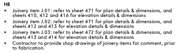
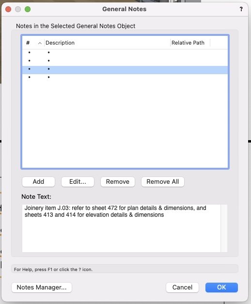
Yes - I guess I could do that. However - the "general note" tool has the following useful abilities: - can pull the text from the notes database - can put multiple notes in a tidy list with a heading, preformatted It's just frustrating that I can't opt out of the numbering/lettering. At the moment I'm trying a workaround where I choose "note description from database" from that dropdown and for all the notes that I want to appear in my general notes list, I make the note description just an asterix. This gives me a general notes list like this: And that's ok (ish) but it makes the notes rather awkward to manage because they can't have meaningful descriptions - I have to select each one in the list of stars to see what text it contains:
-
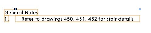
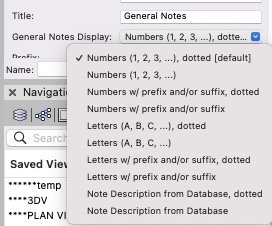
I make fairly wide use of the notes database & callouts, sometimes using keynote legends and sometimes not. This has its many annoyances but basically works for any callout note that I might want to repeat across multiple viewports. I can update the text and it'll update across all instances. But what about more general notes - that is, not attached to a callout and not attached to a particular viewport. For example I often want to put a note on a drawing sheet that says something like "Refer to window schedule on sheet XXX for full window details". I might want to have that note on several drawing sheets, and in the future I might want to change the wording, and have that wording update in all instances. There is the "general notes" tool but it wants to format the notes like this: I don't want that "1." there. In the settings I can choose from this list: But I don't want any of these. It doesn't give me the option to have only the note text. Is there any way around this - a way just to have the note text? (Why don't I want the notes numbered? Firstly because it might cause confusion when there's also a keynote legend on the sheet. Secondly because it uses up page space needlessly. Thirdly because often I'll only want to have one note in that "general notes" object, and it then looks odd if it's numbered.)
-
Saved Views - classes turned off
line-weight replied to James Dawson Design's topic in General Discussion
I don't make as much use of the organisation dialogue as I should. Have just realised now, that this will let me bulk-select multiple saved views and apply changes to them all in one operation.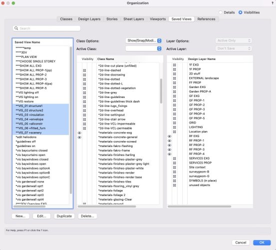
-
Have you made sure that the lights you've created are "on" and are on a layer that's visible?
-
Saved Views - classes turned off
line-weight replied to James Dawson Design's topic in General Discussion
The way I deal with this, is that I rarely create a "new" class, instead duplicating & renaming an existing class which has similar visibilities as I want for the new one. This is hardly an ideal method and I still have to quite often edit saved views settings. If there's a better way of doing it I'd be interested to hear too. Commonly when I make a new class I'll want it to appear in some saved views/viewports but not others, so simply being able to make new classes visible everywhere wouldn't solve the problem. -
Same here. I don't bother with the VW "interior elevation" tool. I just make a regular section. Crop out the bits that aren't needed for the internal elevations. Draw as much as possible in 3D and only add final touches in 2D. The more you draw in 3D, the more automatic updates can be in all viewports, if you change the design. I'd not explode or flatten viewports because then you have to star again if you change anything in the model. The main thing I'm not entirely happy with, using my current method for interior elevations, is that I have to crop them to funny shapes manually. And sometimes the edges of those crops can be a little messy.
-
VW wrongly tells me classes are invisible when in annotation space
line-weight replied to line-weight's question in Troubleshooting
Yes, I see, the same happens for me. Mention of the custom selection command has prompted me to try something that I've not tried before - to see if I can specify that objects of a certain type, within the annotation space of a particular viewport, can be selected. There's a criteria "location" which lets me choose a viewport. When I do this, the chosen objects appear to be "seen" (they are counted in the dialogue box), but as you describe, aren't actually selected when I run the command. And this seems to be the case even with the relevant class turned on in the sheet layer view (as well as in the viewport). -
VW wrongly tells me classes are invisible when in annotation space
line-weight replied to line-weight's question in Troubleshooting
Is this caused by something to do with the data tag objects, or something to do with the "select similar" function, do you think? (I don't really use either so haven't noticed this myself) -
Notes Manager / General Notes / Callouts Suggestions
line-weight replied to _James's question in Wishlist - Feature and Content Requests
People at Vectorworks - are any of you reading this thread? This tool really is a nightmare to use - can you give us any indication that things will improve, or that the problems raised are understood? -
Interesting. It doesn't look like it's specifically designed for 3D navigation though? Would be interesting if you can report back on how you find it.