line-weight
-
Posts
3,755 -
Joined
-
Last visited
Content Type
Profiles
Forums
Events
Articles
Marionette
Store
Everything posted by line-weight
-
Is it just an extruded polyline, or is it an extrude-along-path? If it's just an extruded polyline then you should be able to edit it in-place but if it's an extrude-along-path then it's always a bit of a problem that it is difficult to edit the geometry relative to the "outside world". If it's an extrude-along-path, is it the "path" or the "profile" that you are trying to edit?
-

Display Symbol instead of Layers in Viewport
line-weight replied to Kevin McAllister's question in Wishlist - Feature and Content Requests
Yes, this can be the case even with normal viewports - it would be good if a viewport's crop & annotations could somehow be tied to an element within the geometry it's looking at. -
Display Symbol instead of Layers in Viewport
line-weight replied to Kevin McAllister's question in Wishlist - Feature and Content Requests
This would definitely be useful. Like the OP, I sometimes want to produce drawings that show a symbol isolated from the rest of the model and currently this means setting up special layers or classes in addition to the symbol itself. Plus, the instance of the symbol that the viewports are looking at has to remain at a certain location in space in order for things like crops & annotations not to get messed up. It would be good to have viewports onto a symbol that were relative to the symbol's own internal co-ordinates not those of the outside world. -
Creating a viewport from design layers
line-weight replied to Monique Freese's topic in Architecture
Didn't know that either! -
A Master 2d Detail Library & 3d Model
line-weight replied to digitalcarbon's topic in General Discussion
I can see that the extent to which the person making the drawing is involved in the design (and the overall drawing strategy) is significant. I have the luxury of being a one-person operation. It would be difficult to have a team of people working on my drawings, the way I currently set them up. -
A Master 2d Detail Library & 3d Model
line-weight replied to digitalcarbon's topic in General Discussion
Yeah, the reality is that I to resort to 2d in annotations, for things like membranes and (sometimes but not always) thin sheet materials. I don't have a pure 3d workflow by any means. However... over the course of several projects where I've tried to reduce the 2d content each time, I've found that it's more feasible than you might expect, to try and draw "nearly everything" in 3d. There are of course pros and cons but some of the pros are significant. For example I find it's also very helpful in actually working stuff out design-wise, and highlighting things that aren't going to work. -
Creating a viewport from design layers
line-weight replied to Monique Freese's topic in Architecture
Didn't know that was possible - thanks for the tip. Does that also work for changing the crop, if there's already one present? -
A Master 2d Detail Library & 3d Model
line-weight replied to digitalcarbon's topic in General Discussion
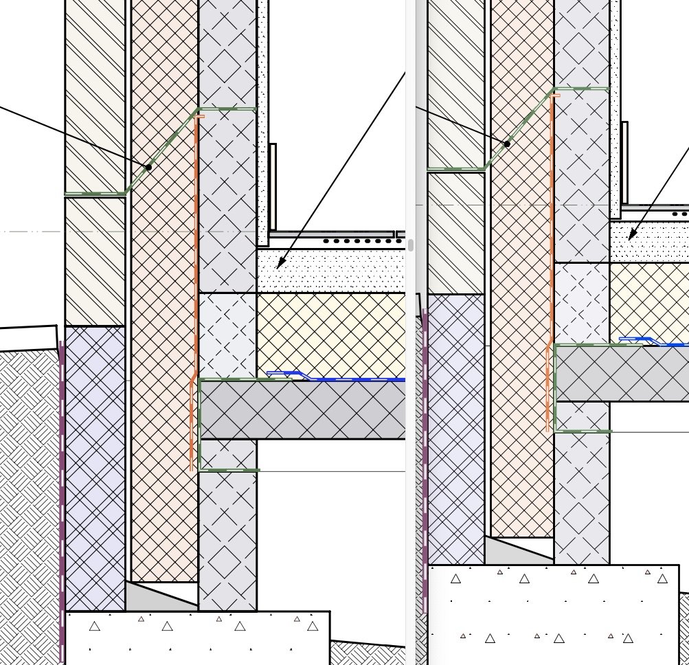
This will be a controversial viewpoint but why mess about with all these 2d details and remain stuck in 2d thinking when you could just draw them in 3d instead (in an intelligent way). All of these details are extracted directly from the 3d model with minimal additions in annotation space. I don't have to model the geometry individually for each window, because of the way I have built the window frames (they all use extrusions of 2d profiles which can be edited in such a way that I can change them all at once) and they also make full use of wall closures. It's possible to set up a model in such a way that you can extract all of your details directly from it - without actually having to draw every single part of the building in full detail. There may be a scale at which this approach starts to break down, but at least for the kind of small projects I do, it works better than you might think.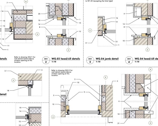
-
Creating a viewport from design layers
line-weight replied to Monique Freese's topic in Architecture
I always crop viewports after the event. Once you've created the viewport on the design layer, you can double-click on it and then choose the option to edit the crop. Or you can right-click and choose "edit crop". Then you can draw whatever shape you like and this will become the crop object. -
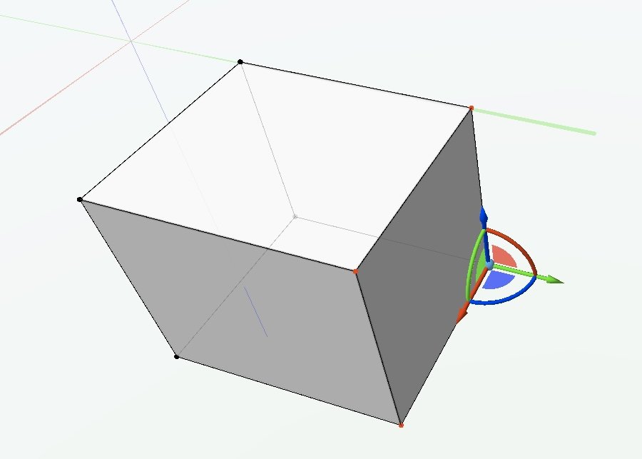
The subdivision tool is mainly intended for freeform modelling but you can also use it for more rectilinear shapes. https://app-help.vectorworks.net/2023/eng/VW2023_Guide/Shapes3/Subdivision_modeling.htm
-
See the original mobius thread (this one is a kind of spin off). I had some success with the subd tool there: https://forum.vectorworks.net/index.php?/topic/104317-modelling-challenge-möbius-strip-model-this-as-a-seamless-solid-with-no-visible-joins/
-
@apswoodwork the issue you describe is a common one. I come up against the same problems modelling windows where i want to be able to change the overall size without distorting the frame profile. In theory the EAP tool lets you do it but frankly it's one of the most horrible tools in vectorworks. Check out plugins like the one jeff prince suggests, to make your life easier. Actually at the moment I'm helping test another similar plugin, that improves on EAP, but it's not been properly released yet. One of the issues with EAPs is that it's very difficult to adjust the "path" geometry relative to surrounding objects. Plus it's just generally prone to failing and not telling you why. Once you get into the swing of doing things in 3d I think you'll find it's better and more satisfying. I made the transition from 2d to 3d a few years ago and wouldn't go back. It can be less work to revise a 3d drawing than a 2d set, because you just adjust the model and then all the plans elevations and sections update themselves (in theory at least). Plus you have the opportunity to visualise the thing in 3d of course, which can sometimes help you to spot things that might be difficult construction-wise in the real world.
-
Yeah a familiar problem and I'd agree with your suggestions! For a beginner ... it's well worth being aware that as soon as you do a push-pull operation on an extrude, you generally lose the option to go back and edit the 2d source shape - I try and keep this in mind and do edits to the 2d source shape rather than push-pulling, if possible; it's a less destructive mode of editing. Occasionally in this scenario, if it's something I know I'll want to pull around a lot, I'll make a subdivision because that allows you to select groups of nodes in a similar way to the 2d reshape too.
-
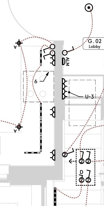
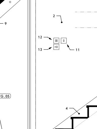
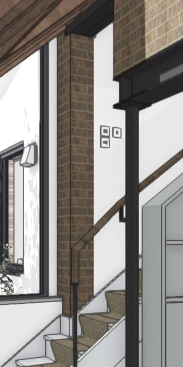
So... I just completed a set of drawings where I used this method. Below, some extracts from the electrical plan, a wall elevation and a 3d view. Pros: It's quite satisfying that once it's all set up, I just place a lightswitch or socket as a 3d object, in the model, and it then appears in wall elevations, and also symbolically on the electrical layout. And it's nice to know that if I want to delete it or move it I only need to do that once - I just move the 3d object and it updates everywhere else. Cons: It takes quite a lot of careful set up and thinking about class visibilities, stacked viewports and so on. Although, it'll be much easier to set up the next time. I'm a little concerned that I might come back to this drawing in a couple of months, needing to make some amendments under time pressure, and have completely forgotten how I set it all up. The main annoyance really is what to do about 2d symbols that land on top of each other because the fittings they relate to are stacked vertically above one another in 3d. It's a bit of pain to have to make variants of symbols, with offset 2d contents, each time you come across this problem. I've wondered whether a solution might be to split the layout into separate lighting & power layouts - then the conflicts would be much reduced. It wouldn't be much extra drawing work, but maybe it would be annoying for contractors/electricians... not sure. A few other small issues, like you can see the downlight symbols have ended up upside down with the "A" the wring way up - presumably physically rotating the 3d container object would sort that.
-
The OP needs to explain more clearly what their question is.
-
I see. I guess I'd assumed the "most recent issue" data would be stored at file level rather than being contained in individual TBBs. Does VW have to look through every TBB in the file to work out what's the latest issue date? Anyway, I think it works fine just to include the drawing register sheet in each issue, because if it displays the latest issue no. and date for that sheet, it ought always to be correct (hopefully...time will tell).
-
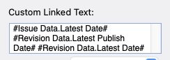
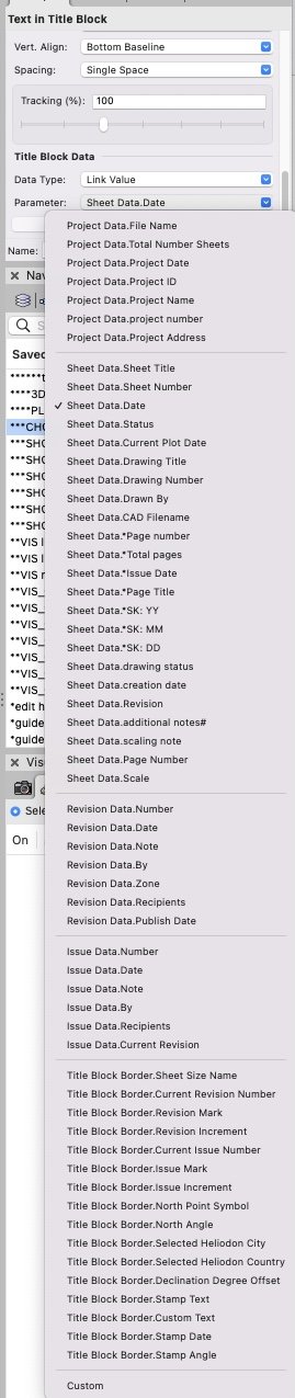
Thanks. I've tried these three The first one pulls through a date, but it's the date that I set as the issue date of the sheet the drawing register's on. I suppose that will work as long as I include the drawing register in each issue I make, but ideally I'd like it to pull the same data that the drawing issue worksheet pulls.
-
PDF Export is darker than on screen colors. How to change?
line-weight replied to JonKoch's topic in General Discussion
Has anyone managed to get anywhere with this? Using the "publish" command results in PDFs with colours that look noticeably different on screen, compared to when they are viewed in Vectorworks. This is a screenshot - on the right is the bit of drawing viewed in VW, on the left is the same drawing exported to PDF. I've overlaid the two application windows, Preview on the left, VW on the right. The colour difference might not look dramatic here but it can with a rendered image.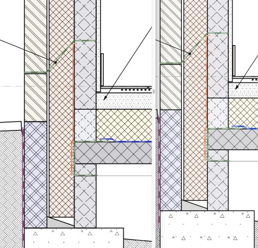
-
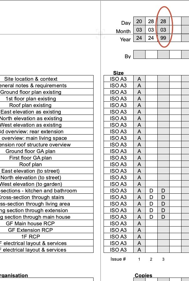
I have a slightly side question: I am making a special title block border for the sheet that I will put my drawing register on. Can I make that title block automatically report the date of the latest drawing issue? Can one of these options for linked text do that? It's the date in the red circle I'm after (this is a sreenshot of the drawing register):
-
Thanks. So it has no "intelligence" about things like orientation of surfaces or distance from camera etc direct from the model ... just what it mysteriously works out from the pixels. (One of the things that surprises me most about these AI image generators is how they manage to get that stuff mostly right - if the light is shining from the side they seem to know what surfaces to light up. I find it a bit spooky really.)
-
Is it that your negative prompt needs to be "red color" rather than "no red color"?
-
At some point, VW started to refuse to render these Rendermall plants when they are on the other side of some glazing. Well, it'll render them while I'm flying around but not when I'm stationary, nor in a static viewport. All I get is the trunks, no foliage. This is all using Shaded mode. Any clues? Screen Recording 2024-03-28 at 19.11.21.mov
-
Does the AI "understand" the 3d geometry of the VW model at all or is it simply looking at a 2d image of it and doing its stuff from there?
-
Editing notes in "general notes" object: "edit" button calls up wrong note
line-weight replied to line-weight's question in Troubleshooting
@jblock did you get a chance to look at this? In the meantime I've been finding another problem: 1. edit a general notes object 2. click on "notes manager" in the general object dialogue 3. in notes manager add a new note, description "A" within chosen database 4. click ok and go back to GN dialogue. 5. add that note "A" to the GN object. 6. go back to notes manager 7. edit the newly created note, changing its description from "A" to "B" 8. back to the GN dialogue and click OK What I expect now to happen, is that the note with description "A" in my general notes object, which was linked to the database, should change so that its description is now "B". But that's not what seems to happen, instead the GN object still has a note with description "A" but it is unlinked from the database. To get the edited version, the version now with description "B" into my general notes object I have to go and re-add it from the database. Maybe I am doing something wrong here but this has been causing me a lot of confusion. -
Adding Scale Bar to a Drawing Label
line-weight replied to Matt Strong's question in Troubleshooting
I want to do this too! Would save a lot of layout time if I could have a scale bar automatically get placed alongside a drawing label, at the correct scale for the viewport. The drawing label knows what scale the viewport is, so surely it must be possible.