Search the Community
Showing results for tags 'tool'.
Found 13 results
-
I had a quick search but I couldn't find anything. Is there a function in Vectorworks Spotlight 2017 that allows me to insert a lighting symbol at different lengths? So the length of the symbol is variable? For instance, when I draw LED tape the length is never a set amount. It is normally set to the size of scenery or buildings. Which means there are sometimes over 10 different lengths the symbol can be. Which makes reports and instrument summaries a nightmare. I think it will be really useful if there was a tool in which you could choose the type of LED Tape (For example RGBW @ 8w per meter). And be able to draw the tape live on the plan. Sort of like how the truss tool works but more of a click and drop like system (So you can create curved tape). It would then be useful for this to automatically be a singular lighting symbol and add information to the `Light Info" records. For example standard lantern information such as Unit Numbers, Circuit Numbers, Purposes, Positions. And additionally new information such as automatic Tape lengths, splits, and final wattages calculated from the watts per meter given and the variable length. I think when it comes to the instrument summary it would be useful if there was just one symbol that showed a section of the length. Named for example RGBW LED Tape. At the moment this is possible but the build list is flooded with 10 different lighting symbols for LED Tape. I know you can choose to hide/show symbols in the build list but symbol management would be so much organised. Let me know if this does or does not exist. Hopefully, I haven't been too oblivious. Many Thanks, Ryan Lawrence
-
I have a code that looks something like this: Get Keyboard input -> get mouse coordinates at click -> place object at position of mouse click and with scale of keyboard input So for example: press 7, click 0,0 --> get object at 0,0 with scale 7. My problem is that tool commands can only really be activated when you click with your mouse. Since the keyboard input happens before the click there would have to be an additional click before the keyboard input which is not optimal because I want the whole thing as efficient as possible. I can of course get the mouse/position input first and the keyboard/scale input second but this would also necessitate an extra step to signify when the keyboard input is complete (which would normally happen through the mouse click). It also wouldn't allow me to run a temptool that shows the appearance/scale of the object before you past it/click. Then there is the option to run all of this in a loop, something like: REPEAT Get Keyboard input get mouse coordinates at click place object UNTIL But this has the problem that, while I am in a loop I can't really use the other functions of the program like zooming in or shifting the screen which makes the whole thing a bit uncomfortable to use. This might be a little bit complicated to get around. Is there any way to activate a tool with a key stroke, or to get access to the normal program functions during a loop? Would be great if anybody knows if that is possible. I can share the whole code if needed.
-
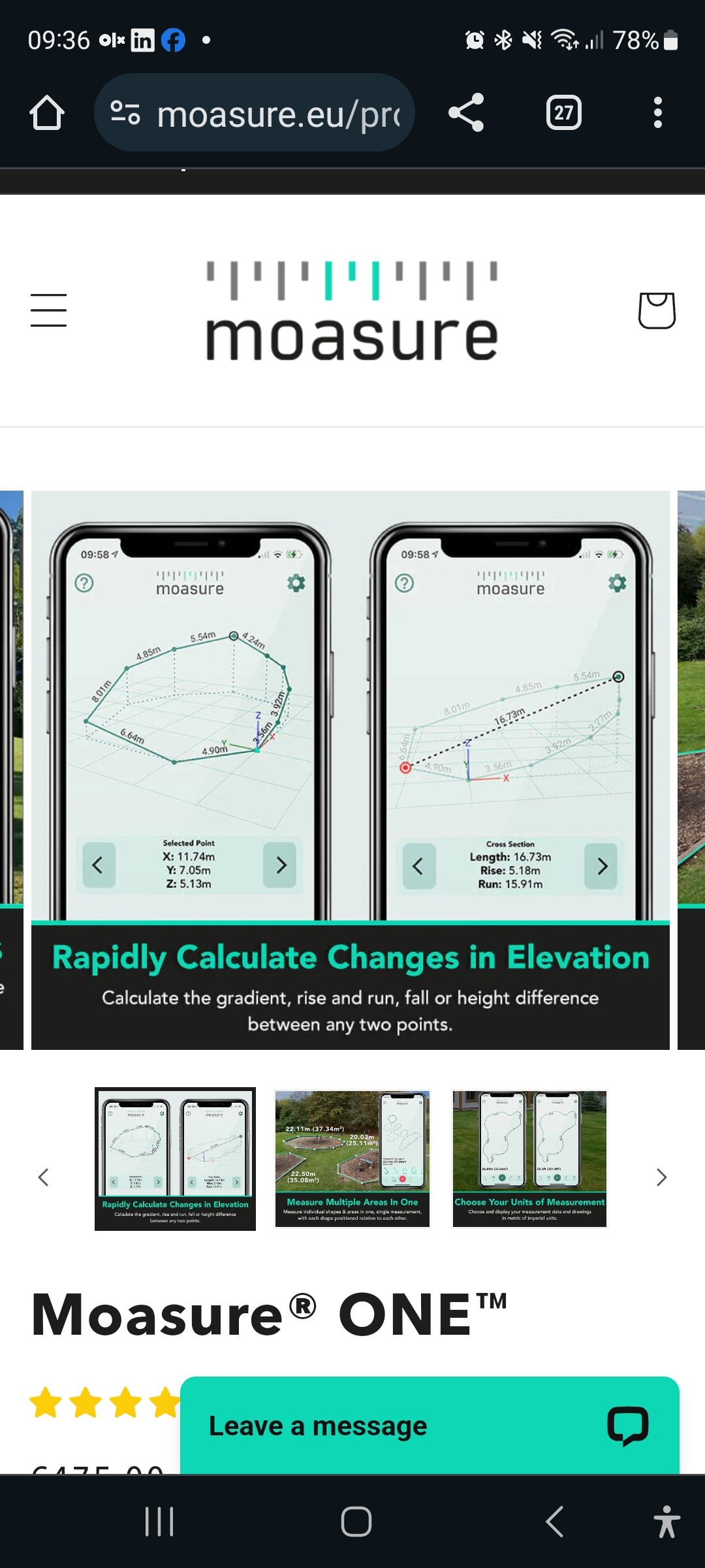
 Hi, have You heard about Moasure measuring tool? I'm wondering about it's precision and would like to here users opinion. It looks very useful considering that every measurement area ends with cad file data and includes area shape and elevation. They also advertise it as Vectorworks compatible (probably od DWG file import) Also its price is quite reasonable. Any comments?

-
Hi all, I have been doing some 1:5 details and I've found myself using loads of screws from the toolsets (architecture) but I cannot for the life of me find Nails, so I'm guessing that the industry left the nails in the bin and stopped using them or just Vectorworks doesn't like nails?? I use the screw tool to simulate the nail but never gives the proper look of a nail I know you can make your own symbol but is it that hard to give also the option to make the Nail part of those same tools as the screws??
-
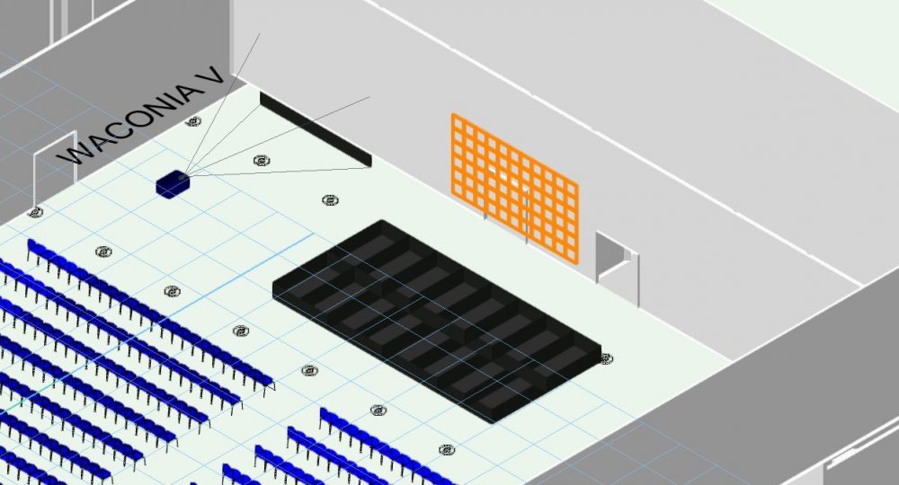
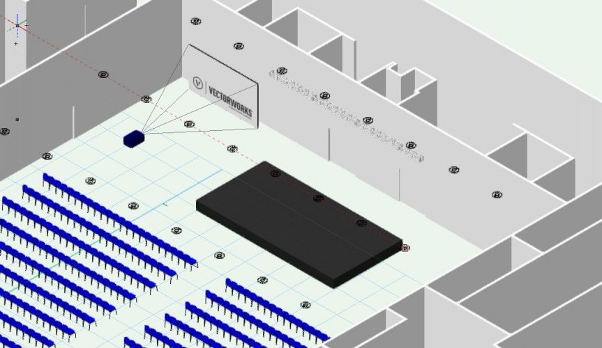
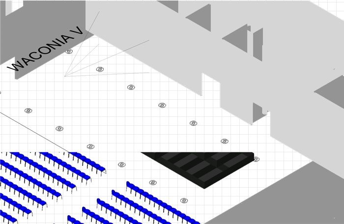
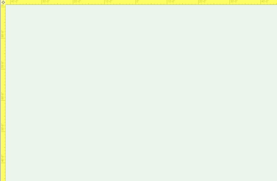
LED Screen tool is currently completely unusable for me. Whenever I insert an LED Screen object, I get very strange behavior in 3D views. Objects disappear or appear incorrectly. Which objects appear at all, and how they appear changes depending on zoom and viewing angle in flyover. Bug carries over into viewports. Additionally, ONLY after inserting an LED Screen, every time I enter flyover WITHOUT an object selected I get a blank canvas with yellow highlighted rulers. Attached are screenshots of a basic event layout in isometric view before inserting the LED screen, after inserting it, showing the screen selected but invisible, hollow stage(?) missing doors, 3D text showing through wall... just a mess. And a viewport of the same that's even more fun. For now I will use projection screen objects to fake it, but this is extremely frustrating. I was away from VW for most of the pandemic because, well, not a lot of live events to draw. This issue is new for me since updating VW and returning to this side of the work a month or two ago, but is consistent. The first time it occurred, I thought I just had a corrupted file, tried copy-paste into a new doc, no luck. Re-drew the whole event, same issue. I'm on a brand new installation as I've moved to a network server license, and it has persisted exactly the same way. Any help appreciated. Am I alone in this? Housing First 2021 Mystic v2.vwx
-
Something happened with graphic attributes in space tool. It seems impossible to have a label 100% opaque and 2D boundary in less than 100% opacity. This functionality was working in VW2018 but 2019 and 2020 has rearranged info and settings boxes and it is no longer possible. Its kind of indispensable when dong planing and color coding different uses etc.
-

Add Grid Tool to Spotlight Version
Tom M. posted a question in Wishlist - Feature and Content Requests
Hi, I'm a German Spotlight User and found in the Architecture Version the Grid Tool (in German "Raster Werkzeug"). It's pretty useful for a lot of Situation like big Festival Sheets or Axes in Venues etc. Could you please add this tool to the Spotlight Version as well. Thanks in advance -

Wall Tool Inside Outside Left Right Marker
Asemblance posted a question in Wishlist - Feature and Content Requests
Hi All, It would be useful if it was much clearer which side of a wall is inside/outside/left/right. Whenever replacing a wall with a new wall style for instance, I've been adopting the trial an error approach. I know the wall when selected shows a tiny arrow on one end, but often this is obscured or out of view. Also (more importantly), this is not displayed if you have more than one piece of wall selected. So the typical workflow of selecting a bunch of walls to update/replace, guess a side to align, get it wrong, undo, redo, select opposite side align. Whilst I'm on it, a marker showing 'inside' and 'outside' of window objects when selected would also be handy. -
While browsing YouTube I've come across this video from the Belgium distributor of Vectorworks and shows a very, VERY capable Window Tool, looks far superior to the one we already have in Vectorworks and is not a separate plugin , so why this is not part of the regular Vectorworks version? Window tool
-
Hello, I am simply trying to scale down some objects in a very rough way so that it can fit on a page and be printed. The only way I know how is to go into the modify menu and scaling it that way. Its a very tedious method of doing this as I am not sure how much I need to scale, and therefore constanly adjusting. Is there a way to have like a sort of scale box where I can simply drag the scale larger and smaller? Essentially I am trying to visually see the scale adjustment with a single command so that I dont need to guesstimate constantly, while re adjusting. Kind of like the scale tool in Autocad and Sketchup Any help would be really appreciated!
-
I had a quick search but I couldn't find anything. Is there a function in Vectorworks Spotlight 2017 that allows me to insert a lighting symbol at different lengths? So the length of the symbol is variable? For instance, when I draw LED tape the length is never a set amount. It is normally set to the size of scenery or buildings. Which means there are sometimes over 10 different lengths the symbol can be. Which makes reports and instrument summaries a nightmare. I think it will be really useful if there was a tool in which you could choose the type of LED Tape (For example RGBW @ 8w per meter). And be able to draw the tape live on the plan. Sort of like how the truss tool works but more of a click and drop like system (So you can create curved tape). It would then be useful for this to automatically be a singular lighting symbol and add information to the `Light Info" records. For example standard lantern information such as Unit Numbers, Circuit Numbers, Purposes, Positions. And additionally new information such as automatic Tape lengths, splits, and final wattages calculated from the watts per meter given and the variable length. I think when it comes to the instrument summary it would be useful if there was just one symbol that showed a section of the length. Named for example RGBW LED Tape. At the moment this is possible but the build list is flooded with 10 different lighting symbols for LED Tape. I know you can choose to hide/show symbols in the build list but symbol management would be so much organised. Let me know if this does or does not exist. Hopefully, I haven't been too oblivious. Many Thanks, Ryan Lawrence
-
 Hi there, I wish, there was a way to stamp an object's database information to it. I know that some local versions like the German (called 'Multistempel' or multistamp) already have this feature, but it doesn't always work properly. So I was hoping that there will be a generic version of this tool. On top it would be nice to gain access to the internal databases also. For example: I stamp the x and y coordinates value of an rectangle right onto that rectangle with the ability to change the coordinates by clicking right into the text in the drawing and editing it. What do you think? Kind regards VvierA
 -

Fence Railing Tool and Workgroup Folders
ericjhberg posted a question in Wishlist - Feature and Content Requests
We have been playing around with the new fence/railing tool and like that you can save as symbols to a custom location. It just so happens that custom location is only the USER folder. This is fine for personal storage, but in a large office, we need the ability to link this tool to a WORKGROUP folder as well. Of course, with the resource manager, custom symbols can be easily located in either location, but in the tool itself, it seems that the custom profiles are only loaded from a USER folder and not from a mirrored location in a WORKGROUP folder.