Matt Panzer
-
Posts
3,336 -
Joined
-
Last visited
Content Type
Profiles
Forums
Events
Articles
Marionette
Store
Everything posted by Matt Panzer
-
Hi @Christian Fekete, Can you send me the previous Vectorworks version file before it was opened in 2021?
-

Can't edit length of interior elevation section-elevation line
Matt Panzer replied to sara.t's question in Troubleshooting
@sara.t, Try the following in the file you're having the issue in: Select the Section-Elevation Marker tool in the Dim/Notes tool set. Click on the Tool Preferences button in the mode bar. The Section-Elevation Line Object Properties dialog will open. Change the Configuration popup to "Section". Note: If the popup is disabled, click on the Style popup at the top of the dialog and select "Convert to Unstyled". That will enable the Configuration popup. Those steps should set the document defaults for newly placed Section-Elevation Lines when creating Interior Elevation Markers. -
I don't see the issue in your file. You may also want to try switching to a standard workspace to see if that fixes anything. If it does, Pat's suggestion of removing and adding them back in the custom workspace may fix it. If that doesn't work, I would suspect the user folder. The easiest way to test that is to try the following: Quit VW Rename your VW user folder (eg: from "2021" to "2021-BAK") Run VW and see if the problem is resolved If the problem is resolved, there's an issue with something in the user folder. If the problem is still there and you want your old user folder back, quit VW, delete the newer "2021" folder and rename "2021-BAK" back to "2021".
-
I'm not seeing this issue. Is it by chance a styled cabinet with the "Hide Style Parameters" option selected int he Object Info palette? If not, can you attach a file with the cabinet in it?
-
Section Viewport : Merging objects with same fill. Bug ?
Matt Panzer replied to Stéphane's question in Troubleshooting
Thank you for the test file. This looks like a bug and I just submitted a bug report on it (VB-174813). Have you tried the "Add Profile Line" option? While this does not correct everything, it helps quite a bit in this case. -
Section Viewport : Merging objects with same fill. Bug ?
Matt Panzer replied to Stéphane's question in Troubleshooting
Can you attach (or send me privately) a file showing the issue? -
Door hardware appearing twice in hidden line
Matt Panzer replied to michaelk's question in Troubleshooting
Yes. This is a known bug and should be addressed in the next service pack. The problem seems to have to do with using symbols in door and window objects (eg: hardware, custom leaves, custom shutters). -
Disappearing Viewports -
Matt Panzer replied to hollister design Studio's question in Troubleshooting
Does it correct the problem if you change the Navigation Graphics to something other than "Best Performance" (in the Display pane of the Vectorworks Preferences)? -
@Tom W., Very cool! It's great to see the different uses for this!
-
Yeah. But, as I mentioned to Tom, this is not the intended purpose of 3D Wall Holes in symbols. I don't believe you want to show slate shingles on a roof like this. I tried it on a wall and it's far too much detail. Great! Please let us know how it works for you if you use it!
-
Thanks! I originally tried making separate shake shingles but, as I predicted, the performance was not good. So these became boards. But yeah, that little bit of space behind the boards worked out nice. That must've come from Vectorworks 2021's "Wood 2x Framing Insulated - 16in O.C. MT" material resource when I exported back. Absolutely! Right. But please note that this really is a clever workaround for doing these things. I would limit the use of this to simpler more basic things.
-
Yes, of course. And they should not be perfectly round either. Since I've already uploaded the file, I'll let you add them. I don't want to keep all the fun to myself! 😉
-
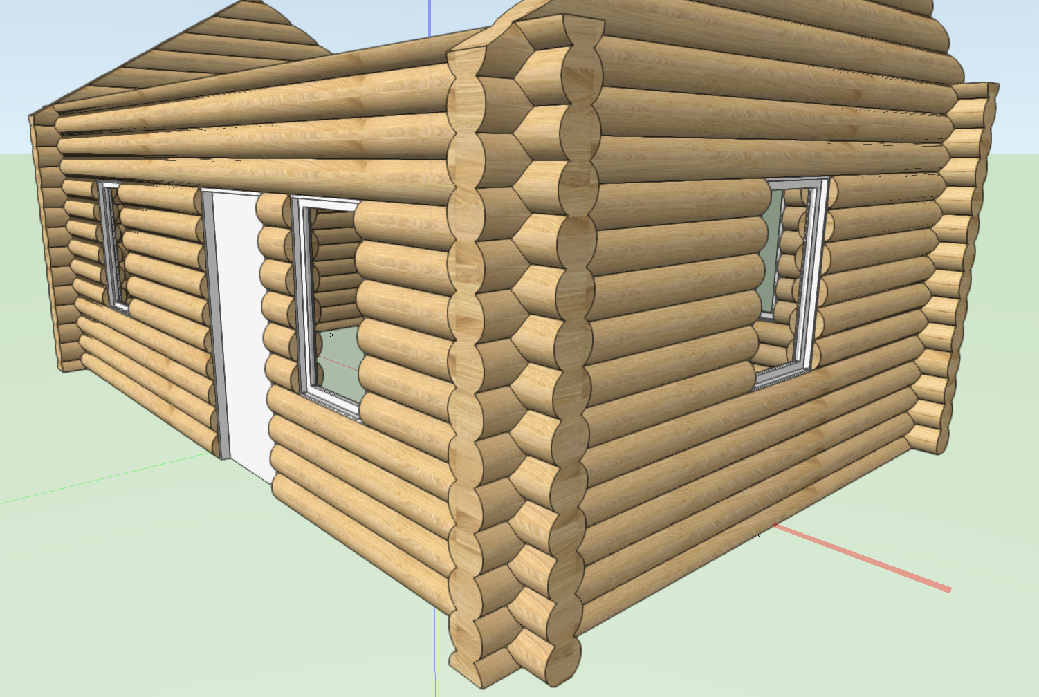
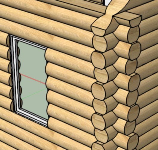
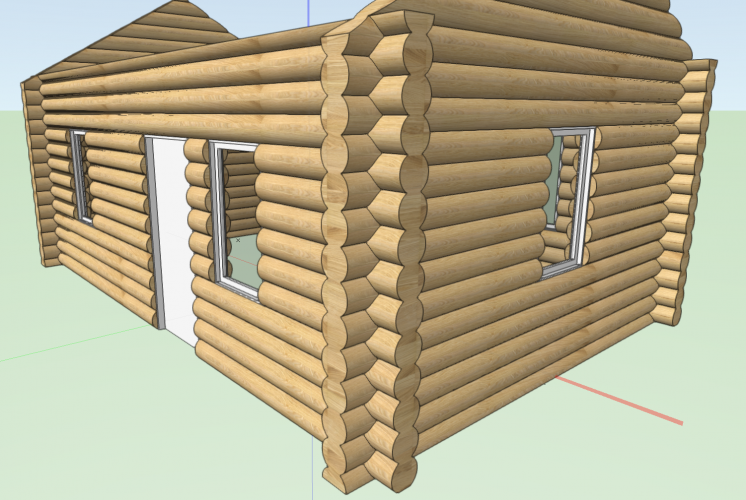
Here's a newer version of the file with the log end cutter symbols. These symbols are inserted at the very end of each wall so they do move along with them. However, if you drag the endpoint of a wall to make it longer, it will not move along with the end. Log Cabin Wall Log Cutter Symbol v2020.vwx
-
Nice @Tom W.! BTW: The wall ends all being flush was bothering me. So I create another symbol to place at the end of each wall to cut pieces out at varying offsets.
-
I'm not sure how far and complex you can go either and would certainly be cautious. The hole can, however, cut out anything from any part of the wall's 3D geometry. It essentially is subtracted from the wall. In theory, you could cut out spaces between studs and sculpt the siding component with hole geometry but I think the performance will quickly slow to a crawl. I'm especially thinking of cutting out geometry for things like shake siding. I would limit the use of this for fairly simple things.
-
Certainly a possibility! I’m thinking wall joins could get hairy though. 😉 True, But still a possibility! Well now you’re putting the cart before the horse! 😛
-
Thanks @zoomer ! I should've mentioned that you probably want another version of the log cutter symbol with the extrude offset 4" down to use in every other wall. That will get the logs interlocking each other. You could also use the same symbol but will need to change its Z height in every other wall: You can do some pretty cool things with wall holes in symbols. They're great for creating reveals in walls as well. The nice thing about them is that the hole geometry will cut the walls all the way to the ends (even when walls L-join).
-
I'm chiming in a little late on this, but I have a pretty cool solution you might want to try. 🙂 The idea is to create a symbol with 2D and 3D loci (to allow selection of the instances) and wall hole hole geometry that cuts out the log shapes from the wall. Log Cabin Wall Log Cutter Symbol.mp4 Log Cabin Wall Log Cutter Symbol v2020.vwx
- 56 replies
-
- 30
-

-

-
Thanks for the file. I suspected this was a known issue (and it is - VB-174200) but wanted to make sure. I'll note this thread in the existing bug report. Thanks!
-
Can you upload a file that shows the problem (maybe make a copy of the file and delete everything but a wall with the windows and the sheet layer viewport)? Or you can send me the file privately.
-
Section cut casting an unwanted shadow
Matt Panzer replied to Stéphane's question in Troubleshooting
Thanks for clarifying this, Dave. So there are more options other than OpenGL. Stephane, You may want to try a non-artistic Renderworks mode and apply Image Effects to the viewport. This might get the rendering a little more "stylized" than straight Renderworks. Just a thought. -
Section cut casting an unwanted shadow
Matt Panzer replied to Stéphane's question in Troubleshooting
Thank you for the file. I took a look and see the issue. I investigated this and found it is a known bug that affects a Renderworks modes. OpenGL, however, does provide correct shadows (make sure to select Use Shadows on the OpenGL render settings of the viewport). If you can get by using Open GL, that would be a possible workaround for now.- 11 replies
-
- 1
-

-
- section vp
- sectioncut
- (and 1 more)
-
Staircase 2D graphics issues in Horizontal Section Viewport - VW 2020
Matt Panzer replied to drelARCH's question in Troubleshooting
I was assuming @drelARCH was talking about the new 'Top Graphic' feature for the stair in VW 2021. That is the feature I'm describing. -
Section cut casting an unwanted shadow
Matt Panzer replied to Stéphane's question in Troubleshooting
Can you upload a small file showing the problem? Maybe make a copy of the file, delete everything out but the walls and slabs involved (and the section viewport), and purge all unused stuff? If you'd rather, you can send the file as it is to me privately. -
Staircase 2D graphics issues in Horizontal Section Viewport - VW 2020
Matt Panzer replied to drelARCH's question in Troubleshooting
You're welcome for the help! Are you talking about an unrelated issue? This is essentially what we've done. The stair now places the same "upper floor" plan graphics in the main (lower floor) stair object's Top 2D component. This means you can choose not to display the upper floor graphic (proxy object) if only using horizontal sections. Also, the Top 2D component's location (Z height) will default to a location that is always above the upper floor of the stair. This insures the Top component always displays above the upper floor slab. Of course, if you want the location to be below the slab, you can edit the Top 2D component location and move it down to where you want. The main lingering issue (related to 2D components) is the one of showing the upper part of the stair (eg: railing extensions) above the upper slab and the lower part of the stair below the upper slab. We are looking at better ways to handle this in the future. I'm glad you feel that way and I look forward to your review!